
Development of a Lizard-Inspired Robot for Mars Surface Exploration

Abstract
:1. Introduction
2. Biomimetic Structure Design
2.1. Biological Characteristics
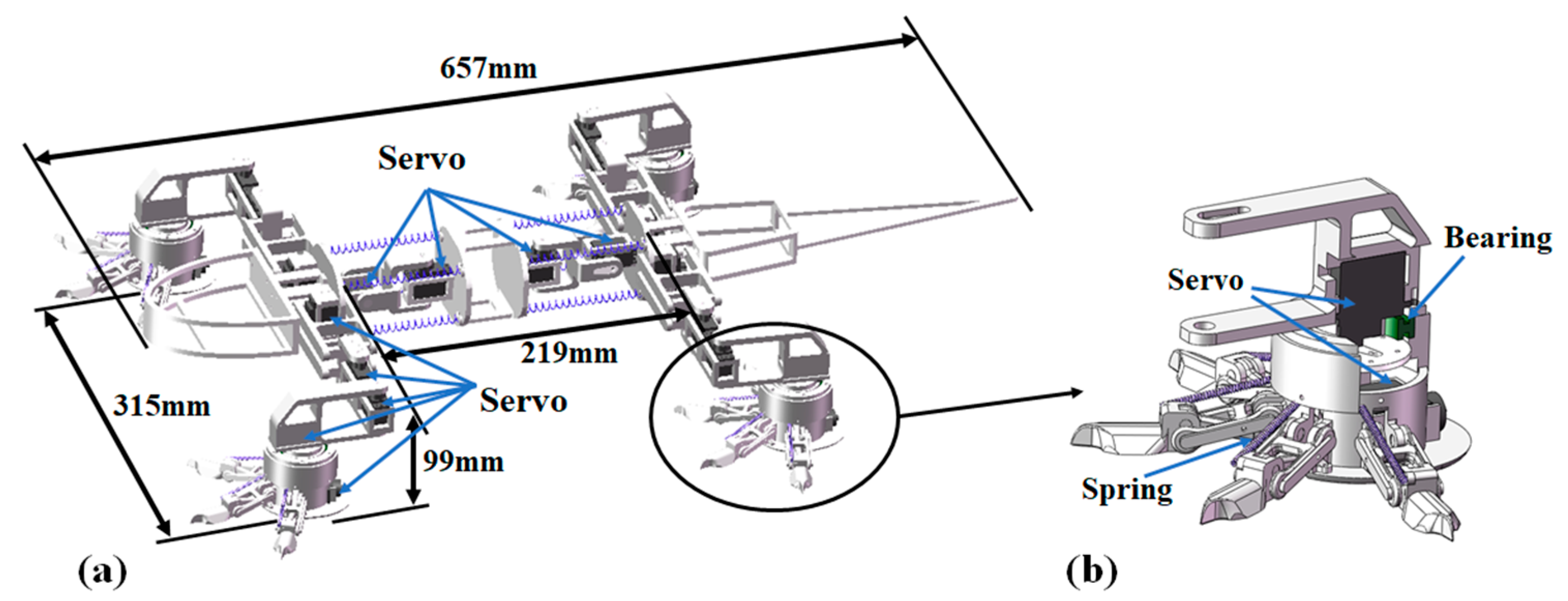
2.2. Biomimetic Structure
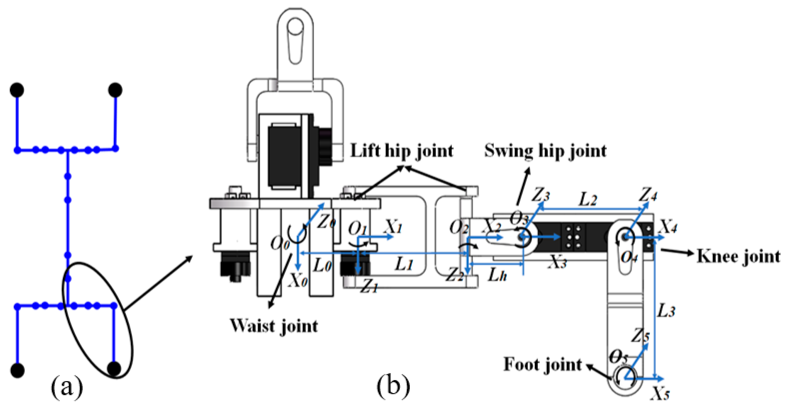
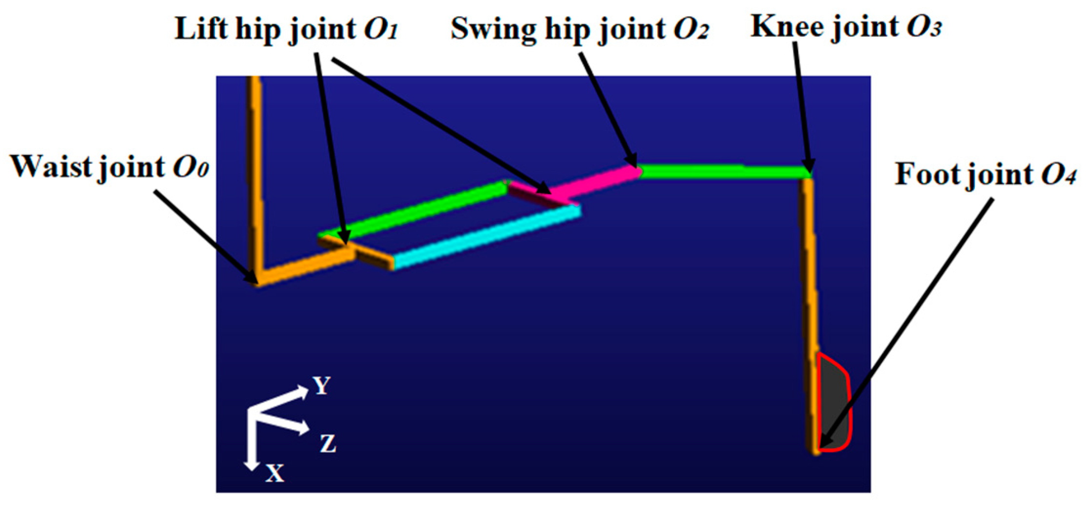
3. Kinematics Modelling
3.1. Leg Motion Determination
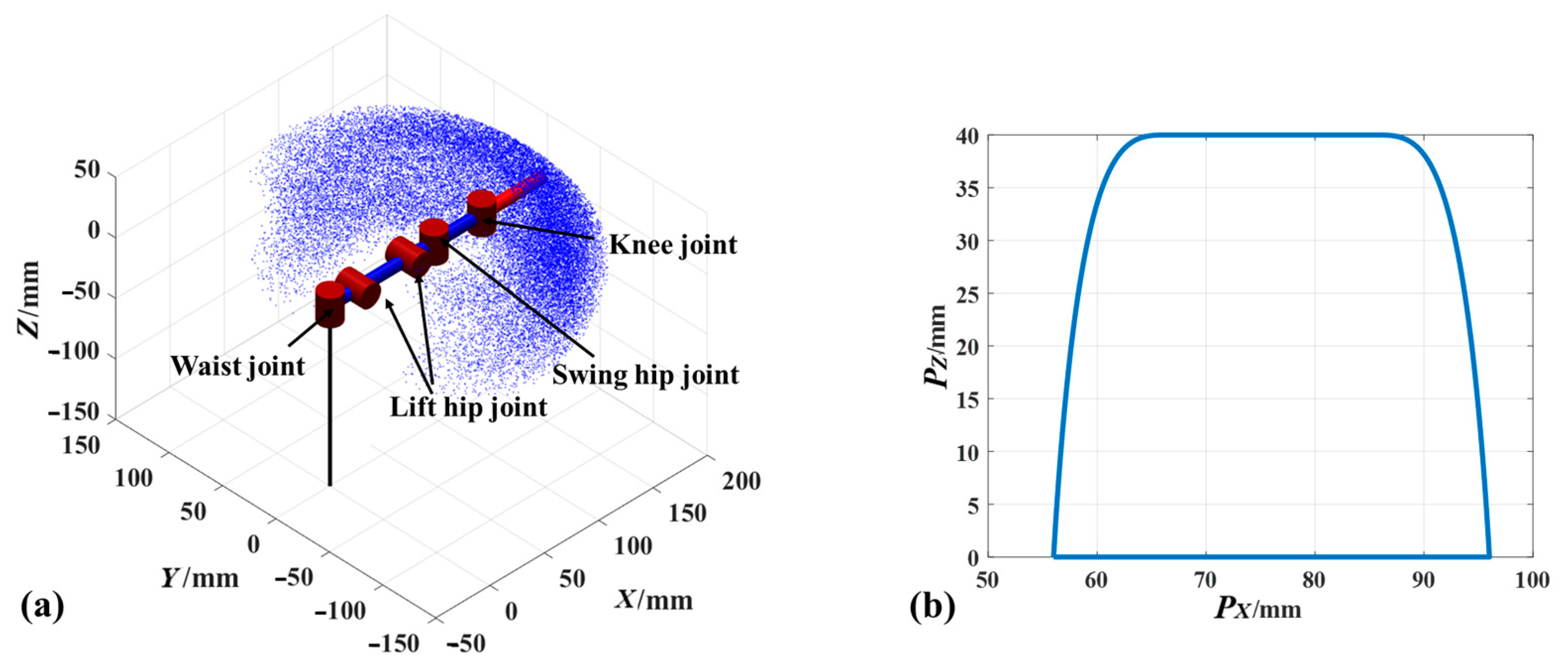
3.2. Work Space Estimation
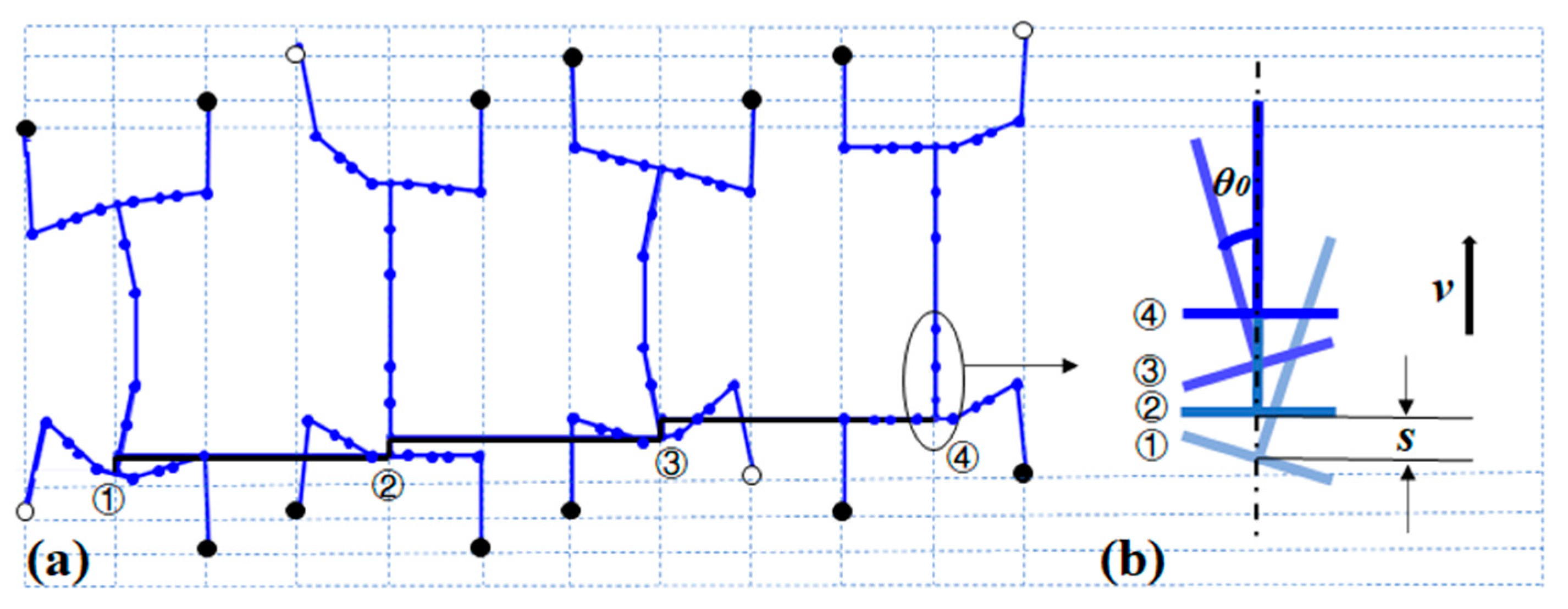
3.3. Gait Planning
4. Verification by Simulation
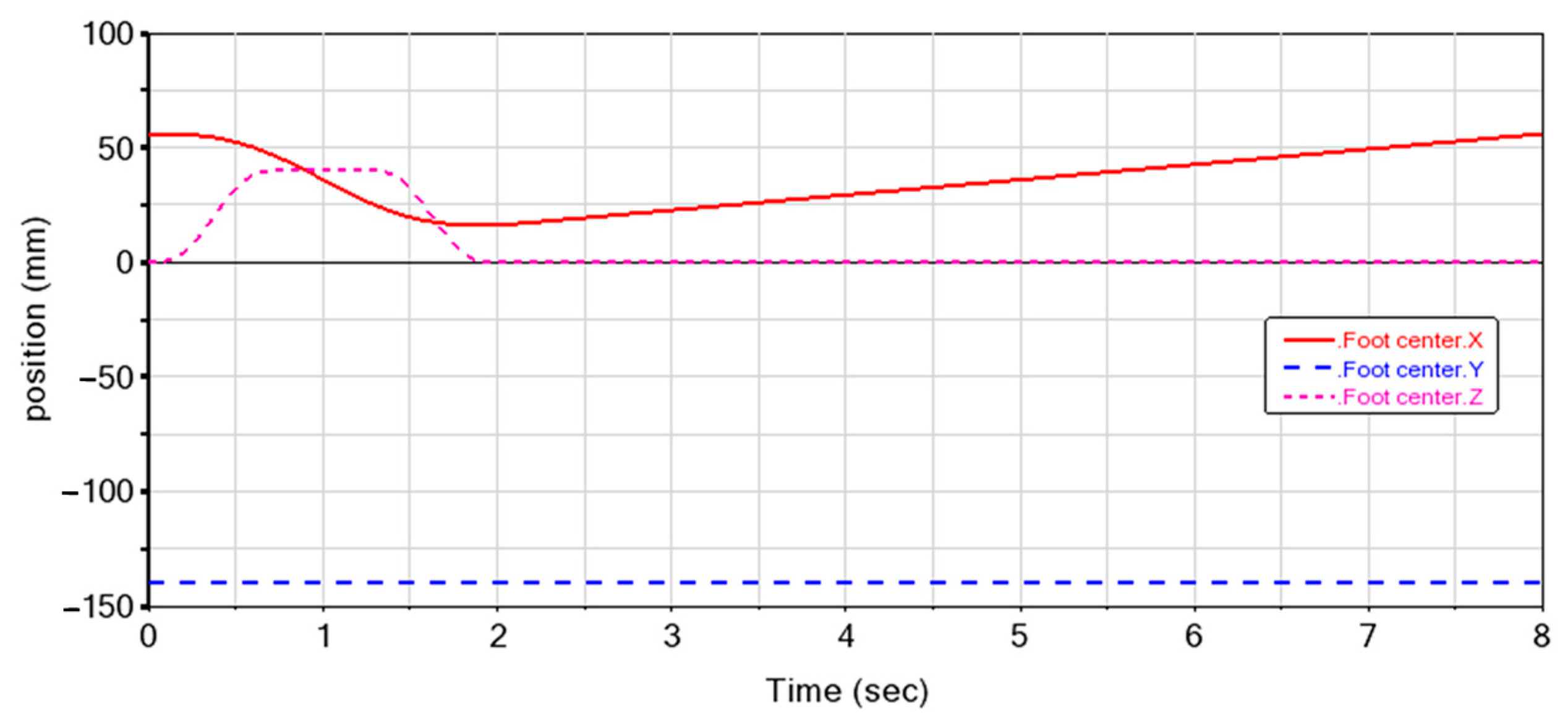
4.1. Leg Motion
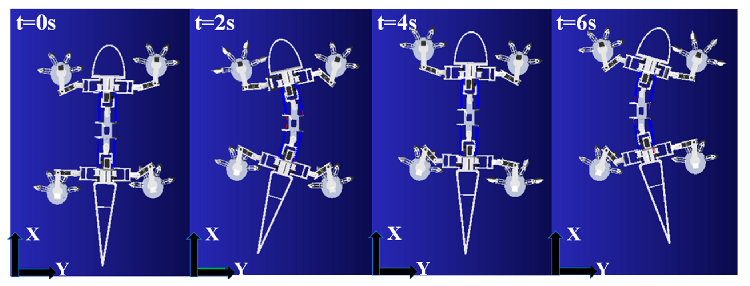
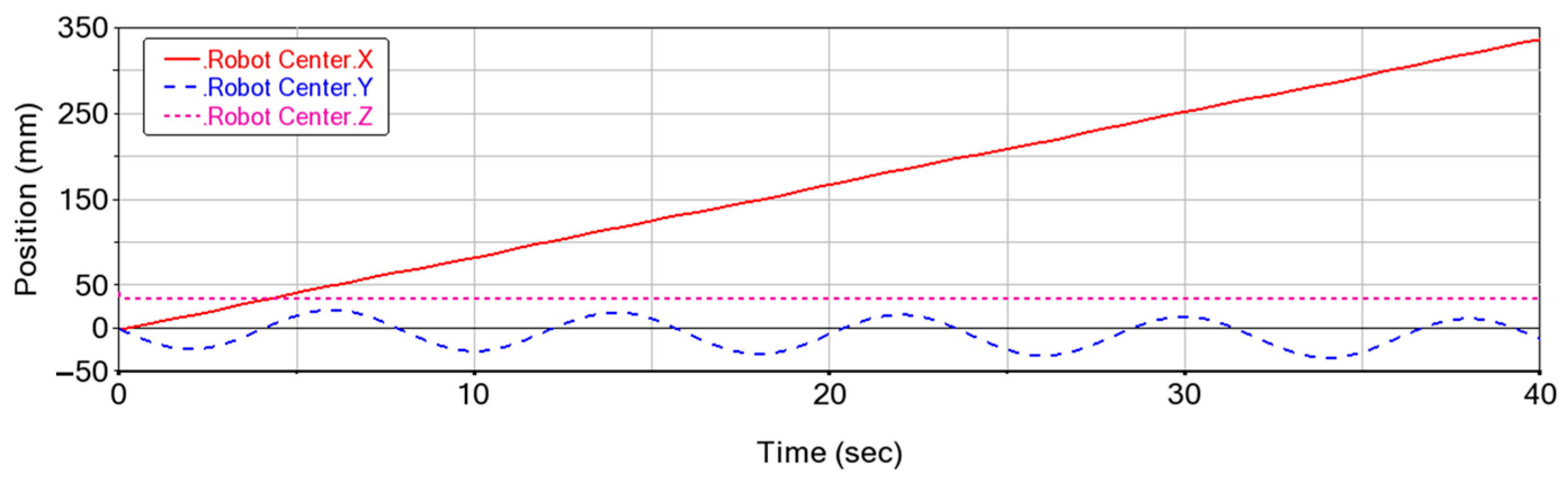
4.2. Gait Simulation
4.3. Grasping Simulation
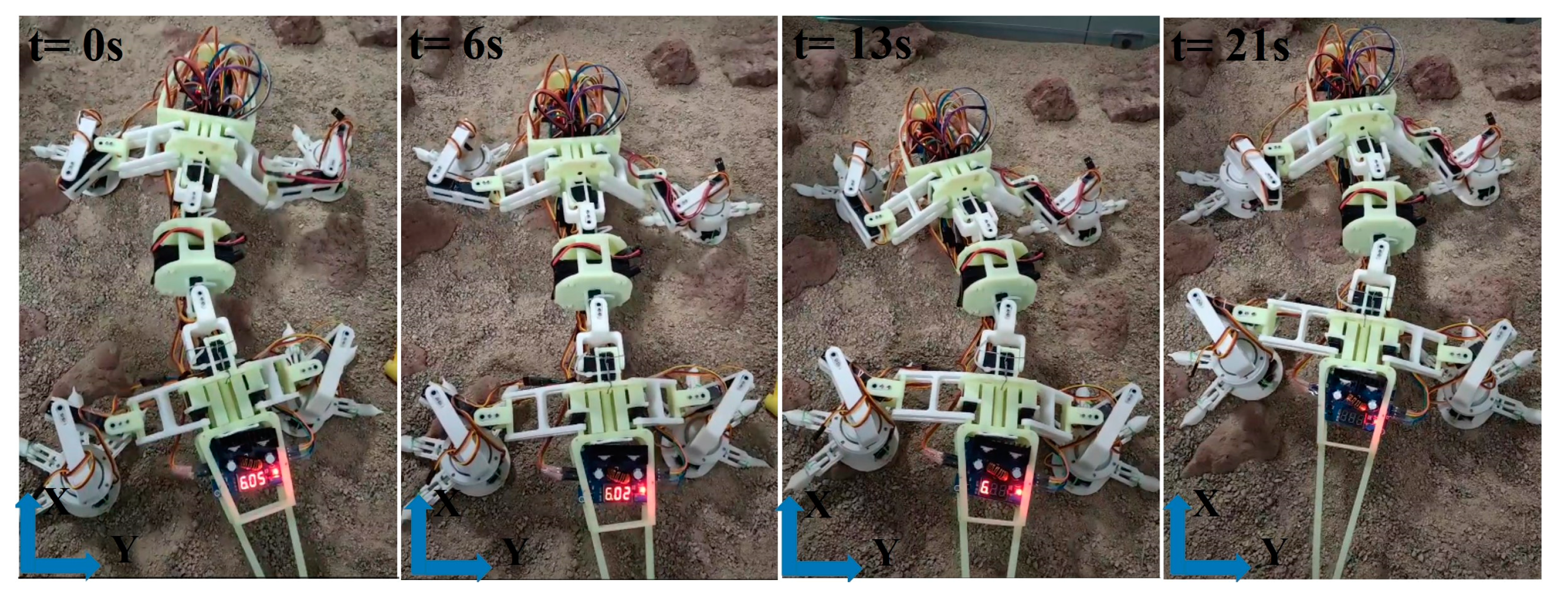
5. Experimental Tests
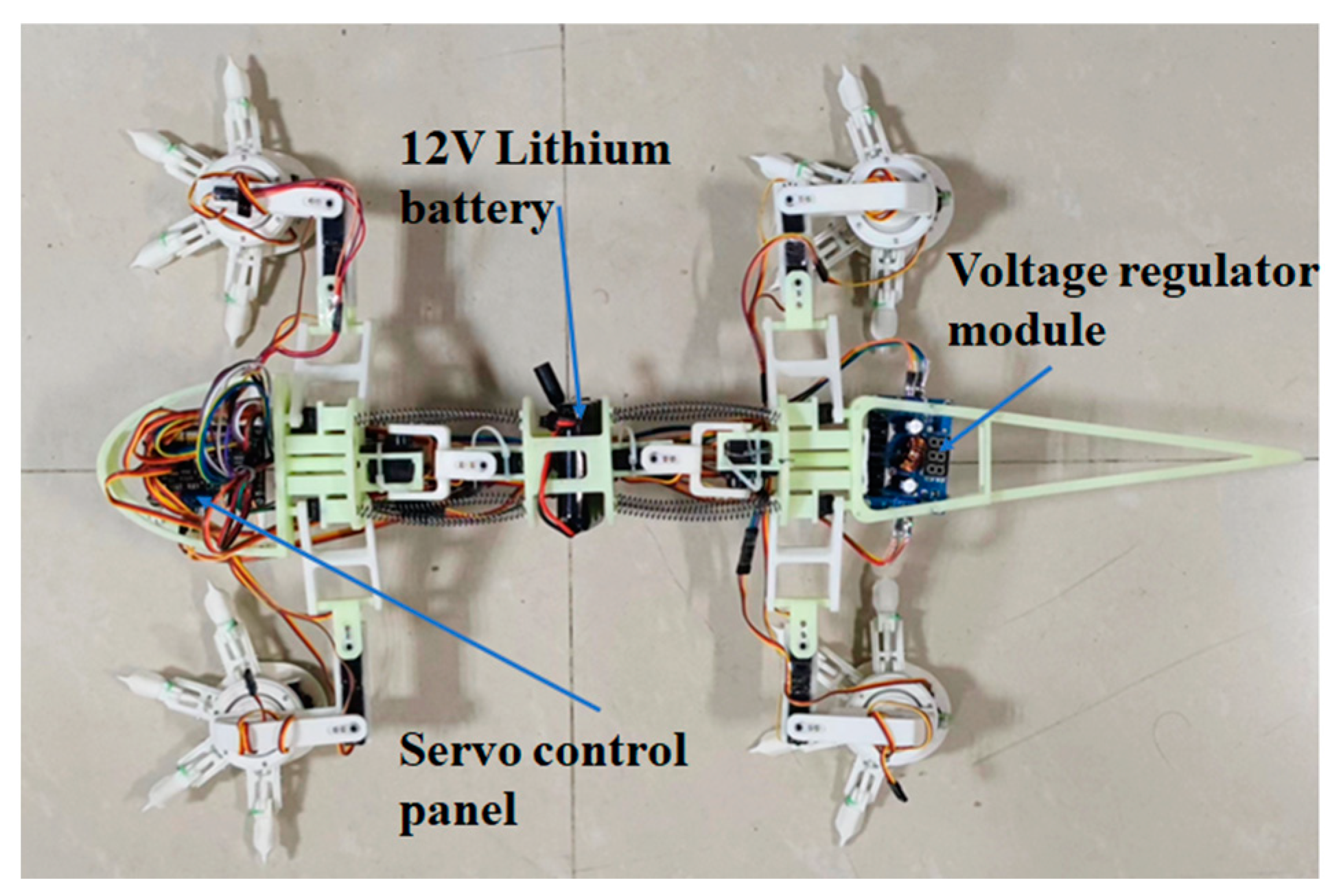
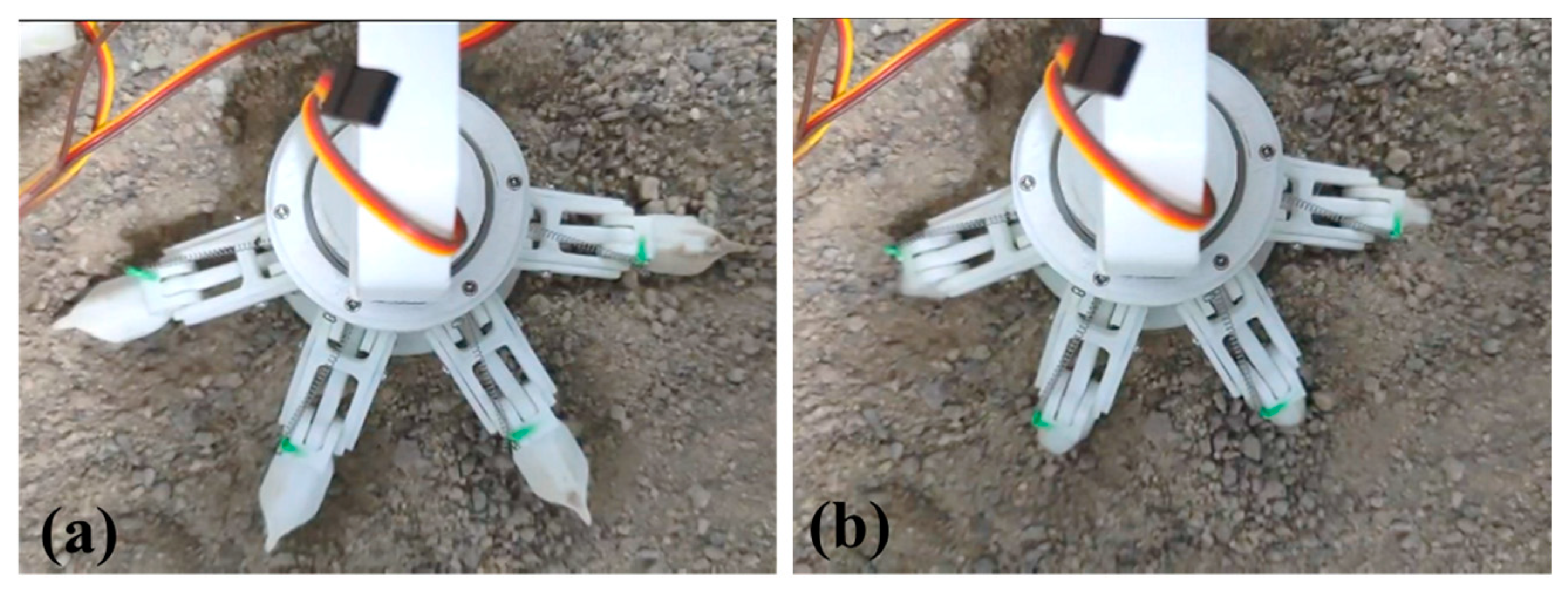
5.1. Fabrication
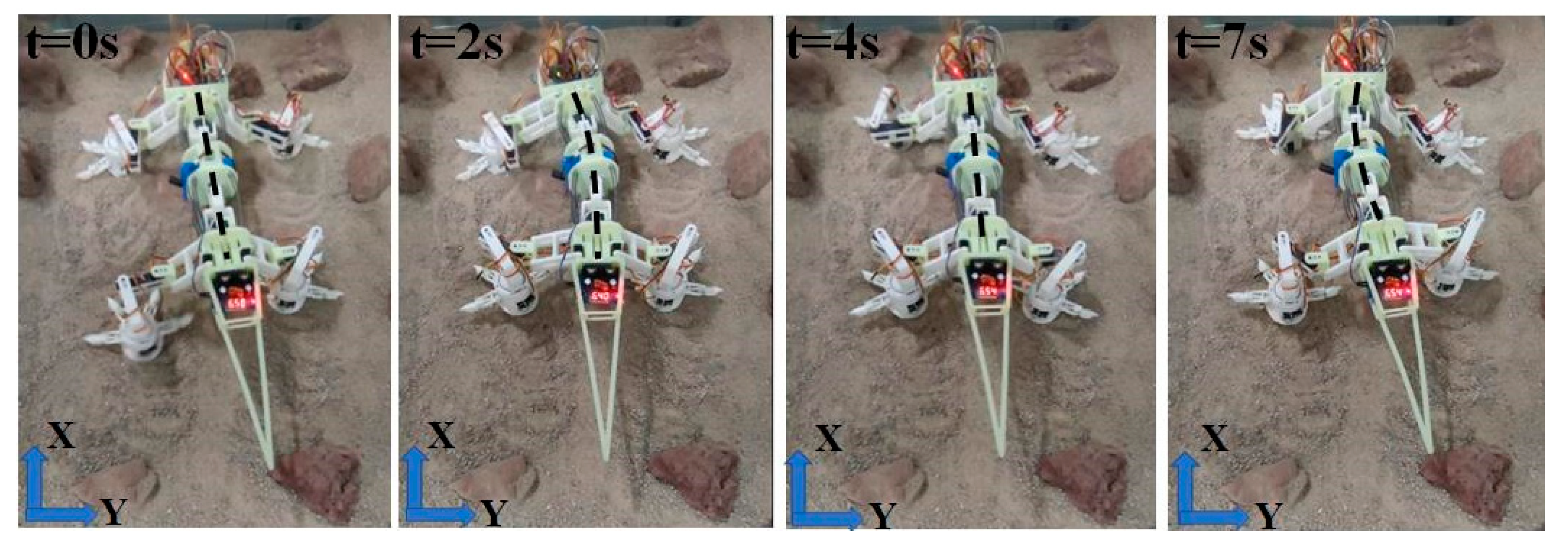
5.2. Mobility Test
6. Discussion
7. Conclusions
Supplementary Materials
Author Contributions
Funding
Institutional Review Board Statement
Data Availability Statement
Conflicts of Interest
References
- Malaya Kumar Biswal, M.; Ayyappan, S.; Thomas, A.; Ramesh Kumar, V.; Basanta Das, N. A Baseline Strategy for Human Mars Exploration. In Proceedings of the Accelerating Space Commerce, Exploration, and New Discovery Conference, Las Vegas, NV, USA, 15–17 November 2021. [Google Scholar]
- Salgado-Rodriguez, M.; Garcia-Luis, U.; Gomez-San-Juan, A.; Ulloa-Sande, C.; Navarro-Medina, F. Conceptual Design and Research on the Thermal Performance of a Martian Human Base. Acta Astronaut. 2022, 200, 524–538. [Google Scholar] [CrossRef]
- Oudart, N.; Ciarletti, V.; Le Gall, A.; Hervé, Y.; Brighi, E. Retrieval of the Ground Dielectric Permittivity by Planetary GPR Accommodated on a Rover: Application to the Estimation of the Reflectors’ Depth by the WISDOM/ExoMars Radar. Planet. Space Sci. 2022, 224, 105606. [Google Scholar] [CrossRef]
- Maki, J.N.; Gruel, D.; McKinney, C.; Ravine, M.A.; Morales, M.; Lee, D.; Willson, R.; Copley-Woods, D.; Valvo, M.; Goodsall, T.; et al. The Mars 2020 Engineering Cameras and Microphone on the Perseverance Rover: A Next-Generation Imaging System for Mars Exploration. Space Sci. Rev. 2020, 216, 137. [Google Scholar] [CrossRef]
- Li, C.; Zheng, Y.; Wang, X.; Zhang, J.; Wang, Y.; Chen, L.; Zhang, L.; Zhao, P.; Liu, Y.; Lv, W.; et al. Layered Subsurface in Utopia Basin of Mars Revealed by Zhurong Rover Radar. Nature 2022, 610, 308–312. [Google Scholar] [CrossRef] [PubMed]
- Almehisni, R.; Garg, P.; Wali, M. Thermal Management System Design and Analysis of Rashid Rover—Emirates Lunar Mission. In Proceedings of the International Astronautical Congress(IAC), Dubai, United Arab Emirates, 25–29 October 2021. [Google Scholar]
- Ceylan, S.; Clinton, J.F.; Giardini, D.; Stähler, S.C.; Horleston, A.; Kawamura, T.; Böse, M.; Charalambous, C.; Dahmen, N.L.; van Driel, M.; et al. The Marsquake Catalogue from InSight, Sols 0–1011. Phys. Earth Planet. Inter. 2022, 333, 106943. [Google Scholar] [CrossRef]
- Zhang, X.; Zhang, G.; Xie, H.; Gao, M.; Wen, Y. A Review of Sampling Exploration and Devices for Extraterrestrial Celestial Bodies. Space Sci. Rev. 2022, 218, 59. [Google Scholar] [CrossRef]
- Medina, F.J.; Manzano, A.; Villacampa, A.; Ciska, M.; Herranz, R. Understanding Reduced Gravity Effects on Early Plant Development Before Attempting Life-Support Farming in the Moon and Mars. Front. Astron. Space Sci. 2021, 8, 1–7. [Google Scholar] [CrossRef]
- Arvidson, R.E.; Bell, J.F.; Bellutta, P.; Cabrol, N.A.; Catalano, J.G.; Cohen, J.; Crumpler, L.S.; Des Marais, D.J.; Estlin, T.A.; Farrand, W.H.; et al. Spirit Mars Rover Mission: Overview and Selected Results from the Northern Home Plate Winter Haven to the Side of Scamander Crater. J. Geophys. Res. Planets 2010, 115, 1–19. [Google Scholar] [CrossRef] [Green Version]
- Yuan, B.; Wang, C.; Zou, M.; Liu, Y.; Lin, Y.; Jia, Y.; Chen, B.; Jin, J. Experimental Study on the Durability of China’s Mars Rover’s Mobility System. J. Aerosp. Eng. 2021, 34, 1–8. [Google Scholar] [CrossRef]
- Sunspiral, V.; Wheeler, D.W.; Chavez-Clemente, D.; Mittman, D. Development and Field Testing of the FootFall Planning System for the ATHLETE Robots. J. Field Robot. 2012, 29, 483–505. [Google Scholar] [CrossRef]
- Cordes, F.; Kirchner, F.; Babu, A. Design and Field Testing of a Rover with an Actively Articulated Suspension System in a Mars Analog Terrain. J. Field Robot. 2018, 35, 1149–1181. [Google Scholar] [CrossRef]
- Zhang, T.; Peng, S.; Jia, Y.; Tian, H.; Sun, J.; Yan, C. Slip Estimation for Mars Rover Zhurong Based on Data Drive. Appl. Sci. 2022, 12, 1676. [Google Scholar] [CrossRef]
- Arm, P.; Zenkl, R.; Barton, P.; Beglinger, L.; Dietsche, A.; Ferrazzini, L.; Hampp, E.; Hinder, J.; Huber, C.; Schaufelberger, D.; et al. SpaceBok: A Dynamic Legged Robot for Space Exploration. In Proceedings of the IEEE International Conference on Robotics and Automation 2019, Montreal, QC, Canada, 20–24 May 2019. [Google Scholar]
- Parness, A.; Abcouwer, N.; Fuller, C.; Wiltsie, N.; Nash, J.; Kennedy, B. LEMUR 3: A Limbed Climbing Robot for Extreme Terrain Mobility in Space. In Proceedings of the IEEE International Conference on Robotics and Automation (ICRA) 2017, Singapore, 29 May–3 June 2017. [Google Scholar]
- Nagaoka, K.; Minote, H.; Maruya, K.; Shirai, Y.; Yoshida, K.; Hakamada, T.; Sawada, H.; Kubota, T. Passive Spine Gripper for Free-Climbing Robot in Extreme Terrain. IEEE Robot. Autom. Lett. 2018, 3, 1765–1770. [Google Scholar] [CrossRef]
- Biswal, P.; Mohanty, P.K. Development of Quadruped Walking Robots: A Review. Ain Shams Eng. J. 2021, 12, 2017–2031. [Google Scholar] [CrossRef]
- Chen, G.; Qiao, L.; Wang, B.; Richter, L.; Ji, A. Bionic Design of Multi-Toe Quadruped Robot for Planetary Surface Exploration. Machines 2022, 10, 827. [Google Scholar] [CrossRef]
- Wang, W.; Ji, A.; Chen, G.; Ravi, S.; Shen, H.; Gorb, S.N.; Dai, Z. Kinematics of Gecko Climbing: The Lateral Undulation Pattern. Zoology 2020, 140, 125768. [Google Scholar] [CrossRef]
- Li, C.; Hsieh, S.T.; Goldman, D.I. Multi-Functional Foot Use during Running in the Zebra-Tailed Lizard (Callisaurus Draconoides). J. Exp. Biol. 2012, 215, 3293–3308. [Google Scholar] [CrossRef] [Green Version]
- Haomachai, W.; Shao, D.; Wang, W.; Ji, A.; Dai, Z.; Manoonpong, P. Lateral Undulation of the Bendable Body of a Gecko-Inspired Robot for Energy-Efficient Inclined Surface Climbing. IEEE Robot. Autom. Lett. 2021, 6, 7918–7925. [Google Scholar] [CrossRef]
- Uno, K.; Koizumi, Y.; Haji, K.; Kei, M.; Harms, S.; Ribeiro, W.F.R.; Nagaoka, K.; Yoshida, K. Non-Periodic Gait Planning Based on Salient Region Detection for a Planetary Cave Exploration Robot. In Proceedings of the i-SAIRAS, Virtual Conference, 19–23 October 2020. [Google Scholar]
- Chen, M.; Li, Q.; Wang, S.; Zhang, K.; Chen, H.; Zhang, Y. Single-Leg Structural Design and Foot Trajectory Planning for a Novel Bioinspired Quadruped Robot. Complexity 2021, 2021, 6627043. [Google Scholar] [CrossRef]
- Zhang, D.; Fang, T.; Yang, Y.; Fang, T.; Guo, Z. Static Gait Planning of a Quadruped Robot with Four-Bar Shock Absorbing Mechanism. In Proceedings of the 7th International Conference on Mechatronics and Robotics Engineering (ICMRE), Budapest, Hungary, 5–9 February 2021. [Google Scholar]
- Zhang, C.; An, H.; Wei, Q.; Ma, H. Foot Trajectory Planning Method with Adjustable Parameters for Complex Environment. In Proceedings of the IEEE International Conference on Robotics and Biomimetics, Dali, China, 27–31 December 2019. [Google Scholar]
- Yuan, S.; Zhou, Y.; Luo, C. Crawling Gait Planning Based on Foot Trajectory Optimization for Quadruped Robot. In Proceedings of the 2019 IEEE International Conference on Mechatronics and Automation, Tianjin, China, 4–7 August 2019. [Google Scholar]
- Corke, P.I. Robotics Toolbox. 2002. Available online: Http://www.Petercorke.Com/Robotics%20Toolbox.Html (accessed on 10 December 2022).
- MSC Software “ADAMS 2013.2 Solver User Manual”. 2013. Available online: https://www.mscsoftware.com/page/adams (accessed on 10 December 2022).
- Fang, S.; Xie, C.; Wu, X.; Wang, X. Design of a Quadruped Wall-Climbing Robot (WCR) with a Three-Row Opposed Gripping Mechanism. In Proceedings of the 2021 IEEE International Conference on Real-Time Computing and Robotics (RCAR), Xining, China, 15–19 July 2021. [Google Scholar]
- Cannon, K.M.; Britt, D.T.; Smith, T.M.; Fritsche, R.F.; Batcheldor, D. Mars Global Simulant MGS-1: A Rocknest-Based Open Standard for Basaltic Martian Regolith Simulants. Icarus 2019, 317, 470–478. [Google Scholar] [CrossRef]
- Yu, W.; Zeng, X.; Li, X.; Wei, G.; Fang, J. New Martian Dust Simulant JMDS-1 and Applications to Laboratory Thermal Conductivity Measurements. Earth Space Sci. 2022, 9, 1–15. [Google Scholar] [CrossRef]
- Golombek, M.P.; Trussell, A.; Williams, N.; Charalambous, C.; Abarca, H.; Warner, N.H.; Deahn, M.; Trautman, M.; Crocco, R.; Grant, J.A.; et al. Rock Size-Frequency Distributions at the InSight Landing Site, Mars. Earth Space Sci. 2021, 8, e2021EA001959. [Google Scholar] [CrossRef]
- Schultz, J.T.; Beck, H.K.; Haagensen, T.; Proost, T.; Clemente, C.J. Using a Biologically Mimicking Climbing Robot to Explore the Performance Landscape of Climbing in Lizards. Proc. Biol. Sci. 2021, 288, 20202576. [Google Scholar] [CrossRef] [PubMed]
- Ijspeert, A.J. Amphibious and Sprawling Locomotion: From Biology to Robotics and Back. Annu. Rev. Control Robot. Auton. Syst. 2020, 3, 173–193. [Google Scholar] [CrossRef]
- Karakasiliotis, K.; Thandiackal, R.; Melo, K.; Horvat, T.; Mahabadi, N.K.; Tsitkov, S.; Cabelguen, J.M.; Ijspeert, A.J. From cineradiography to biorobots: An approach for designing robots to emulate and study animal locomotion. J. R. Soc. Interface 2016, 13, 20151089. [Google Scholar] [CrossRef] [Green Version]
- Schott, D.; Mohajeri, J.; Jovanova, J.; Lommen, S.; de Kluijver, W. Design Framework for DEM-Supported Prototyping of Grabs Including Full-Scale Validation. J. Terramechanics 2021, 96, 29–43. [Google Scholar] [CrossRef]
- Alshehhi, R.; Gebhardt, C. Detection of Martian Dust Storms Using Mask Regional Convolutional Neural Networks. Prog. Earth Planet. Sci. 2022, 9, 1–16. [Google Scholar] [CrossRef]
- Zhu, X.; Wan, J.; Zhou, C.; Xu, W. A Composite Robust Reactive Control Strategy for Quadruped Robot under External Push Disturbance. Comput. Electr. Eng. 2021, 91, 107027. [Google Scholar] [CrossRef]
- Lopez-Arreguin, A.J.R.; Montenegro, S. Machine Learning in Planetary Rovers: A Survey of Learning versus Classical Estimation Methods in Terramechanics for in Situ Exploration. J. Terramechanics 2021, 97, 1–17. [Google Scholar] [CrossRef]
- Morgan, A.B.; Kumar, J.; Barklay, C.D.; Kramer, D.P. Non-Nuclear Based Thermoelectric + Battery System Concepts for Space Power Systems. In Proceedings of the 2020 IEEE Aerospace Conference, Big Sky, MT, USA, 21 August 2020. [Google Scholar]


| Link | Torsional Angle α | Link Length L | Joint Angle | Joint Distance |
|---|---|---|---|---|
| 1 | 90° | L0 | 0 | |
| 2 | 0° | L1 | 0 | |
| 3 | −90° | Lh | 0 | |
| 4 | 0° | L2 | 0 | |
| 5 | 0° | L3 | 0 |
| Categories | Parameters | Values |
|---|---|---|
| Materials | Steel density | 7801 Kg/m3 |
| Steel Young’s Modulus | 2.07 GPa | |
| Steeel poisson ratio | 0.29 | |
| Spring stiffness | 4.6 N·mm/° | |
| Concrete | 2000 Kg/m3 | |
| Contact | Stiffness | 4855 N/mm |
| Damping | 80 N s/mm | |
| Penetration depth | 0.1 mm | |
| Static coefficient | 0.7 | |
| Dynamic coefficient | 0.57 | |
| Static transition velocity | 0.1 mm/s | |
| Friction transition velocity | 10 mm/s |
Disclaimer/Publisher’s Note: The statements, opinions and data contained in all publications are solely those of the individual author(s) and contributor(s) and not of MDPI and/or the editor(s). MDPI and/or the editor(s) disclaim responsibility for any injury to people or property resulting from any ideas, methods, instructions or products referred to in the content. |
© 2023 by the authors. Licensee MDPI, Basel, Switzerland. This article is an open access article distributed under the terms and conditions of the Creative Commons Attribution (CC BY) license (https://creativecommons.org/licenses/by/4.0/).
Share and Cite
Chen, G.; Qiao, L.; Zhou, Z.; Richter, L.; Ji, A. Development of a Lizard-Inspired Robot for Mars Surface Exploration. Biomimetics 2023, 8, 44. https://doi.org/10.3390/biomimetics8010044
Chen G, Qiao L, Zhou Z, Richter L, Ji A. Development of a Lizard-Inspired Robot for Mars Surface Exploration. Biomimetics. 2023; 8(1):44. https://doi.org/10.3390/biomimetics8010044
Chicago/Turabian StyleChen, Guangming, Long Qiao, Zhenwen Zhou, Lutz Richter, and Aihong Ji. 2023. "Development of a Lizard-Inspired Robot for Mars Surface Exploration" Biomimetics 8, no. 1: 44. https://doi.org/10.3390/biomimetics8010044