
Self-Assembly, Self-Folding, and Origami: Comparative Design Principles


Abstract
:
1. Introduction
2. Serial Folding
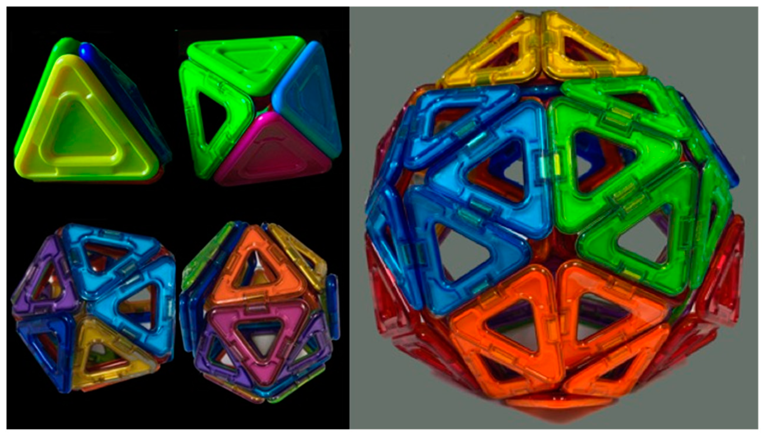
3. Radial Serial Folding
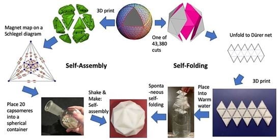
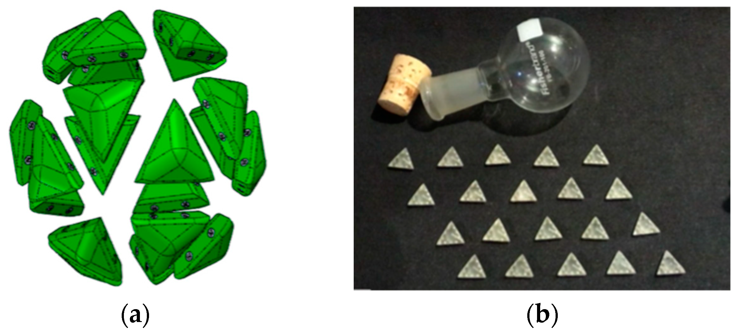
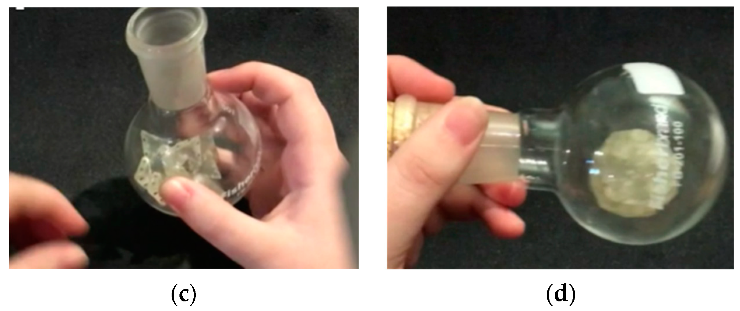
4. True Parallel Self-Assembly and Self-Folding
4.1. Parallel Self-Assembly
“thermodynamic self-assembly … involves the establishment of a kinetically rapid, reversible, thermodynamic equilibrium… which results in the energetically most stable product being formed in the greatest proportions. Because the equilibrium is reversible, the individual coordinate bonds need not form in the desired manner each and every time. Instead, the constant forming and reforming of bonds … results in ‘incorrect’ bonds being undone and associating ‘correctly’ under a thermodynamic impetus. Thermodynamic self-assembly therefore has the unique property of being ‘self-correcting.’ … the key to using this class of self-assembly as a synthetic tool is to ensure that the desired product will be more stable than any possible competing product. … the [more that] the desired product is selectively favored, the greater its stability relative to its competitors, the greater its proportion in solution”.
4.2. Parallel Self-Folding
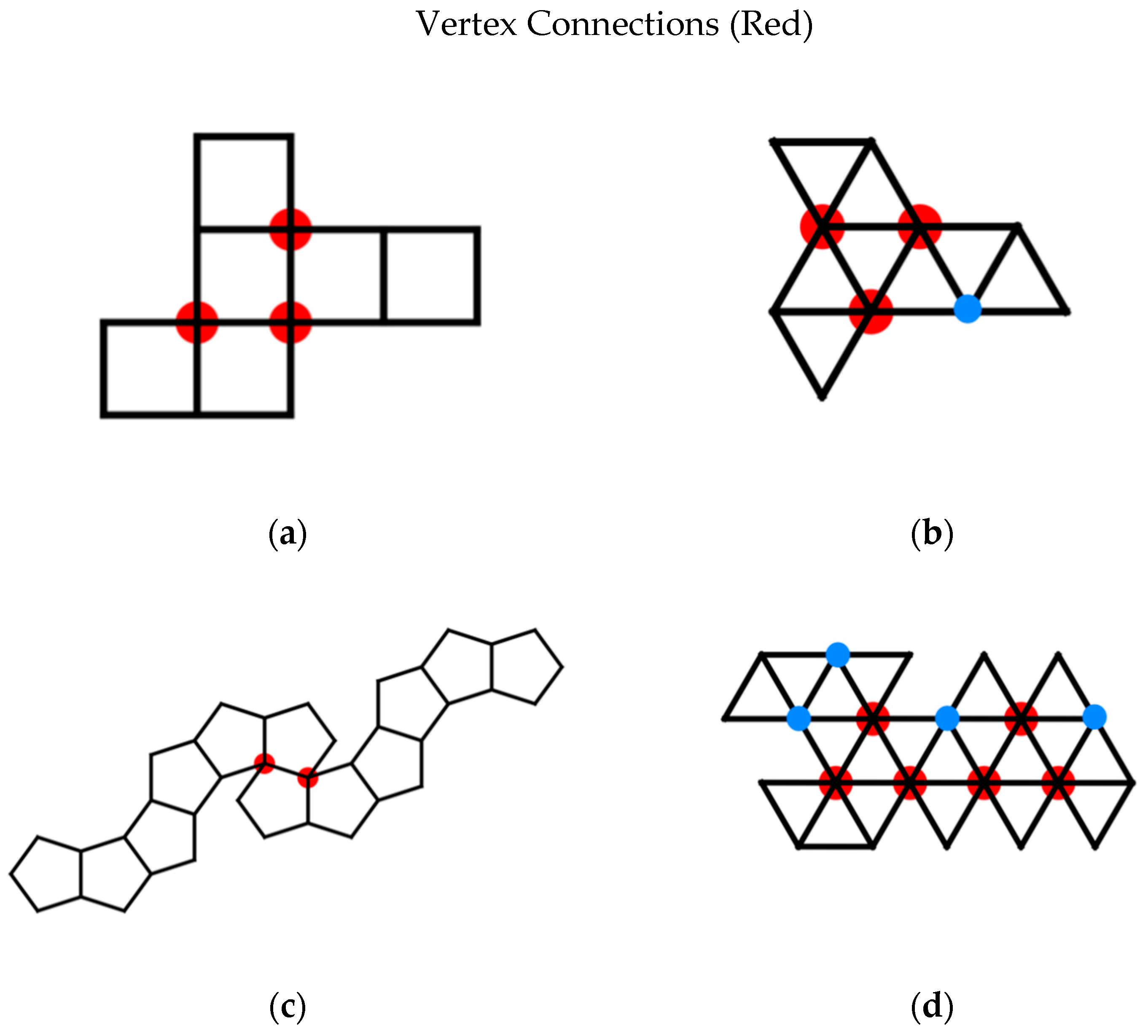
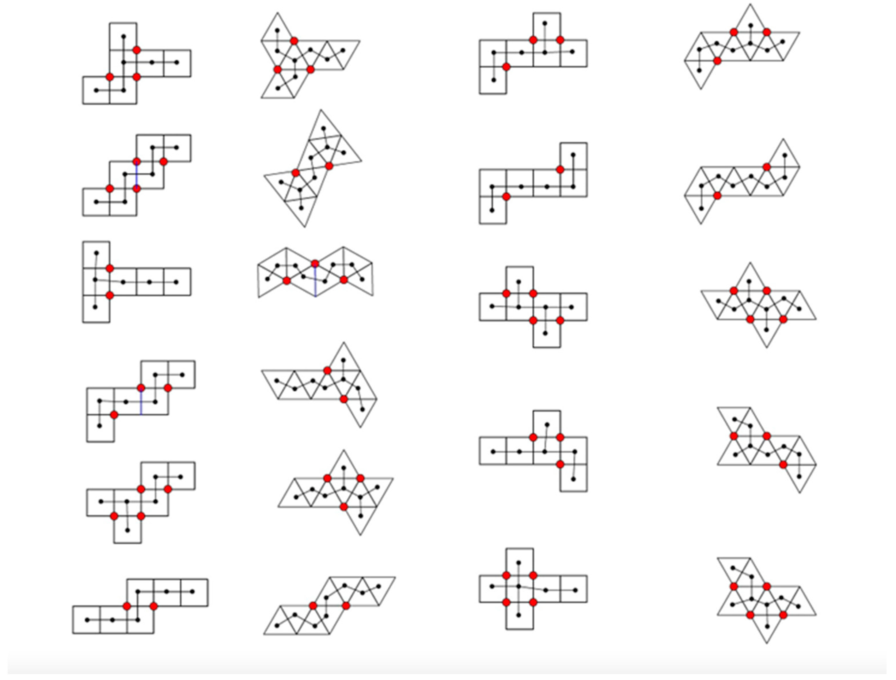
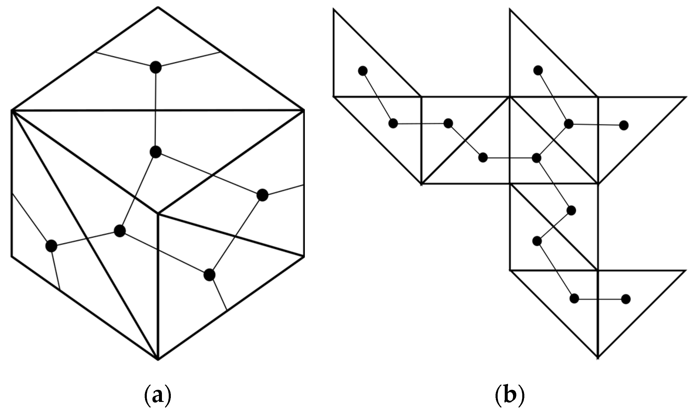
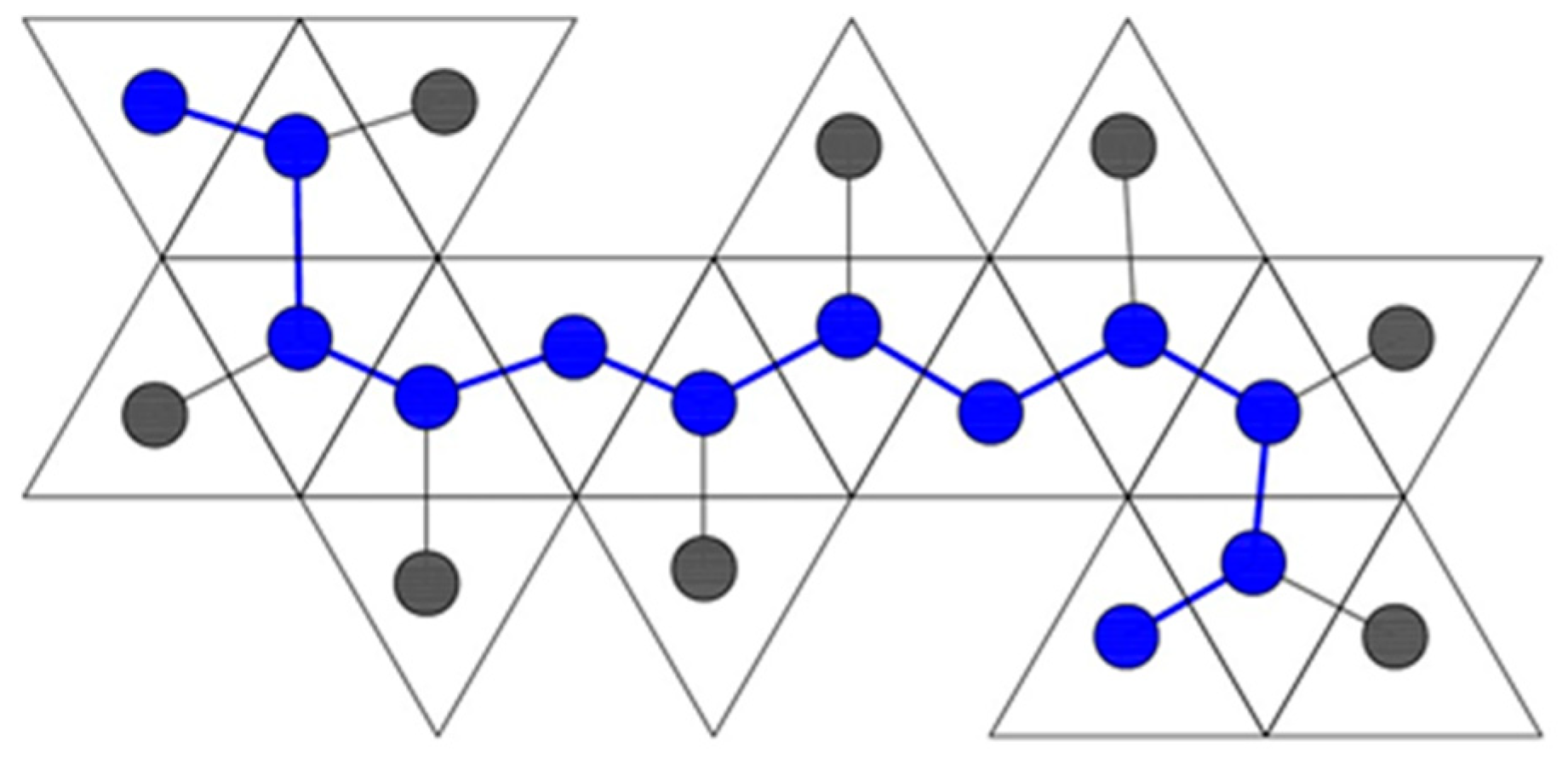
- vertex connections
- leaves
- length of spanning tree
- degree distribution
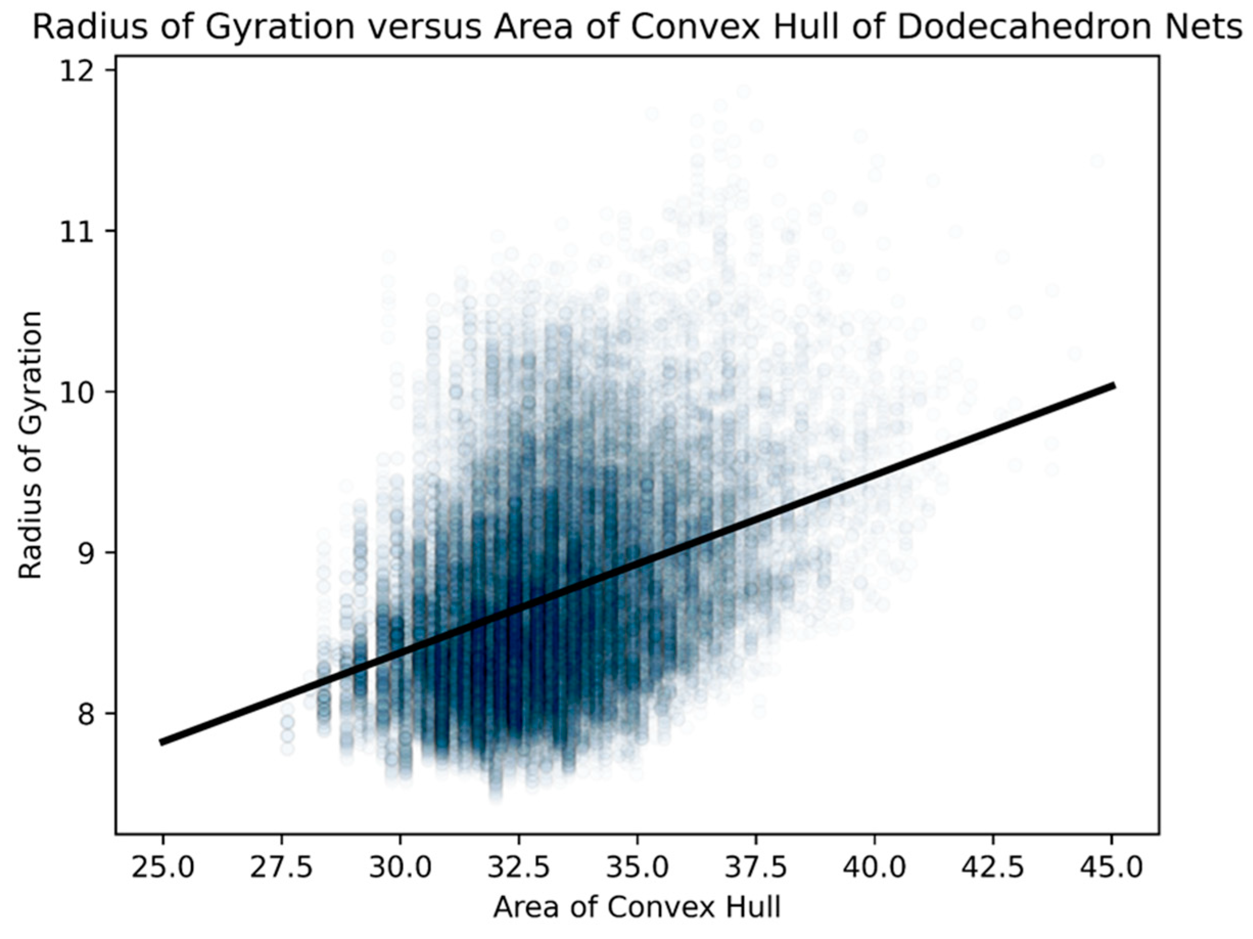
- area of a convex hull
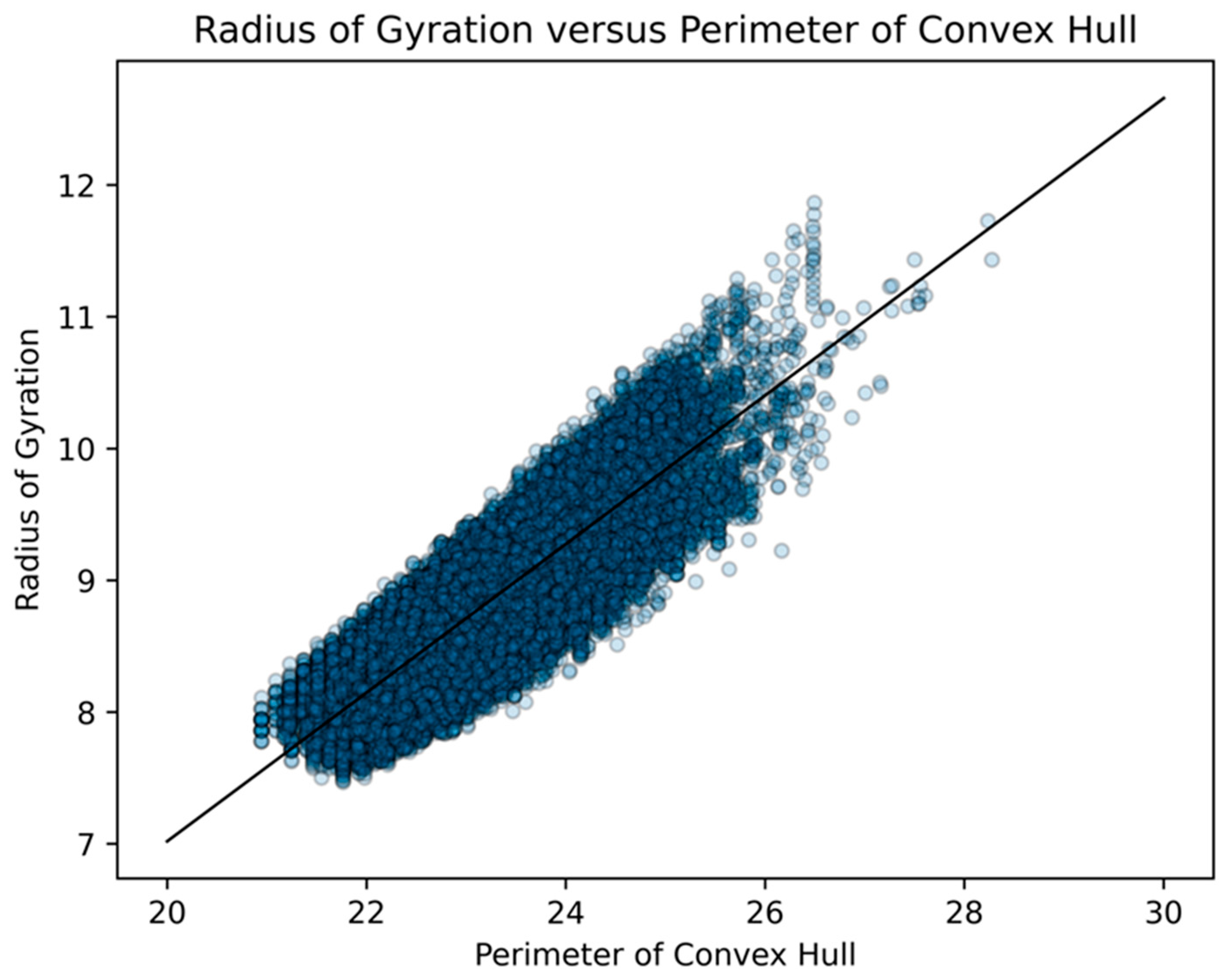
- perimeter of a convex hull
- radius of gyration
5. Random Folding
6. Conclusions
Supplementary Materials
Author Contributions
Funding
Data Availability Statement
Acknowledgments
Conflicts of Interest
References
- Pelesko, J. Self Assembly: The Science of Things That Put Themselves Together; Chapman and Hall: London, UK, 2007. [Google Scholar]
- Whitesides, G.M.; Grzybowski, B. Self-assembly at all scales. Science 2002, 295, 2418–2421. [Google Scholar] [CrossRef] [PubMed] [Green Version]
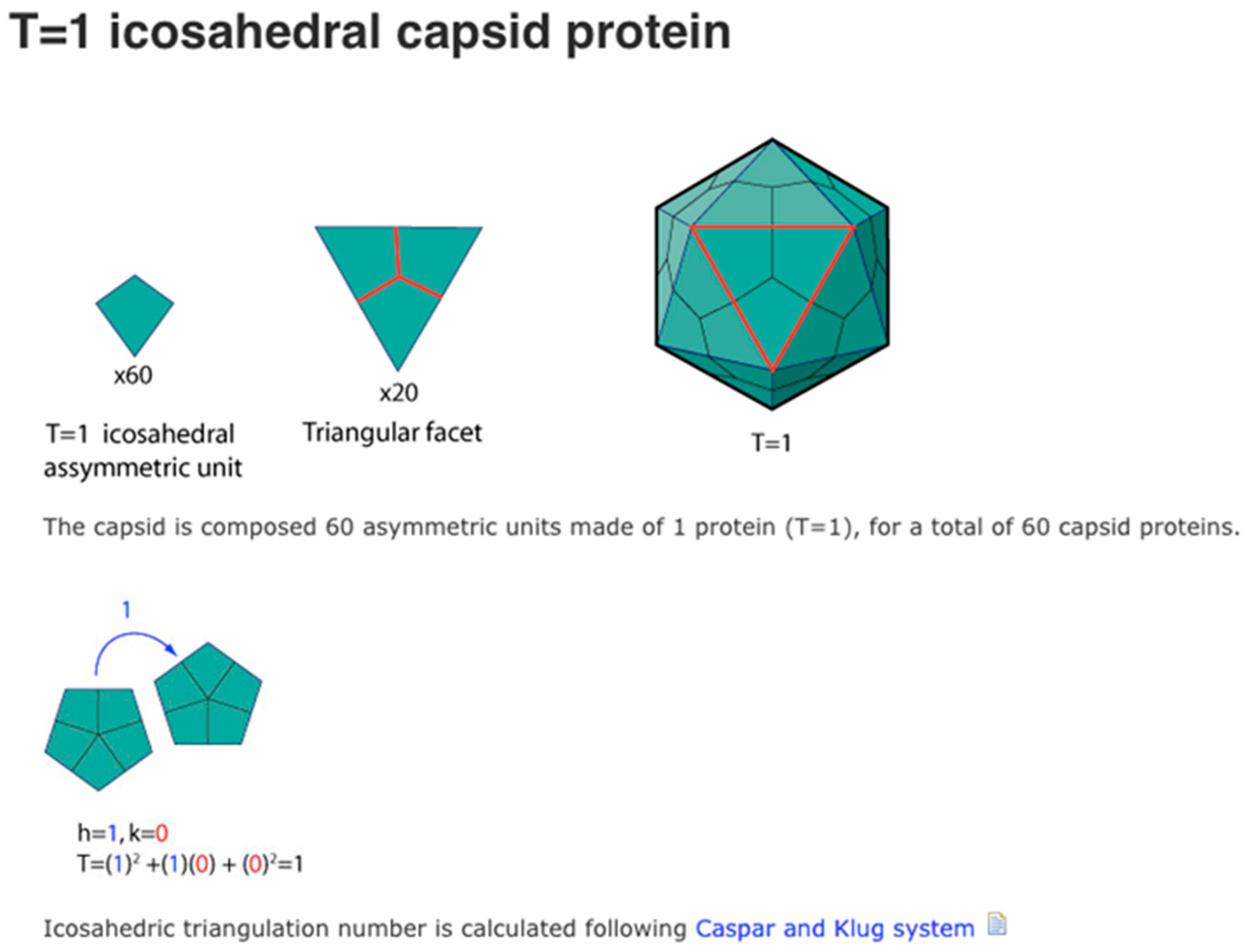
- Caspar, D.L.D.; Klug, A. Physical Principles in the Construction of Regular Viruses. Cold Spring Harb. Symp. Quant. Biol. 1962, 27, 1–24. [Google Scholar] [CrossRef] [PubMed]
- Berger, B.; King, J.; Schwartz, R.; Shor, P. Local rule mechanism for selecting icosahedral shell geometry. Discret. Appl. Math. 2002, 104, 97–111. [Google Scholar] [CrossRef] [Green Version]
- Twarock, R.; Bingham, R.J.; Dykeman, E.C.; Stockley, P.G. A modelling paradigm for RNA virus assembly. Curr. Opin. Virol. 2018, 31, 74–81. [Google Scholar] [CrossRef] [PubMed]
- Rycenga, M.; Camargo, P.H.C.; Xia, Y. Template-assisted self-assembly: A versatile approach to complex micro-and nanostructures. Soft Matter 2009, 5, 1129–1136. [Google Scholar] [CrossRef]
- Chung, W.-J.; Oh, J.-W.; Kwak, K.; Lee, B.Y.; Meyer, J.; Wang, E.; Hexemer, A.; Lee, S.-W. Biomimetic self-templating supramolecular structures. Nature 2011, 478, 364–368. [Google Scholar] [CrossRef] [PubMed]
- Jin, H.E.; Jang, J.; Chung, J.; Lee, H.J.; Wang, E.; Lee, S.W.; Chung, W.J. Biomi-metic self-templated hierarchical structures of collagen-like peptide amphiphiles. Nano Lett. 2015, 15, 7138–7145. [Google Scholar] [CrossRef]
- Sun, H.; Li, Y.; Yu, S.; Liu, J. Hierarchical self-assembly of proteins through rationally designed supramolecular interfaces. Front. Bioeng. Biotechnol. 2020, 8, 295. [Google Scholar] [CrossRef] [Green Version]
- Kim, N.H.; Choi, H.; Shahzad, Z.M.; Ki, H.; Lee, J.; Chae, H.; Kim, Y.H. Supramolecular assembly of protein building blocks: From folding to function. Nano Converg. 2022, 9, 4. [Google Scholar] [CrossRef]
- Tibbits, S. Things Fall Together: A Guide to the New Materials Revolution; Princeton University Press: Princeton, NJ, USA, 2021. [Google Scholar]
- Tibbits, S. Self-Assembly Lab: Experiments in Programming Matter; Routledge: New York, NY, USA, 2017. [Google Scholar]
- O’Rourke, J. How to Fold It: The Mathematics of Linkages, Origami, and Polyhedra; Cambridge University Press: New York, NY, USA, 2011. [Google Scholar]
- Iguchi, K. Exactly solvable model of protein folding: Rubik’s magic snake model. Int. J. Mod. Phys. B 1999, 13, 325–361. [Google Scholar] [CrossRef]
- Ding, X.; Lu, S. Fundamental reconfiguration theory of chain-type modular reconfigurable mechanisms. Mech. Mach. Theory 2013, 70, 487–507. [Google Scholar] [CrossRef]
- Liu, J.; Zhang, X.; Zhang, K.; Dai, J.S.; Li, S.; Sun, Q. Configuration Analysis of a Reconfigurable Rubik’s Snake Robot. Proc. Inst. Mech. Eng. Part C J. Mech. Eng. Sci. 2019, 233, 3137–3154. [Google Scholar] [CrossRef]
- Li, Z.; Hou, S.; Bishop, T.C. Computational Design and Analysis of a Magic Snake. J. Mech. Robot. 2020, 12, 054501. [Google Scholar] [CrossRef] [PubMed]
- Hou, S.; Chen, Y.; Li, Z. Some Mathematical Problems Related to the Rubik’s Snake. J. Mech. Robot. 2021, 13, 014502. [Google Scholar] [CrossRef]
- Magformers, LLC. Available online: https://www.loc8nearme.com/michigan/canton/magformers-llc/3031947/ (accessed on 1 December 2022).
- Palma, C.A.; Cecchini, M.; Samorì, P. Predicting self-assembly: From empiricism to determinism. Chem. Soc. Rev. 2012, 41, 3713–3730. [Google Scholar] [CrossRef]
- Jungck, J.R. Thermodynamics of Self Assembly: An Empirical Example Relating Entropy and Evolution. In Molecular Evolution: Prebiological and Biological; Rohlfing, D.L., Oparin, A.I., Eds.; Springer: Boston, MA, USA, 1972; pp. 101–109. [Google Scholar]
- Davenport, J.; Pique, M.; Getzoff, E.; Huntoon, J.; Gardner, A.; Olson, A. A self-assisting protein folding model for teaching structural molecular biology. Structure 2017, 25, 671–678. [Google Scholar] [CrossRef] [Green Version]
- Swiegers, G.F.; Sivakumar, B.; Junhua, H. Assemblies and Self-Assembly. In Reference Module in Chemistry, Molecular Sciences and Chemical Engineering; Reedijk, J., Ed.; Elsevier: Amsterdam, The Netherlands, 2016. [Google Scholar]
- Olson, A.J. Self-assembly gets physical. Nat. Nanotechnol. 2015, 10, 728. [Google Scholar] [CrossRef]
- Olson, A.J. Perspectives on structural molecular biology visualization: From past to present. J. Mol. Biol. 2018, 430, 3997–4012. [Google Scholar] [CrossRef]
- Olson, A.J.; Hu, Y.H.; Keinan, E. Chemical mimicry of viral capsid self-assembly. Proc. Natl. Acad. Sci. USA 2007, 104, 20731–20736. [Google Scholar] [CrossRef] [Green Version]
- Cook, T.R.; Vajpayee, V.; Lee, M.H.; Stang, P.J.; Chi, K.W. Biomedical and bio-chemical applications of self-assembled metallacycles and metallacages. Acc. Chem. Res. 2013, 46, 2464–2474. [Google Scholar] [CrossRef]
- Plante, D.; Nicole, B.; Stephen, B.; John, R.J. Submitted to Math Horizons; Mathematics Association of America: Washington, DC, USA, 2022. [Google Scholar]
- Dodd, P.M.; Damasceno, P.F.; Glotzer, S.C. Universal folding pathways of polyhedron nets. Proc. Natl. Acad. Sci. USA 2018, 115, 6690–6696. [Google Scholar] [CrossRef] [PubMed] [Green Version]
- Geraets, J.A.; Dykeman, E.C.; Stockley, P.G.; Ranson, N.A.; Twarock, R. Genome Organization in an RNA Virus Revealed via Graph-Theoretical Analysis of Tomographic Data. PLoS Comput. Biol. 2015, 11, e100414. [Google Scholar] [CrossRef] [PubMed] [Green Version]
- Menon, G.; Pandey, S.; Gracias, D.; Kaplan, R.; Johnson, D. Building polyhedra by self-assembly. Not. Am. Math. Soc. 2017, 67, 822–823. [Google Scholar]
- Pandey, S.; Ewing, M.; Kunas, A.; Nguyen, N.; Gracias, D.H.; Menon, G. Algorithmic design of self-folding polyhedra. Proc. Natl. Acad. Sci. USA 2011, 108, 19885–19890. [Google Scholar] [CrossRef] [PubMed] [Green Version]
- Kaplan, R.; Klobušický, J.; Pandey, S.; Gracias, D.H.; Menon, G. Building polyhedra by self-assembly: Theory and experiment. Artif. Life 2014, 20, 409–439. [Google Scholar] [CrossRef] [PubMed]
- Pilgrim, K.M.; Menon, G.; Sagan, B.; Strings, T.; Heitsch, C.; Kujawa, J.R. Building Polyhedra by Self-Assembly, Trees Strings, R.N.A. Folding; AMS Fall Sectional Sampler. 2017. Available online: https://community.ams.org/journals/notices/201708/rnoti-p816.pdf (accessed on 1 December 2022).
- Azam, A.; Leong, T.G.; Zarafshar, A.M.; Gracias, D.H. Compactness Determines the Success of Cube and Octahedron Self-Assembly. PLoS ONE 2009, 4, e4451. [Google Scholar] [CrossRef] [Green Version]
- Löthman, P.A.; Hageman, T.A.G.; Elwenspoek, M.C.; Krijnen, G.J.M.; Mastrangeli, M.; Manz, A.; Abelmann, L. A Thermodynamic Description of Turbulence as a Source of Stochastic Kinetic Energy for 3D Self-Assembly. Adv. Mater. Interfaces 2020, 7, 1900963. [Google Scholar] [CrossRef] [Green Version]
- Kuang, X.; Roach, D.J.; Wu, J.; Hamel, C.M.; Ding, Z.; Wang, T.; Dunn, M.L.; Qi, H.J. Advances in 4D printing: Materials and applications. Adv. Funct. Mater. 2019, 29, 1805290. [Google Scholar] [CrossRef]
- Abelmann, L.; Hageman, T.A.G.; Löthman, P.A.; Mastrangeli, M.; Elwenspoek, M.C. Three-dimensional self-assembly using dipolar interaction. Sci. Adv. 2020, 6, eaba2007. [Google Scholar] [CrossRef]
- Troisi, A.; Wong, V.; Ratner, M.A. An agent-based approach for modeling molecular self-organization. Proc. Natl. Acad. Sci. USA 2005, 102, 255–260. [Google Scholar] [CrossRef] [Green Version]
- Demoly, F.; André, J.C. Is order creation through disorder in additive manufacturing possible? Cogent Eng. 2021, 8, 1889110. [Google Scholar] [CrossRef]
- Mastrangeli, M.; Mermoud, G.; Martinoli, A. Modeling self-assembly across scales: The unifying perspective of smart minimal particles. Micromachines 2011, 2, 82–115. [Google Scholar] [CrossRef]


| Type of Organization | Pathway | Guided | Methods of Study | Biological Analogues |
|---|---|---|---|---|
| True Parallel Self-Folding and Self-Assembly | Parallel | No | Plastic, Nickel and Solder | Viral capsids, ribosomes |
| Serial Folding and Assembly | Serial | Yes | Origami | Viral capsids, proteins |
| Template-Assisted (Guided) Serial Folding | Serial | Yes | Origami; tethered plastic | RNA-tethered capsid assembly |
| Serial Self-Folding | Serial | No | 3D printed models in an oriented system | Protein Folding |
| Radial Serial Folding | Radial | No | Magformers | not yet known |
| Random Folding | Random | No | Turbulent Systems | in vivo cell conditions |
| Combinatorial Explosion | ||
|---|---|---|
| Polyhedron | Number of Faces | Number of Dürer Nets |
| Tetrahedron | 4 | 2 |
| Cube | 6 | 11 |
| Octahedron | 8 | 11 |
| Dodecahedron | 12 | 43,380 |
| Icosahedron | 20 | 43,380 |
| Viral capsid (T = 1) | 60 | ~1030 |
| Type | 1 | 2 | 3 | 4 | 5 | 6 | 7 | 8 | 9 | 10 | Avg |
|---|---|---|---|---|---|---|---|---|---|---|---|
| Cylindrical | 145 | 174 | 268 | 46 | 72 | 166 | 138 | 367 | 325 | 448 | 214.9 |
| Spherical | 58 | 67 | 44 | 97 | 84 | 116 | 86 | 16 | 81 | 28 | 67.7 |
| A | B | C | D | Nets of This Type |
|---|---|---|---|---|
| 2 | 4 | 0 | 0 | 4 |
| 3 | 2 | 1 | 0 | 5 |
| 4 | 0 | 2 | 0 | 1 |
| 4 | 1 | 0 | 1 | 1 |
| Shape | of Faces | of Unique Degree Distributions |
|---|---|---|
| Tetrahedron | 4 | 2 |
| Cube | 6 | 4 |
| Octahedron | 8 | 3 |
| Dodecahedron | 12 | 21 |
| Icosahedron | 20 | 9 |
Disclaimer/Publisher’s Note: The statements, opinions and data contained in all publications are solely those of the individual author(s) and contributor(s) and not of MDPI and/or the editor(s). MDPI and/or the editor(s) disclaim responsibility for any injury to people or property resulting from any ideas, methods, instructions or products referred to in the content. |
© 2022 by the authors. Licensee MDPI, Basel, Switzerland. This article is an open access article distributed under the terms and conditions of the Creative Commons Attribution (CC BY) license (https://creativecommons.org/licenses/by/4.0/).
Share and Cite
Jungck, J.R.; Brittain, S.; Plante, D.; Flynn, J. Self-Assembly, Self-Folding, and Origami: Comparative Design Principles. Biomimetics 2023, 8, 12. https://doi.org/10.3390/biomimetics8010012
Jungck JR, Brittain S, Plante D, Flynn J. Self-Assembly, Self-Folding, and Origami: Comparative Design Principles. Biomimetics. 2023; 8(1):12. https://doi.org/10.3390/biomimetics8010012
Chicago/Turabian StyleJungck, John R., Stephen Brittain, Donald Plante, and James Flynn. 2023. "Self-Assembly, Self-Folding, and Origami: Comparative Design Principles" Biomimetics 8, no. 1: 12. https://doi.org/10.3390/biomimetics8010012