1. Introduction
Inhalation of welding fume (WF) is a known cancer-causing agent for workers who undertake welding tasks [
1]. WF is generated during welding activities and is normally observed by the human eye as smoke originating from the arc site. Temperatures at the arc are above the boiling point of metals contained within the host material and welding consumables. The superheated metal vaporizes and then condenses into very fine particles (0.001–1 µm in diameter). The very fine particles are referred to as ‘fume’ and are readily inhaled [
2]. Worker exposure to WF has been shown to regularly exceed the applicable workplace exposure standard, potentially overexposing workers to known cancer-causing agents [
3].
There is a lack of freely available scientific information that is readily understood by end users (welders) and supervisors. Although research literature exists, few studies provide information that is accessible and transferrable to the workplace. Namely, which commonly used welding techniques produce the most fumes and how do common controls perform? Personal exposure sampling is a valuable tool to inform this, but empirical data suggests that very few businesses undertake sampling in a systematic manner to evaluate these questions.
It was found that there is a lack of peer-reviewed studies that compare welding techniques according to standardized protocols. There are a few [
4] studies that found direct comparison between the exposure levels of weld fumes for each welding technique. Where research on techniques did exist, exposure assessment was often undertaken by a variety of methods, including biomonitoring [
5] and exhaled breath condensate (EBC) techniques [
6] in addition to conventional air monitoring.
Notably, a recent study [
7] was conducted that compared control measures for hand-guided GMAW only. Comparisons between no ventilation, manually guided LEV hood and on-torch extraction were used. Arcing times of between 29 and 52 min, with an average of 42 min/test were used. An adjustment for the arc time: sample time ratio was made, but all results were presented unadjusted. Total welding fume and manganese were used for most of the estimates, as these were present at the highest concentrations. The use of on torch extraction resulted in a reduction of welding fume exposure by 70% and of manganese concentrations by 88%; the use of capture hoods reduced welding fume exposure by 88% and respirable manganese concentrations by 88%.
The determinants of occupational exposure to metals by gas metal arc welding and risk management measures were examined [
8]. The authors utilized biomonitoring techniques to compare levels of chromium, nickel and manganese caused by weld fumes in metal inert gas (MIG) welding. The findings showed that welding parameters (nature of the base metal and welding technique) and working conditions (confinement, welding and grinding durations, mechanical ventilation, and welding experience) could be predictive of occupational exposure levels.
In evaluating the operational parameters’ role in the emissions of fumes, the effects on the reduction of fume emissions in shielded metal arc welding (SMAW) were investigated [
8]. Air monitoring techniques were used, and it was found that emissions can be decreased by using the lowest voltage and amperage and the highest travel speed to the extent that it does not compromise weld quality.
The aim of this current study is to compare the effectiveness of control measures to assist in preventing welding fume exposure to workers. This project consisted of the following objectives:
Based on the literature review, develop a test protocol.
Undertake airborne sampling for welding fumes using welding techniques and consumables commonly found within the industry.
Compare welding fume concentrations across a range of commonly used welding techniques.
Compare welding fume concentrations for commonly used engineering controls.
Evaluate the effectiveness of welding powered air purifying respirators (PAPR).
Compare the metal composition of the welding fume for the test scenarios.
The common welding techniques being considered in this study are as follows:
Metal inert gas (MIG), also known as gas metal arc welding (GMAW)
Tungsten inert gas (TIG), also known as gas tungsten arc welding (GTAW)
Flux-cored arc welding (FCAW)
Manual metal arc welding (MMAW) (also known as stick or shielded metal arc welding/SMAW)
2. Materials and Methods
2.1. Overview
There is no directly applicable, standardized and accepted method for the sampling and analysis of welding fume that aligned directly with the study aims. Fume emission studies typically conform to ISO 15011-1 [
9] (and/or American Welding Society F1.2) methods for evaluating emissions from arc welding, which generally include robot welding and/or short duration (i.e., ≤1 min) welding inconsistent with industry practice [
10,
11]. Utilizing a test enclosure to assess WF was identified within very few papers, therefore, a custom method was generated by drawing principles from other accepted methods (
Table 1).
The incorporation of these methods led to a study design that was inexpensive, easily replicated, and minimized potential effects from environmental conditions. A welder was set up to weld inside a test enclosure (3.5 m × 8 m × 4.5 m). The welder was asked to weld using four different processes (metal inert gas (MIG), flux core arc welding (FCAW), manual metal arc (MMA) and tungsten inert gas (TIG). During all welding activities the welder was protected from welding fumes with respiratory protection. The workpieces for the study were 300 mm × 60 mm × 5 mm flat plate sections welded in pairs to construct 90° T-sections on the long edge and then combined to form an I-shaped section. Four different control measures were used for each process (no controls, on gun extraction, LEV hood capture, PAPR) (
Table 2), applied in a random sequence/welding process and replicated 3 times. As there are no commercially available on-gun extraction devices for use with MMA or TIG welding in Australia, hence this exposure control was not included in the study design.
The same welder was used to collect the required welding data to ensure consistent welding practices throughout. The general methodology followed each day of sampling was as follows:
Daily check completed, including enclosure checks (real-time monitoring and indoor air quality meter), risk management and welder check-in.
Enclosure set up by welder and researcher
Setup of welding equipment and consumables
Set up monitoring equipment
Commencement of sample run. Air horns were used to signal commencement of welding (i.e., long hold on horn for commencement)
During pause in welding—visual and verbally check in with welder.
Due to the limited visibility of the protective screening, most communication to workers was through hand gestures during sample runs.
Completion of sample run.
Air horns were also used to signal completion of sample period (i.e., short hold on horn for completion)
After sample run was completed, welder was instructed to leave welding helmet on and exit the enclosure.
Welder exits enclosure. Pumps stopped and data/details recorded.
The welder has a break whilst the researcher opens enclosure and ventilates (fans on, doors open)
The researcher supervised all test runs and provided instruction to the welder on when to commence/stop welding. Visual observation from outside the enclosure was not possible, thus video recordings using a GoPro camera were taken for each test. This allowed for post-hoc review, as necessary.
2.2. Variations in Methodology
Though every effort was made to ensure a consistent methodology across the four welding techniques implemented some variations in methodology occurred because of the chosen technique. During the TIG welding process, small additions to the methodology included the occasional changing or sharpening of the tungsten electrode and the replacement of the filler rod as required. During the MMA welding process, the electrode was changed out after approximately 120 mm of use. During the MIG and FCAW welding processes, the gun tip was cleaned at the end of each weld run. Occasionally, the tip was changed out.
2.3. Aerosol Sampling
During each sample run, four (4) individual welding fume samples were obtained. These samples were positioned in the following ways on or near the worker:
IOM inhalable sample positioned inside the welding helmet at breathing zone (In PAPR),
IOM inhalable sample fixed to the outside of the helmet in breathing zone (Out PAPR),
IOM inhalable sample positioned on lapel of worker (Lapel), and
IOM inhalable sample positioned 1 m horizontally from the welders’ station (static near field)
2.4. Real Time Aerosol Monitoring
TSI® AM520i SidePak™ Aerosol Monitors (AM520i) (TSI, Shoreview, MN, USA) fitted with PM10 impactors (TSI, Shoreview, MN, USA) were worn by the welder during the sampling runs. Real time monitoring using a laser light scattering approach was employed to obtain detection limits of 0.001 mg/m3, which is considerably lower than that achievable by gravimetric sampling given the relatively short run times. These instruments are fitted with a 650 nm laser diode which provides a detectable particle size range of 0.1 to 10 µm. One instrument was positioned to sample from the lapel of welder outside of the visor, while the other instrument was positioned with a small nylon probe entering the breathing zone under the visor to sample aerosol inside the visor adjacent to the cheek. During periods of sampling the welder was permitted to behave as normal, with no adjustments to the sampling equipment. Consequently, the results obtained are indicative of the effective protection factor.
The-real time monitors were all time synchronized to the PC clock time and configured to log the 1-s integrated average. All instruments were within calibration, as specified by the manufacturer. The flow rate of each unit was checked and adjusted using a secondary flow calibrator to the value specified by the manufacturer to best measure the aerosol size fraction. The units were zeroed prior to use, using the supplied HEPA filter (TSI, Shoreview, MN, USA). All real time monitors were operated with their factory default calibration factor (1) applied as results were not compared to gravimetric data, only for inside/outside comparisons.
2.5. Welding Fume—Sampling and Analysis
Gravimetric welding fume sampling was undertaken in accordance with AS 3853.1-2006 [
14]. Samples were collected on 25 mm diameter 5 µm PVC membrane filters for the duration of the sampling run only.
Gravimetric analysis of all samples was performed by GCG Health Safety & Hygiene, (Townsville, Australia), National Association of Testing Authorities (NATA) accreditation number 16791. Filters were analyzed for individual metals using inductively coupled plasma-mass spectrometry (ICP-MS) by MPL Laboratory (Perth, Australia), NATA accreditation number 2901. This method was selected as it has a detection limit for metals of interest up to 1000× lower than conventional inductively coupled plasma-optical emission spectrometry (ICP-OES) or graphite furnace atomic absorption spectroscopy (GF-AAS). The list of analytes is listed in
Table 3, along with the limits of quantitation (LOQ).
2.6. Data Analysis
The paired real-time aerosol monitoring files from the inside and outside samples were downloaded using TSI
® TrakPro5 (TSI, Shoreview, MN, USA) software and exported as CSV files to Microsoft Excel for postprocessing. The time stamp from each paired run was synchronized with each other and with video footage of the run and leading or trailing measurements removed, to create a matched data file. These files were imported into Stata v17.1 (StataCorp LLC., College Station, TX, USA) [
15] for analysis.
Individual welding fume sample data and determinants of exposure (i.e., welding process, exposure control, sampler location) were exported into Stata v17.1 [
15] for descriptive statistics and censored (Tobit) regression analysis [
16].
For analysis and visualization, all censored results from real-time or gravimetry were assigned a censored tag and all censored results were left at the limit of quantitation.
The Effective Protection Factor (EPF) is a measure of the protection provided by a properly selected, fit-tested, and functioning respirator when it is worn for only a fraction of the total exposure period in the workplace [
17]. EPF is the ratio of the contaminant concentration outside the respirator to that in the air inhaled. It is determined by sampling outside the respirator and in the breathing zone during the total exposure period, regardless of whether the respirator is being worn. The 5th percentile of protection factor results are used for comparison to respiratory protective device standards, being a conservative assessment of performance.
Paired samples from gravimetric and real time aerosol results were used to calculate Effective Protection Factors based on both measurement types.
where C_i = Concentration inside the respirator, C_o = Concentration outside the respirator.
Individual samples where the outside concentration (C_o) was less than 5 mg/m
3 were not included in the analysis as per recommendations [
17]. This value was calculated from the formula:
where: RMPF = 50 (Required Minimum Protection Factor for Powered Air Purifying Respirator (PAPR) with Class PAPR-P3 particulate filter with any head covering), C_i Analytical LOQ = 0.001 mg/m
3 (Lower limit of detection range of TSI
® AM520i SidePak™ Aerosol Monitor).
The distribution of individual protection factor measurements is not normally distributed preventing the use of common statistical methods. Non-parametric methods which do not rely on assumptions of normally distributed data were used.
2.7. Quality Control
To ensure quality of the control data multiple checklists were followed. Daily checklists were used to ensure the conditions, equipment and subject were in a consistent condition from day to day. Each test run was accompanied by a test record sheet noting test type/control/test checks and test observations including ambient conditions, LEV performance and welder behavior. Additionally, real time monitors were zero calibrated and flow calibrated prior to each sample run. Gravimetric sampling equipment was calibrated according to NATA requirements and GCG procedures. Analytical sample field blanks were compiled according to AS 3853.1-2006 [
14]. All tests were performed under supervision of the field researcher.
3. Results and Discussion
3.1. Conditions during Tests
Several conditions were monitored during each test inside the chamber to ensure environmental conditions remained at a level where variables is limited. Conditions remained largely constant across all tests (
Table 4). The face velocity of the Nederman N24 Wall Mounted Local Extraction Ventilation System (Nederman Corporation, Helsingborg, Sweden) was initially measured at 3.11 m/s and this performance was maintained without change throughout the project.
Performance of the Translas W100 On Torch Extraction Unit (Translas, Nieuwegein, The Netherlands) was measured at the 4 ports on the torch with the following results (
Table 5) and was maintained throughout the project by the devices airflow control unit:
The differences between lapel and outside PAPR results are considerable and the most common position for sampling worker exposure to aerosols is on the lapel. However, for welding, placing the sampler inside the welding helmet is recommended [
14]. In the case of powered air purifying respirators incorporated into welding helmets, this recommendation becomes impractical with conventional samplers and general suggestions are to place the sampler head in the lapel as close as possible to the welding shield. One source of potential bias in this approach is the local dilution from air washed out of the flexible seal of the helmet around the chin and neck. The results collected in this study may be affected by this source of bias; however, the practical impact of this bias is considered to be negligible.
Near-field results (1 m from the welder) exhibited concentrations approaching those found directly outside the welding helmet, consistent with previous results [
18,
19]. These results have implications for welders’ assistants (TAs), who are often in proximity to welding activities. Respiratory protection requirements for these workers can be overlooked, while exposures may be significant depending on the location and work involved.
3.2. Welding Fume and Metal Concentrations
The mean concentrations/type/control and location for 123 separate sampling runs are presented in
Table 6. The average sampling run was 48.25 min, with a range from 36 to 67 min. Results for total welding fume, iron and manganese are presented as these three contaminants had the greatest number of uncensored concentrations (above the laboratory LOQ). Filtering results by application of the minimum outside concentration as used in the real-time data was not possible for the gravimetric welding fume and metal concentrations, as all concentrations were below the calculated minimums.
Samples collected inside the 3M™ Speedglas™ Adflo™ Powered Air Purifying Respirator (3M™, Gagnef, Sweden) showed 61% of total welding fume results were censored, 97% of iron results were censored and 94% of manganese results were censored. This indicates welding fume and metal concentrations inside the respirator were low to very low for most of the sampling runs.
Samples were analyzed for a range of other metals, including the International Agency for Research on Cancer (IARC) Group 1 carcinogens beryllium, cadmium and nickel. Hexavalent chromium (CrVI) is also an IARC Group 1 carcinogen, but samples were analyzed for total chromium for a number of reasons, including the fact that mild steel and not stainless steel were used as the filler or base metal for all processes except TIG and an additional set of samples specific for CrVI analysis would be required. One hundred percent of samples collected inside the 3M™ Speedglas™ Adflo™ Powered Air Purifying Respirator for beryllium, cadmium, chromium and nickel were less than the laboratory quantitation limit (LOQ).
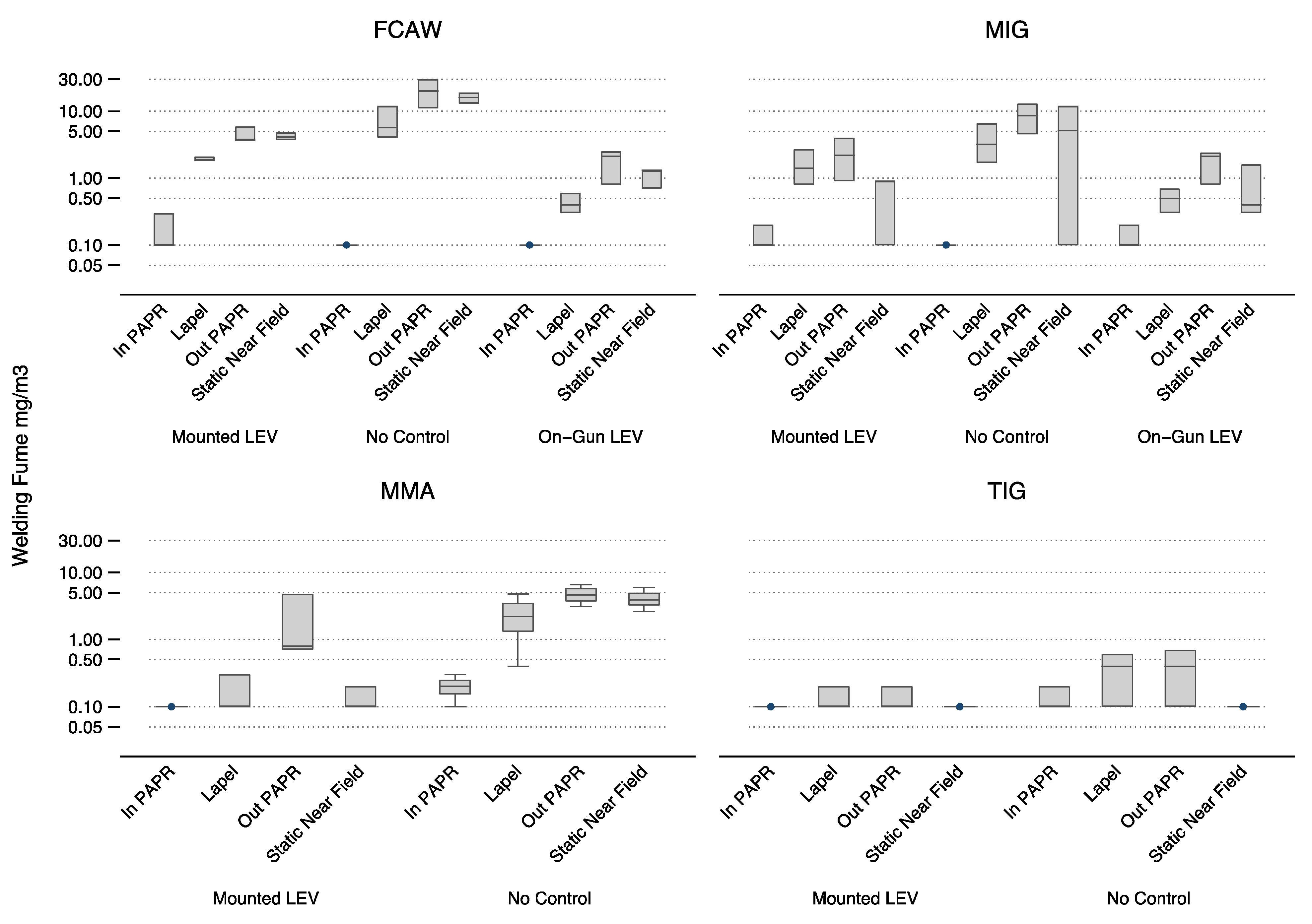
Total welding fume results are plotted in
Figure 1, showing that the relationship between welding type and fume concentrations varies by the location of sampling and the effectiveness of the fume control method employed. For FCAW and MIG, the use of Translas on-gun fume extraction resulted in markedly lower concentrations than the use of LEV hood capture, whereas an overall trend was displayed where samples collected on the lapel were lower than those collected on the outside of the 3M™ Speedglas™ welding helmet (out PAPR). This is a characteristic of welding fume exposure measurements, which often display an asymmetry depending on the position of the welder’s head in relation to the weld.
3.3. PAPR Effective Protection Factors Based on Metal Concentrations
The minimum protection factor provided by the 3M™ Speedglas™ Adflo™ was calculated using the measured concentrations of the welding fume, iron and manganese in the in PAPR samples and the lapel samples, where the lapel samples were >5 mg/m
3. Since the majority of in PAPR samples were <LOQ, the calculated protection factors represent the lowest possible protection factor; therefore, the majority of EPFs reported in
Table 7 are greater than (>) the calculated result.
3.4. Effective Protection Factors Based on Real-Time Aerosol Concentrations
A total of 6712 1-s measurements were collected from four welding methods for three different control types. The effective protection factor provided by the 3M™ Speedglas™ Adflo™ Powered Air Purifying Respirator during each of these conditions was calculated. Results were aggregated across 12 runs by welding type and control type to obtain sufficient data for the protection factor calculations (
Table 8). The first and last 10 s of each sample were clipped to remove sources of bias from donning and doffing, and in accordance with previous recommendations [
17], only samples where the outside concentration was greater than 5 mg/m
3 were used.
This limited the calculations to samples obtained from FCAW, MIG and MMA welding types only; TIG welding activities did not generate aerosol concentrations greater than the minimum outside concentration. Results from Run 10 (MIG–PAPR Control) were removed from the analysis after observing an instrument error in the real-time data.
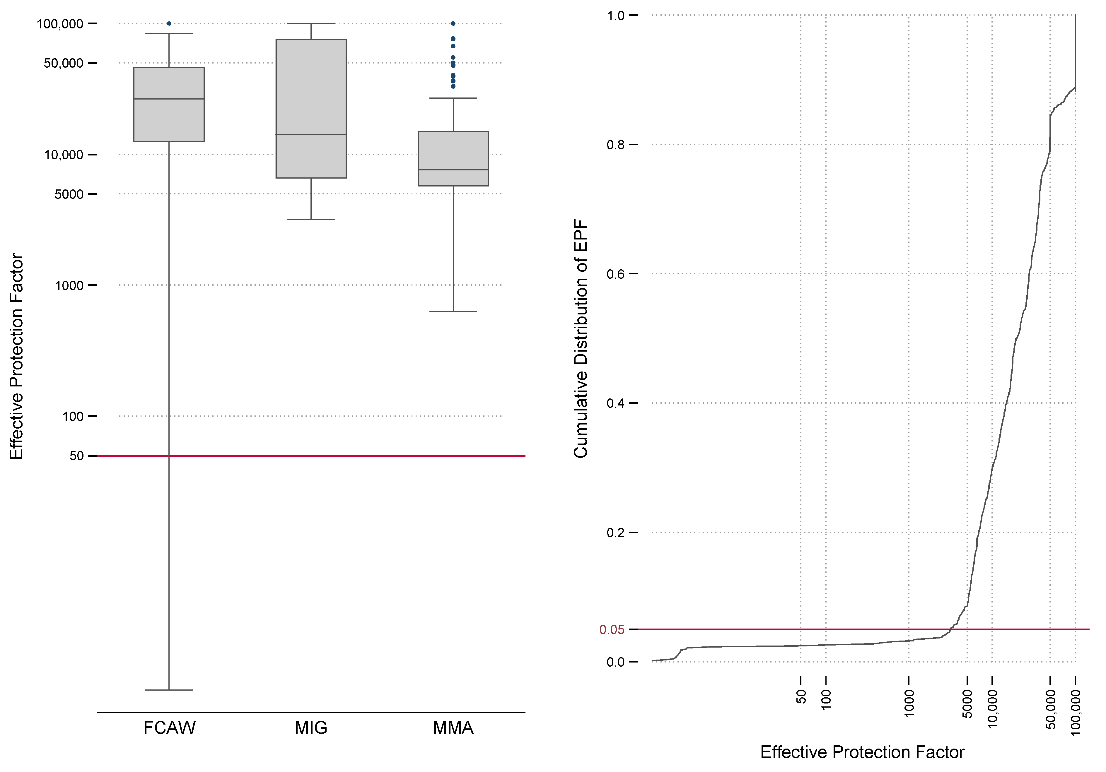
The 5th percentile of the effective protection factor provided by the 3M™ Speedglas™ Adflo™ Powered Air Purifying Respirator for all sampled welding activities was considerably greater than the required minimum protection factor (RMPF) of 50 specified [
20] for a powered air purifying respirator (PAPR) with a class PAPR-P3 particulate filter with any head covering. Results ranged from 2600 to 4100 (rounded to two significant figures), indicating a level of performance at least 52× better than the current Australian and New Zealand standards. The overall distribution of protection factors regardless of the welding type demonstrates the consistency of protection factors and the probability that regardless of the type of welding being conducted, the protection afforded by the Speedglas™ Adflo™ Powered Air Purifying Respirator is well above the minimum standards. It should be noted that boilermakers may perform different types of welding during a single day, so plotting all the EPFs of different welding types together should be considered representation of potential exposure.
The effective protection factors by welding type and the aggregated distribution of all effective protection factors were combined (
Figure 2). The AS/NZS RMPF of 50 is shown on the box-whisker plot for comparison, as is the 5th percentile of the cumulative distribution.
3.5. Determinants of Exposure Analysis
The effects of individual controls on total gravimetric welding fume concentrations were assessed using a censored linear regression method (tobit regression). This provides a linear estimate of the effects of different controls on welding fume relative to a 1-unit change in the base case. In relation to ventilation controls, the base case was “No Control”, and in relation to sampling location, the base case was “Inside the PAPR”.
The results of the model indicate that compared to no controls during FCAW, the use of LEV hood capture would reduce concentrations by an average factor of 8.9, whereas using on-gun LEV would reduce concentrations by an average factor of 12.4. Both reductions are highly statistically significant (
Table 9). Similarly, using on-gun LEV control for MIG welding would result in an average reduction factor of 3.9 compared to 3.6 by using LEV hood capture. These results indicate that on-gun LEV results in lower welding fume exposure than the use of LEV hood capture in this study.
The location of samplers outside of the PAPR clearly showed the differences in concentrations in relation to their positioning and the fume emission quantities by type. Importantly, the static near-field concentration is potentially greater than lapel concentrations in areas of restricted ventilation, such as the test booth. Boilermakers’ assistants are often present nearby during welding activities, and in such conditions they should be provided with similar levels of protection, a finding also made by Cena [
21].
4. Conclusions
The results of the real-time aerosol monitoring returned 5th percentile effective protection factors of the 3M™ Speedglas™ Adflo™ for all sampled welding activities, which is considerably greater than the required minimum protection factor of 50 specified in AS/NZS 1715:2009 for powered air purifying respirators (PAPRs) with class PAPR-P3 particulate filter with any head covering. Results ranged from 2600 to 4100 (rounded to two significant figures), indicating a level of performance at least 52× better than the current Australian and New Zealand standards. Protection factors calculated using gravimetric methods were hampered by low outside concentrations, despite the test enclosure providing limited ventilation. The results obtained indicated protection factors were likely to be greater than 50, but they showed the difficulty of attempting to measure workplace protection factors using conventional analytical techniques in the absence of high exposures.
The protection factor against gaseous components of welding emissions, such as ozone, was not measured in this study. The presence and concentration of other components of welding emissions should be considered when selecting respiratory protection in conjunction with other elements of the hierarchy of control.
Compared to using no controls, in our study, LEV hood capture showed a reduction in welding fume concentrations in the breathing zone of a welder by up to a factor of 9. The use of on-gun LEV reduced welding fume concentrations in the breathing zone of a welder by up to a factor of 12. These findings are in agreement with previous findings [
7], adding to the evidence demonstrating the benefits of on-gun extraction. It is believed that this improvement is due to the source of extraction being closer to the weld pool and being able to be maintained at a close distance without additional effort by the welder. This is an ability not possible with conventional hood capture LEV in normal welding workshops, which require the hood to be moved regularly to maintain a position within the zone of influence, a behavior we note is not always adhered to in the real world.
Near-field (1 m) exposures to welding fume are of a similar concentration to those measured directly outside the welding helmet. This may have implications for the respiratory protection requirements for welders’ assistants who spend time near welding activities, particularly high-emission processes such as the FCAW.
Author Contributions
Conceptualization, D.B.; methodology, D.B. and P.K.; validation, P.K. and R.K.; formal analysis, P.K.; investigation, G.C.; resources, G.C. and D.B.; data curation, P.K., G.C. and D.B.; writing—original draft preparation, P.K. and R.K.; writing—review and editing, P.K. and R.K.; visualization, P.K.; project administration, D.B.; funding acquisition, D.B. All authors have read and agreed to the published version of the manuscript.
Funding
This research was funded by Apex Welding Safety (AWS).
Institutional Review Board Statement
The study was conducted in accordance with the Declaration of Helsinki and approved by the Human Research Ethics Committee of Central Queensland University (protocol code 0000024085 12/04/2023).
Informed Consent Statement
Informed consent was obtained from all subjects involved in the study.
Data Availability Statement
The data presented in this study are available upon request from the corresponding author. The data are not publicly available due to privacy reasons.
Conflicts of Interest
The authors declare no conflict of interest. The funders helped to design the study by providing information on welding practices common to Australia and provided the equipment used in the study. However, they had no role in the collection, analyses, or interpretation of data; in the writing of the manuscript; or in the decision to publish the results.
References
- Guha, N.; Loomis, D.; Guyton, K.Z.; Grosse, Y.; El Ghissassi, F.; Bouvard, V.; Straif, K. Carcinogenicity of welding, molybdenum trioxide, and indium tin oxide. Lancet Oncol. 2017, 18, 581–582. [Google Scholar] [CrossRef] [PubMed]
- Berlinger, B.; Benker, N.; Weinbruch, S.; L’Vov, B.; Ebert, M.; Koch, W.; Thomassen, Y. Physicochemical characterisation of different welding aerosols. Anal. Bioanal. Chem. 2011, 399, 1773–1780. [Google Scholar] [CrossRef] [PubMed]
- BAuA (Federal Institute for Occupational Safety and Health). Technical Rule for Hazardous Substances (TRGS) 528: Welding Work 2020; Committee on Hazardous Substances: Berlin, Germany, 2020. [Google Scholar]
- Keane, M.J. An Evaluation of Welding Processes to reduce Hexavalent Chromium Exposures and reduce Costs by Using Better Welding techniques. Environ. Health Insights 2014, 8, 47–50. [Google Scholar] [CrossRef] [Green Version]
- Stanislawska, M.; Janasik, B.; Kuras, R.; Malachowska, B.; Halatek, T.; Wasowicz, W. Assessment of occupational exposure to stainless steel welding fumes—A human biomonitoring study. Toxicol. Lett. 2020, 329, 47–55. [Google Scholar] [CrossRef] [PubMed]
- Riccelli, M.G.; Goldoni, M.; Andreoli, R.; Mozzoni, P.; Pinelli, S.; Alinovi, R.; Corradi, M. Biomarkers of exposure to stainless steel tungsten inert gas welding fumes and the effect of exposure on exhaled breath condensate. Toxicol. Lett. 2018, 292, 108–114. [Google Scholar] [CrossRef] [PubMed]
- Lehnert, M.; Goebel, A.; Zschiesche, W.; Kendzia, B.; Pelzer, J.; Taeger, D.; Behrens, T. How to Reduce the Exposure of Welders to an Acceptable Level: Results of the InterWeld Study. Ann. Work. Expo. Health 2022, 66, 192–202. [Google Scholar] [CrossRef] [PubMed]
- Sajedifar, J.; Hossein, A.; Kokabi, A.H.; Dehghan, S.F.; Mehri, A.; Azam, K.; Golbabaei, F. Evaluation of operational parameters role on the emission of fumes. Ind. Health 2018, 56, 198–206. [Google Scholar] [CrossRef] [PubMed] [Green Version]
- ISO 15011-1; Health and Safety in Welding and Allied Processes—Laboratory Method for Sampling Fume and Gases—Part 1: Determination of Fume Emission Rate during Arc Welding and Collection of Fume for Analysis. ISO: Geneva, Switzerland, 2009.
- Brand, P.; Ebert, B.; Esser, A.; Sharma, R. Direct Exposure of Welders to Welding Fumes and Effect of Fume Extraction Systems Under Controlled Conditions. J. Occup. Environ. Med. 2021, 63, 490–502. [Google Scholar] [CrossRef] [PubMed]
- Keane, M.J.; Siert, A.; Chen, B.T.; Stone, S.G. Profiling mild steel welding processes to reduce fume emissions and costs in the workplace. Ann. Occup. Hyg. 2014, 58, 403–412. [Google Scholar] [CrossRef] [PubMed] [Green Version]
- AWS F1.2:2013; Laboratory Method for Measuring Fume Generation Rates and Total Fume Emission of Welding Allied Processes. American Welding Society: Miami, FL, USA, 2013.
- EN 50632-1; Electric Motor Operated Tools Dust Measurement Procedure—Part 1: General Requirements. European Committee for Electrotechnical Standardization: Brussels, Belgium, 2020.
- AS 3853.1-2006; Health and Safety in Welding and Allied Processes—Sampling of Airborne Particles and Gases in the Operator’s Breathing Zone: Part 1; Sampling of Airborne Particles. Standards Australia: Sydney, Australia, 2006.
- StataCorp. Stata Statistical Software: Release 17; StataCorp LLC: College Station, TX, USA, 2021. [Google Scholar]
- Tobin, J. Estimation of relationships for limited dependent variables. Econometrica 1958, 26, 24–36. [Google Scholar] [CrossRef] [Green Version]
- Janssen, L.; Zhuang, Z.; Shaffer, R. Criteria for the collection of useful respirator performance data in the workplace. J. Occup. Environ. Hyg. 2014, 11, 218–226. [Google Scholar] [CrossRef] [PubMed] [Green Version]
- Graczyk, H.; Lewinski, N.; Zhao, J.; Concha-Lozano, N.; Riediker, M. Characterization of Tungsten Inert Gas (TIG) Welding Fume Generated by Apprentice Welders. Ann. Occup. Hyg. 2015, 60, 205–219. [Google Scholar] [CrossRef] [PubMed] [Green Version]
- Insley, A.L.; Maskrey, J.R.; Hallett, L.A.; Reid, R.C.D.; Hynds, E.S.; Winter, C.; Panko, J.M. Occupational survey of airborne metal exposures to welders, metalworkers, and bystanders in small fabrication shops. J. Occup. Environ. Hyg. 2019, 16, 410–421. [Google Scholar] [CrossRef] [PubMed]
- AS 1715-2009; Selection, Use and Maintenance of Respiratory Protective Equipment. Standards Australia: Sydney, Australia, 2009.
- Cena, L.G.; Chen, B.T.; Keane, M.J. Evolution of Welding-Fume Aerosols with Time and Distance from the Source: A study was conducted on the spatiotemporal variability in welding-fume concentrations for the characterization of first- and second-hand exposure to welding fumes. Weld. J. 2016, 95, 280s–285s. [Google Scholar] [PubMed]
| Disclaimer/Publisher’s Note: The statements, opinions and data contained in all publications are solely those of the individual author(s) and contributor(s) and not of MDPI and/or the editor(s). MDPI and/or the editor(s) disclaim responsibility for any injury to people or property resulting from any ideas, methods, instructions or products referred to in the content. |
© 2023 by the authors. Licensee MDPI, Basel, Switzerland. This article is an open access article distributed under the terms and conditions of the Creative Commons Attribution (CC BY) license (https://creativecommons.org/licenses/by/4.0/).


