Article

Analysis of Vehicle Stability When Using Two-Post Above-Ground Automotive Lifts: Support Pad Slippage

1
Institut de Recherche Robert-Sauvé en Santé et en Sécurité du Travail (IRSST), 505, De Maisonneuve Blvd. West, Montreal, QC H3A 3C2, Canada
2
Department of Mechanical Engineering, Polytechnique Montreal, P.O. Box 6079, Station Centre-Ville, Montreal, QC H3C 3A7, Canada
3
Département des Sciences de L’Activité Physique, Université du Québec à Montréal, 141, Avenue du Président-Kennedy, Montreal, QC H2X 1Y4, Canada
*
Author to whom correspondence should be addressed.
Safety 2022, 8(3), 58; https://doi.org/10.3390/safety8030058
Submission received: 16 June 2022 / Revised: 22 July 2022 / Accepted: 2 August 2022 / Published: 5 August 2022

Abstract

:
Vehicles falling off two-post above-ground (2PAG) lifts is a fairly frequent occurrence. As only limited knowledge is available about the determinants influencing the stability of lifting vehicles with a 2PAG lift, two experimental designs were carried out in order to have quantitative data. This paper addresses support pad slippage as a result of external forces being exerted on a vehicle. The experimental design is based on the consultation of the key players that identify the main issues related to the support pads. The controlled factors chosen in this experimental design were lift support pad type and position, smear on pads, arm locking and external force type. Based on the analysis of variance, factors that had a significant influence on the support pad slippage were (i) support pad type, (ii) external force type and (iii) the interaction between those two controlled factors. Arm locking and support pad position were not statistically significant. From a practical standpoint, initial placement of the support pad is, however, a major safety measure, as support pad slippage went up to 53% of the pad half-width. These results should challenge 2PAG lift manufacturers and vehicle manufacturers to come up with support pad and lifting point designs, respectively, that would reduce this inherent risk of the 2PAG lifts.

1. Introduction

1.1. Vehicles Falling off Two-Post Above-Ground Automotive Lifts

Automotive lifts are equipment used by mechanics to raise motor vehicles off the ground for maintenance and repair purposes. In Quebec, where this study took place, the joint sector-based association estimates that there are nearly 30,000 lifts installed in the automotive services sector. In total, 5.4 million cars or light trucks were licensed for use in the province by the end of 2020 [1].
Nowadays, two-post above-ground (2PAG) lifts are most common in garages since this lift type allows for unobstructed access under the vehicle (Figure 1) and is suitable for routine work (e.g., changing tires, oil change, etc.). The ability to change the four tires at the same time (which is not possible with four post lifts) is critical in the province of Quebec (Canada), as winter tires are mandatory from December 1st to March 15th each winter season. A 2PAG lift consists of two columns anchored in concrete in which carriages are driven by a hydraulic cylinder. Each carriage supports two telescopic arms that can be locked in rotation. Each arm is made up of two or three sections and is equipped with a height-adjustable support pad to make contact with the lifting points under the vehicle. Fall-arrest latches placed in each column allow the carriages to be mechanically supported every 15 cm.
The Automotive Lift Institute (ALI) “Standard for Automotive Lifts—Safety requirements for operation, inspection and maintenance” is the reference document in North America for the use of this type of equipment [2]. Figure 2 summarizes the context and the stakeholders involved in the use of a 2PAG lift in an automotive garage.
When using 2PAG lifts, mechanics work under or near a multi-ton load at height. The risk of a vehicle falling off the lift is the focus of this article. Two recent deaths of mechanics in Quebec involving the use of 2PAG lifts raised awareness in the automotive repair sector in the province regarding the safe use of 2PAG lifts [3,4]. In both of these fatal accidents, the lifted vehicles (van and pickup) fell on the mechanic while he was performing light work (inspection, oil change). In both cases, one of the support pads seems to have come off from under the vehicle. The causes identified in the accident reports were related to inadequate maintenance of the swing arms and accessories (e.g., arms, pads, arm locking system) and to insufficient training.
In 2016, a working committee composed of representatives of employers, workers, specialized maintenance and installation companies, the educational community and the public insurer was struck by the joint sector-based association (about 30 representatives). According to an online survey requested by the working committee, reported accidents are only the visible part of the problem, as 14% of respondents said that a vehicle installed on a lift had fallen off over the last 10 years but without anyone being injured. Those “near misses” were all potentially serious or fatal accidents, given that workers were nearby. The need to know more about the factors involved in the fall of a vehicle from a 2PAG lift was expressed by the automotive sector following the fatal accidents and the survey. Numerous technical, behavioral and organizational hypotheses have been raised by the committee during the three plenary meetings. Items mentioned were, among others, the vehicle (e.g., weight, center of gravity (CG), condition, type of frame), the lift (e.g., capacity, layout, general condition, type of support pads, arm locking system), the position of the vehicle in relation to the posts, the quality of the lifting points (e.g., choice and adjustment of the support pads, presence of ice, anti-rust), the type of repair carried out (e.g., modification of the CG, dynamic thrust on the vehicle, frequency of lifting), the layout (e.g., space to circulate around the lift), the organizational context and work organization (e.g., maintenance of lifts, ridership/allocated time by repair, training of mechanics, experience and distribution of tasks). Burlet-Vienney et al. [3] conducted a bibliographical search focused on automotive lifts and no data were available to discuss these assumptions and take a step forward in the global understanding of the lifting activity. Indeed, the literature on automotive lifts is first and foremost prescriptive (i.e., what is prescribed for the use and maintenance of a lift). The main documents found were design, maintenance and user standards [2,5,6,7,8,9,10], general best practice guides (e.g., [11,12,13,14]), a few scientific papers in connection with safety pictograms for automotive lifts [15,16] and resistance of arm locking devices [17,18]. The literature says nothing about the actual use of 2PAG lifts or about the impact of failing to follow the prescribed lifting method. Basic precautions and steps to be taken when raising a vehicle with a lift are [11]:
  • Do not exceed the lift’s capacity.
  • Ensure the lift area for the vehicle is clear of people and objects.
  • Position the vehicle according to its center of gravity (CG).
  • Choose the support pads and check their condition.
  • Identify the lift points under the vehicle and check condition (no damage, antirust substance, ice or dirt, etc.).
  • Lock the swing arms.
  • Check the vehicle’s stability.
  • Stay at the controls while lifting.
  • Make sure that the fall-arrest system is working properly.
  • Use jack stands when removing heavy components from the vehicle.
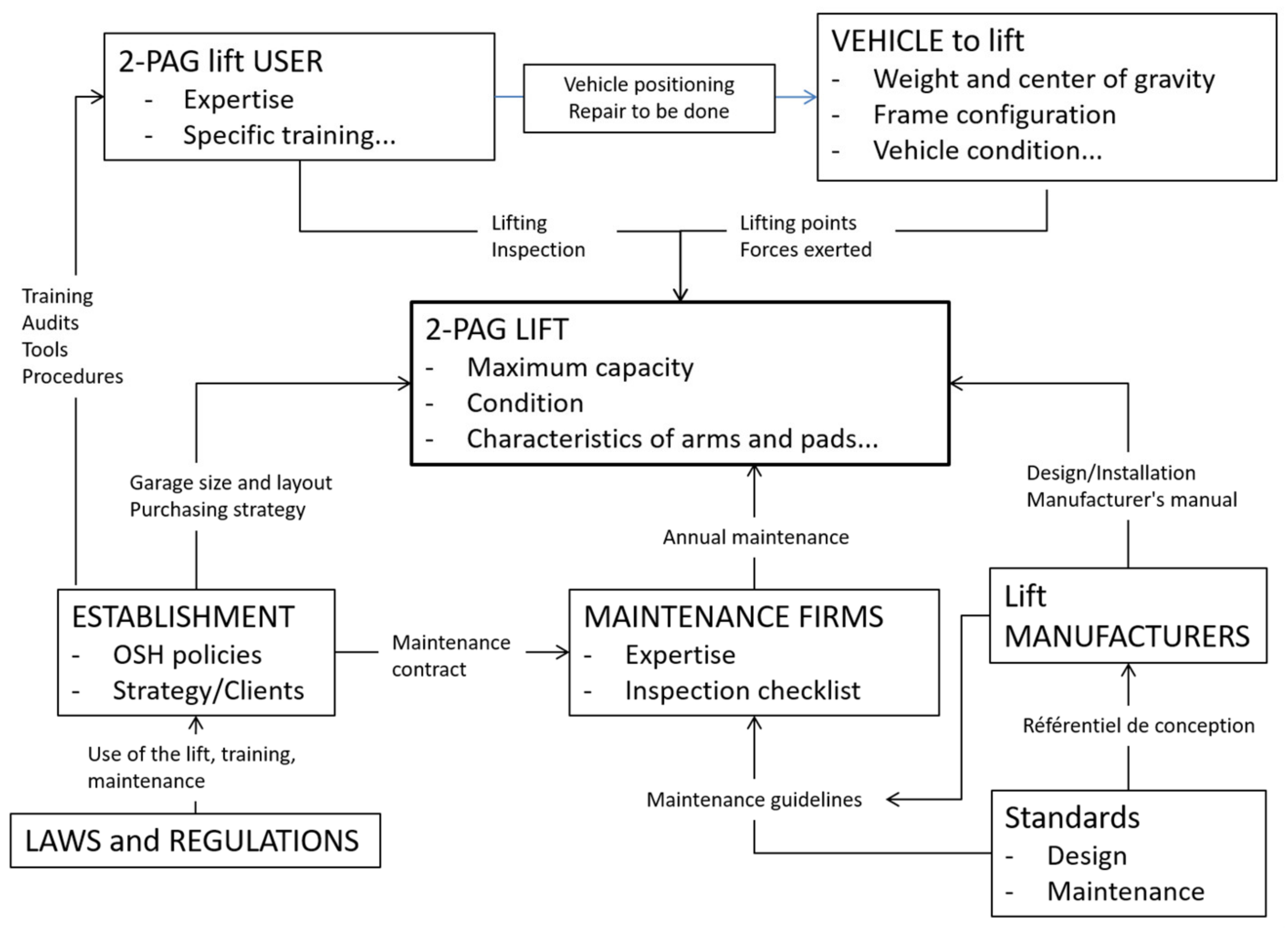
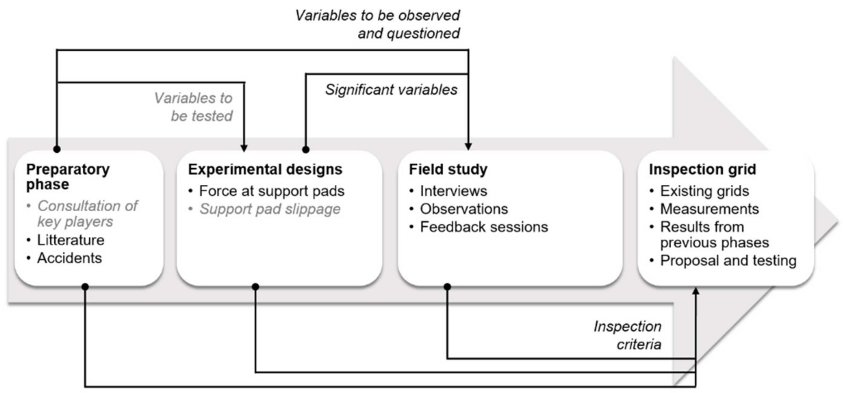
In this context, a project was set up to identify and categorize the main determinants of lifting stability with 2PAG lifts related to (1) the technical aspects and (2) the actual work activity of mechanics. A multidisciplinary research project (i.e., engineering-ergonomics) was implemented in order to answer a problem that seems to be linked to both the mechanical functioning of the equipment and its use (see Section 2.1) [3]. This paper addresses, specifically, by an experimental design, support pad slippage on a 2PAG lift as a result of external forces being exerted on a vehicle.

2. Methodology

2.1. Global Approach

The approach of the global project is summarized in Figure 3. Interviews of key players were first completed. The results obtained fed tests in a training center, in particular on the choice of controlled factors. Two experimental designs were carried out in order to have quantitative data. Forces at support pads [3] and support pads slippage as a result of external forces being exerted on a vehicle (present paper) were respectively measured according to different configurations. Finally, the data obtained will feed field observations in five garages (i.e., interviews, observations, validations in a situation of self-confrontation). A mixed methodology based on a multiple case study approach and classic tools with an ergonomic approach will be deployed at this final stage [19,20].
This paper specifically addresses the experimental design on support pad slippage as a result of external forces being exerted on a vehicle. This experimental design was based on the consultation of the key players that identifies the main issues related to the support pads.

2.2. Consultation of Key Players

A consultation of key players in the automotive sector was conducted using semi-structured interviews [21]. Convenience sampling was used as the sampling strategy for this qualitative research [22,23,24]. This involves identifying and selecting individuals or groups of individuals who have a rich knowledge base on a phenomenon of interest and who are willing to participate [24]. In this case, the participants were selected from the working group set up by the joint sector-based association (see Section 1.1). Participants selected had to have an in-depth knowledge of the sector and lifts’ operation and their function had to be varied (e.g., designer, repairer, trainer) in order to collect different points of view on the use of 2PAG lifts. In the end, seven experienced key players were interviewed: a lift installer, a lift manufacturer, two trainers in a professional center, a workers’ representative, a labor inspector and a prevention advisor. The themes addressed concerning 2PAG lifts were purchasing process, installation, training, inspection and maintenance, use and risks and possible improvements (Table 1). The interviews lasted 90 min and were carried out by two researchers. All participants took part in this research on a voluntary and non-remunerated basis. In order to inform them adequately, an information and consent form approved by an ethics committee was presented and signed before each meeting. The interviews were recorded, transcribed and then analyzed using NVivo© software. Only nodes regarding support pads and lifting points are considered here. This is the first structured contribution on this subject.

2.3. Experimental Design

2.3.1. Experimental Conditions

The testing on 2PAG lifts was conducted at a vocational training center. Asymmetrical 2PAG lifts (front arms shorter than rear arms), vehicles and a trainer were made available for the purposes of the testing. The trainer was an important player in the implementation of the experimental design, especially with a view to getting closer to the practices of the mechanics. The research team was in a logic of co-construction rather than execution. For example, the trainer helped define and validate the level of controlled factors. Among the two 2PAG lifts available at the vocational training center, the tests were carried out on the one with the largest play in the arms and support pads, in order to test a worst-case scenario.
For a better understanding of the tests, Figure 4 provides the codification of arms (A for front-left arm; B for front-right; C for rear-right; D for rear-left) and the orthonormal coordinate system used for the testing.

2.3.2. Controlled Factors

Based on the consultation of key players (Section 3.1), the chosen controlled factors in the experimental design were support pad type (adapter) (Pa), smear on support pads (S), support pad position (P), arm locking (L) and external force type (F). These five two-level factors are summarized and illustrated in Table 2. The tests were performed using one compact vehicle (weight: 1256 kg; wheel base: 2624 mm; track width: 1491 mm), with an empty trunk and with its center of gravity aligned with the lift columns. The trainer was in charge of positioning the compact vehicle and recommended lifting points were used. The tests were performed using the safest anticipated lifting configuration in order to avoid injury and vehicle damage. The tests were limited to the compact vehicle because [3] showed that the forces measured at the support pads could be very small on the rear arms. Thus, for the same applied lateral force and the same coefficient of friction between the pad and the vehicle, the expected displacement will be greater for a compact vehicle than for a heavier vehicle such as a pick-up truck (which was used in [3]). The choice of the empty trunk was made for the same reason: to limit the forces at the rear support pads as much as possible in order to maximize the measured displacement.
The number of support pad type (Pa) and external force type (F) were limited to two. This is a limitation of the study. However, some complementary tests detailed at the end of this section were carried out to fuel discussions (e.g., pick-up vehicle, loaded trunk).

Support Pad Type (Pa1, Pa2)

For the purposes of the experiment, it was important that the support pad types be different (e.g., materials, surface pattern, size, height adjustments). Thus, support pad Pa1 is square, covered with soft rubber. Rubber is described as soft because the sharp edges of lifting points C and D sink into it. Support pad Pa2 is foldable and is made out of metal. All the pads show some signs of wear like in garages. These two support pad types are often used in the training center.
These two pads have different fixing methods. It was therefore necessary to use two different, but equivalent, 2PAG lifts. An inspection of the two lifts conducted a month before the testing by an outside company did not find any irregularities.

Smear on Support Pads (S0, S1)

In order to evaluate the influence of the presence of contaminant agents, tests were conducted with support pad and lifting points of the compact vehicle cleaned with a degreaser (S0) and some other tests were conducted using support pads covered with multipurpose grease Val-Plex EP made by Valvoline (S1).

Support Pad Position (P1, P2)

Tests were conducted with the support pad axis centered under the vehicle lifting point for the four support pads (P1). Some other tests were conducted with the support pad axis off centered in the worse direction (in the extension of the arm) for the four support pads, meaning that the lifting point of the vehicle is at the edge of the support pad (P2). The orientation of the support pads with respect to the x and y axes was checked. Finally, it should be mentioned that lifting points at the front of the compact vehicle were a wide flat surface, unlike those at the back, which were a sharp edge. Sharp edges were not placed in central grooves of Pa1.

Arm Locking (L0, L1)

Configurations with the four arms locked or the four arms unlocked were tested. The unlocked position was maintained using a device tinkered for this purpose.

External Force Type (F1, F2)
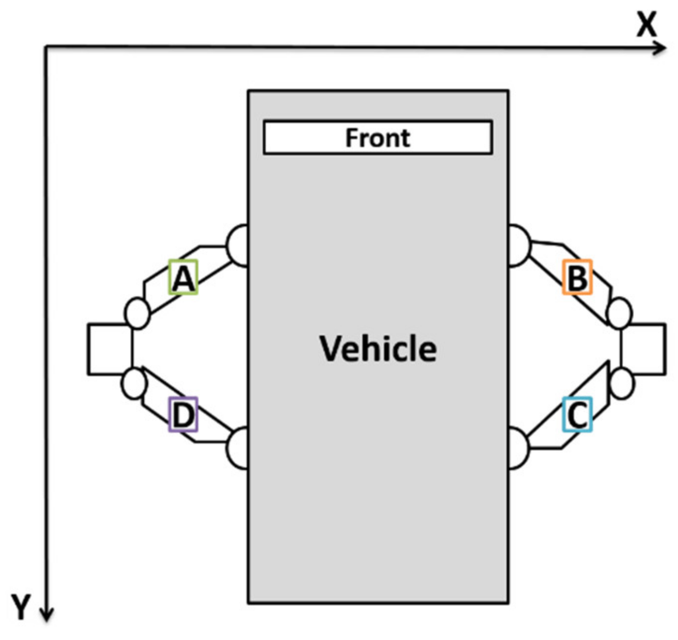
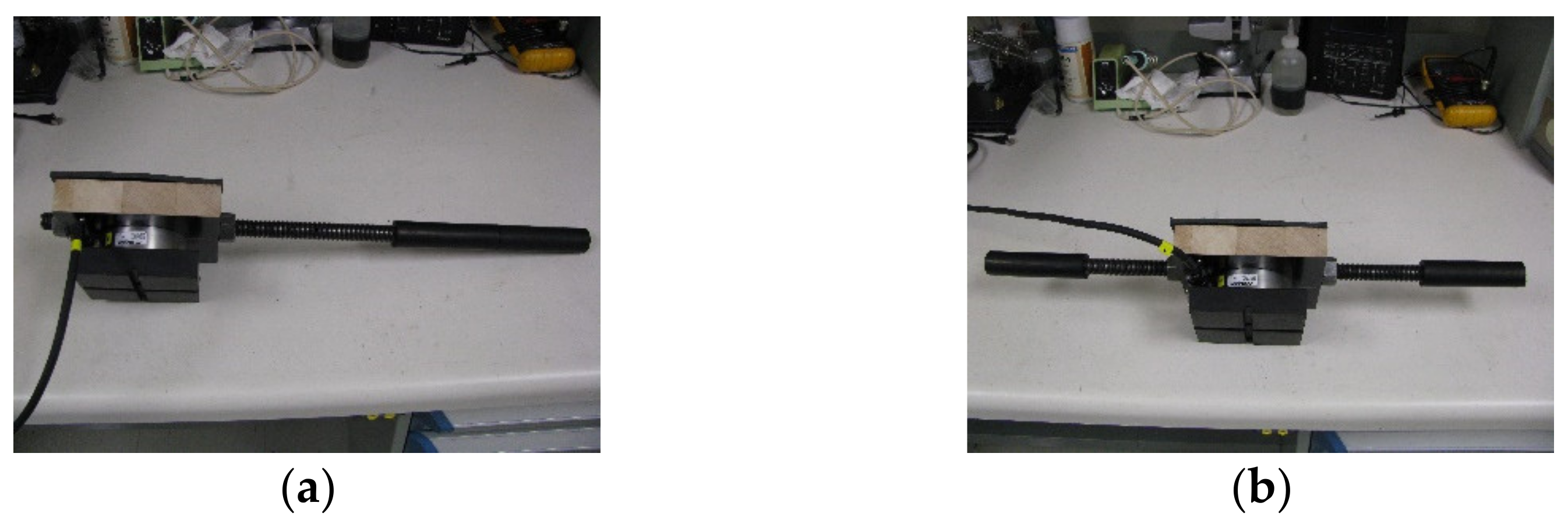
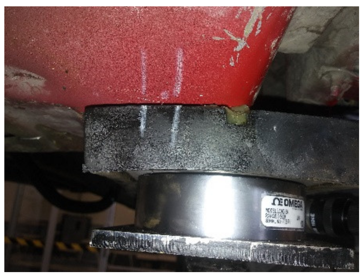
Two external force types were considered in order to represent two types of maintenance tasks performed by mechanics on vehicles. F1 (sledgehammer impacts on the rear right wheel) represents a force exerted by the mechanic to remove the rear right wheel or unstick the disk brakes (Figure 5a). F1 was only applied to one side of the vehicle; this is one of the limits of this study and it is mentioned in the Discussion section. However, based on the tests carried out in [3], there is a left–right symmetry on the vehicles. F2 (vertical force exerted by hand to the trunk) represents the force exerted by the mechanic when screwing things in the trunk (Figure 5b). These two types of forces were chosen in order to test different directions and implementations (impact, push). In order to keep some repeatability from one test to the other, F1 and F2 were defined as follows: F1—three impacts in row with a minimum impact force of 10,000 N, for a maximum of five impacts in total; F2—ten vertical pushes with a force of roughly 1000 N.

2.3.3. Measurements

Two measurements are considered for the testing: (i) support pad slippage and (ii) value of the external force applied to the vehicle in order to control this factor. Support pad slippage has been measured with a ruler after the application of the external force. To do so, several reference marks were drawn prior to the test onto the support pads and the vehicle chassis with wax pens (Figure 6). The offset between the marks after the test was measured along the x and y axes (see axes on Figure 4). The calculated slippage for a pad corresponds to x 2 + y 2 .
The external forces applied to the vehicle were measured using an Omega LCHD-5K load cell having a maximum capacity of 5000 lb (22,241 N). The cell has an accuracy of ±0.03% (i.e., ±3.0 N for a measured load of 10,000 N). The associated data acquisition system consisted of a National Instruments NI-9237 strain input module and a cDAQ-9174 chassis. An acquisition software program was developed on LabVIEW®.

2.3.4. Planning of Tests, Protocol and Statistical Analysis

The experimental design chosen was a full factorial design, i.e., all combinations of the different levels of the factors are tested. There is therefore no missing data. This corresponds to 25 tests (32): 5 factors with 2 levels each. In addition, all tests were run twice (replication). A replication of the tests allows for improved precision of the effect and a measurement of the global experimental error [25,26,27,28]. Thus, there was a total of 64 tests (32 × 2).
Support pad type (Pa) and smear (S) on support pads were considered as blocks for logistical reasons since it was time consuming to change pads between each test or to clean them. The remaining factors were randomized (i.e., performed in random order) to avoid experimental bias. Table 3 presents the order of the 64 tests performed.
Each of the tests was conducted according to the following protocol:
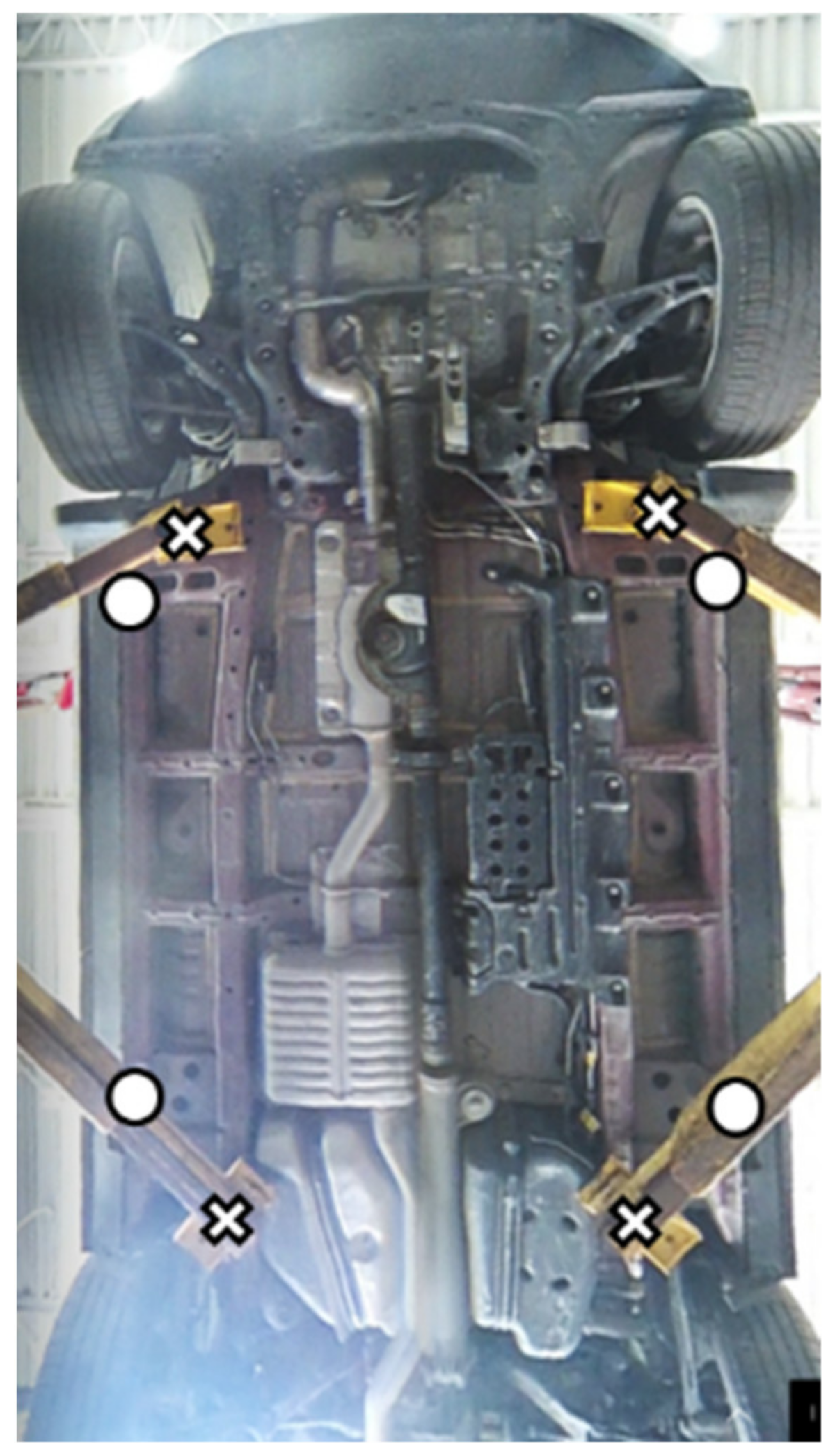
  • The vehicle was positioned properly in relation to the lift columns, respecting a previously determined mark on the ground.
  • The support pads were placed at the recommended lifting points, always in the same orientation in relation to the x and y axes.
  • The vehicle was raised to head height in order to make the marks on the support pads and the vehicle frame, and then lowered back down to approximately 20 cm from the ground for the test.
  • Forces were applied to the vehicle and recorded.
  • After checking the displacement of the support pads, the vehicle was raised to head height and secured with 4 jack stands.
  • The displacement measurements along the x and y axes were taken by a team member and compiled in a spreadsheet by another team member.
  • The jack stands were removed and the vehicle was lifted down to the ground.
The initial data analysis was conducted by taking a qualitative approach, creating graphs and charts of the various calculated indexes by configuration (i.e., total displacement of the support pad). Subsequently, analyses of variance (linear model) of the total support pad slippage were conducted using JMP® software version 14 developed by SAS to validate the model and interactions having a statistically significant influence on this measurement [25,26]. Analyses of variance were based on the following steps: (1) assessing the significance of effects with an initial model, (2) refining the model by removing insignificant effects, (3) validating the model (homogeneity, linearity, independence, and normality of residuals), and (4) interpreting and reporting the results.

2.3.5. Additional Testing

To complete the experimental design, additional tests were carried out (Table 4). Those tests determined with the trainer allowed for (i) extending the initial experimental design (e.g., support pad slippage with a different vehicle, the trunk loaded and other external forces) and (ii) exploring non-compliant work practices. The analysis of these tests was only qualitative, compensated for some limits of the experimental design and supported the discussion.

3. Results

3.1. Key Players: Support Pad and Related Issues

The consultation of key players revealed some concerns with the application of precautions related to the use of a support pad on the 2PAG lift (Table 5). Most of the discussions focused on the proper positioning of the pads on the recommended lifting points [29]. In Figure 7, the recommended lifting points at the front could not be reached (i.e., arms too long even with the telescopic extension retracted). This consultation fueled the discussion on the controlled factors to consider in the experimental design (Section 2.3.2: support pad type/smear/position, arm locking, external forces).

3.2. Experimental Design

3.2.1. Support Pad Slippage Measured

Before testing, some configurations were anticipated as critical: smeared metal support pads, unlocked arms, and lateral impact force (Pa2S1 (P1/P2)L0F1). The results show that this assumption was mostly right, as maximum slippage was measured for: Pa2S1P1L0F1 with 28.8 mm for the D pad, and Pa2S1P2L1F1 with 28.3 mm for the C pad. In general, support pad slippage was low for Pa1 (rubber pad). The maximum measured was 3 mm for the C pad (Pa1S0P2L0F2). For Pa2 (metal pad), support pad slippage was comprised between 0 and 29 mm. Mean support pad slippage were computed by controlled factor types in Table 6 for Pa1 and Table 7 for Pa2.
These means are used to compare the influence of a controlled factor. The percentage of half width of the support pad concerned was calculated to offer an order of magnitude for the slippage. Those analyses and an analysis of variance (ANOVA) are presented in the following sections

3.2.2. Statistical Analysis

A statistical analysis was conducted with JMP software to determine the factors and their interactions that have a statistically significant effect on the total support pad slippage defined as the sum of the four-support pad slippage. Initially, all the controllable factors and all the interactions of degree 2 were considered. Subsequently, those having no significant influence were eliminated (p-value > 0.05). The linear model created by JMP® software version 14 explains 83% of the variation of the index. Table 8 and Table 9 present the factors having a significant effect. The support pad type, the external force type and their interaction have the most significant influence on the total support pad slippage.
Residual analysis was performed to validate the model and check whether experimental biases had not been considered in the analysis of the experimental design. Residuals have homogeneous variance, are independent and tend to follow a normal law. Consequently, the non-controllable factors, blocks and other non-considered factors for the experimental design did not affect the validity of the testing.

4. Discussion

4.1. Controlled Factors’ Influence on the Slippage

4.1.1. Support Pad Type

Among all the controlled factors, the support pad type is the one that has the greatest influence on support pad slippage according to the ANOVA. Table 6 shows that the mean support pad slippage is less than 1 mm for Pa1 (rubber pad), whilst Table 7 shows that support pad slippage for Pa2 (metal pad) is, respectively, 1.6, 2.1, 8.6 and 7.4 mm for pads A, B, C and D. Furthermore, slippage was observed for 56% (18/32) of tests conducted with Pa1 and 91% (29/32) of tests conducted with Pa2. Maximum displacement with Pa1 is only 3 mm for configuration Pa1S0P2L0F2, which is 5% of the half width of the pad (59 mm). For Pa2, the maximum displacement is 29 mm for configuration Pa2S1P1L0F1, which is 53% of the half width of the pad (55 mm).
The significantly smaller slippages observed for Pa1 are partly explained by the rubber/steel coefficient of friction (COF), which is higher that the steel/steel COF. The geometry of the contact can also have an influence depending on the surface hardness of the pad covering. The lifting points of the compact vehicle for C and D pads dug a little into the rubber for Pa1, which helped maintain the support pad in position for these two arms. Indeed, the slippage for the front pads (A and B), where the lifting points are a flat surface, is slightly higher.
For Pa1 and the two types of force, the authors observed some movement of the extension of lift arms, which extended or shortened a little (without impairing the vehicle stability), contrary to Pa2, where slippage occurred at the support pad interface, especially for C and D pads, which are at the axle where the force was exerted.
Overall, the tests carried out tend to show that in a given situation (e.g., determined vehicle and lifting points) the type of support pad has a very great influence on the support pad slippage. In the experiment, the support pad with a rubber cover (Pa1) performed much better regarding slippage. However, this is not enough to conclude generally that one support pad type is better than another.

4.1.2. Smear on Support Pads

Based on Table 6, smear on support pads had no significant influence on slippage for rubber pad Pa1. Smear has a bigger influence for Pa2 (metal pad), especially for the rear pads, where the external force is applied. The increase in slippage for these support pads was roughly multiplied by two when they were smeared, with +4 mm for support pad C and +5 mm for support pad D (Table 7).

4.1.3. Support Pad Position

According to the ANOVA, off centering the support pad had no significant influence on the support pad slippage: less than 1 mm difference between P1 (centered) and P2 (off-centered) for Pa1 (Table 6) and generally a slight decrease in support pad slippage for Pa2 (Table 7). Thus, flexion in the support pad structure and the resulting inclination of the support surface do not generate more slippage than the centered position in the experiment. However, from a practical point of view, the off-centered position remains a risky position since it leaves less room in case of an unexpected slippage (e.g., external forces). This position also generates greater stresses in the support pad (i.e., premature wear, breakage). The initial placement of the support pad is a major safety measure as support pad slippage went up to 53% of the pad half-width during the tests.

4.1.4. Arm Locking

According to the ANOVA, arm locking had no significant influence on the support pad slippage: 56% (10/18) of the tests where slippage occurred were made with arms locked for Pa1 and 52% (15/29) for Pa2. Even if the arm locking system is active, some slight movement of the arm is still possible. It could explain why this controlled factor is not significant. The angle of arm movement possible varied between 6° and 9° according to the measurements.

4.1.5. Type of Force

According to the ANOVA, external force type had a significant influence on the support pad slippage, especially for Pa2. Table 7 shows that mean slippage is greater for F1 (lateral impacts) than for F2 (vertical pushes) for the four pads. The mean difference for rear pads is 12.5 mm. Compared to the half-width of Pa2, the slippage goes from 4.5% (F2) to 26.8% (F1) for pad C, and from 1.9% (F2) to 24.8% (F1) for pad D. There is also an increase in support pad slippage for front pads: from 0.8 (F2) to 2.2 mm (F1). There is no general tendency observed for Pa1 (Table 6).

4.1.6. Additional Testing

Between two jobs on the same vehicle, mechanics sometimes lift down the vehicle but keep the support pads in contact with the vehicle. However, this contact could be lost if the lift went too low. Thus, some additional tests were carried out to study the support pad displacement in this case. The configurations tested included (Pa1/Pa2)S0P1 (L0/L1) with replica for the compact vehicle and Pa2S0P1L0 with a loaded pick-up. At first, the authors anticipated that the arm locking system would help maintain the support pad in place. Following testing, it appears that neither arm locking nor support pad type (and lift type) had a significant influence on the support pad displacement, contrary to the vehicle type. Table 10 shows a significant difference between V1 (compact car) and V2 (pick-up truck).
This major difference could be explained by the play in the gearbox of the vehicle. Even with the vehicle in parking mode, without the use of the handbrake, the car can move slightly forward or backward when the wheels touch ground again. The gearbox play is higher for V2 than for V1. As there is play in the arms, these are driven by the movement of the vehicle until there is no more contact. Considering the results, mechanics should be aware that this situation is potentially dangerous, especially for pick-up trucks, as a 30 mm displacement may be sufficient to lose the link between the pad and the lifting point. In the testing, V2 had to be moved backwards after every two tests in order to keep placing the support pads correctly.
During the additional testing with V2 and F2 (vertical force), a loss of contact was observed between the front pads and the lifting points, as the center of mass of V2 is closer to the rear pads (especially with loaded trunk). This contact loss did not generate significant support pad displacement. However, it could lead to support pad displacement if some stress was applied on the free lift arm.

4.2. A Multifactorial Problem

These results, combined with those on force distribution at the pads, show that a vehicle falling off a 2PAG lift is a multifactorial problem [3]. A combination of circumstances seems necessary. In a controlled environment, it was not so easy to get the compact vehicle off the pads (unless it was lifted manually). Recent investigation reports and scientific literature related to 2PAG lifts mainly discuss the integrity and involvement of the arm locking system [4,17,18]. Without questioning the conclusions of these documents and the importance of this safety component, the experimental results show that a defective arm locking system may not be a sufficient cause to explain accidents alone. An arm locking system failure does not explain the initiation of vehicle or arm movement.
According to the experimental results presented herein and in [3], the initiation of arm movement for those fatal accidents could be explained by a slip off of the vehicle from the support pad, caused by one or a combination of those elements:
  • Lifting point of the vehicle positioned on the edge of the support pad: This situation causes two phenomenons: (a) A slight slippage of the support pad can induce the fall of the vehicle, especially for pads without stops. There is no safety margin, as slippages were measured during the tests in many configurations (up to 53% of the pad half-width). (b) It maximizes the play in the cantilevered support pad and causes the pad to be inclined, thus inducing horizontal forces.
  • Support pad type and external forces: support pad type and external force type are the ones that have the greatest influence on support pad slippage according to the ANOVA. However, more data are needed on support pad and the match with lifting points in real conditions.
  • Support pad with very little or no charge: a lift arm with almost no charge is more easily moveable, especially if some play exists in the lift arm locking system [3]. Hence, the question relative to the arm locking system is not only a question of maximum force and resistance, but also a question of allowable play when the arm is locked. According to Woody and MacDonald [18], the design of some arm locking systems should be retrofitted.

4.3. Experimental Limitations

This research work is the first to study the use of 2PAG lifts in such a specific way [3]. In this context, the chosen methodological approach was mainly exploratory, which is a methodological limitation. This resulted in the testing of more variables at the expense of more levels (e.g., number of support pad types) or more replications. Based on the results, an experimental design centered on the support pad type (cover) and type of forces (direction and location) seems necessary and relevant. Less significant variables (e.g., arm lock, support pad position, dirt) could be left out. Another limitation of the study is that these findings were obtained in a controlled environment compared to the variability of situations in garages. These results are therefore a first step to target the factors to be explored in real situations concerning the stability of vehicles during lifting (i.e., slippage of support pad, distribution of forces in the four arms). These data will therefore feed forthcoming field observations in garages.

5. Conclusions

Based on the analysis of variance and interpretation of the results, the factors that had a significant influence on the support pad slippage were (i) support pad type, (ii) external force type and (iii) the interaction between those two controlled factors. Smear on support pads can increase the slippage for steel pads, but its influence is less significant than the three factors listed before. Arm locking and support pad position were not statistically significant. The type of contact between the support pad and the compact vehicle lifting point seems significant for Pa1 (rubber pad). Indeed, a flat lifting point is more prone to slippage than the thin edge deforming the rubber. Finally, the maximum slippage (29 mm) was measured for tests with steel pads, smeared with grease and with lateral impact forces (Pa2S1F1). From a practical standpoint, the following observations and results should be considered:
  • The initial placement of the support pad is a major safety measure, as support pad slippage can go up to 53% of the pad half-width. Moreover, many test configurations led to support pad slippage. A bad initial pad placement (pad edge) could lead to a contact loss between the vehicle and support pad, and ultimately a fall of the vehicle.
  • Support pad slippage is much lower for the soft rubber pads. This coating gives better results than their steel counterparts in these experimental conditions (i.e., type of vehicle and configuration of the lifting points).
  • The external force type has a significant impact on the slippage: lateral impacts imparted with a sledgehammer generated greater displacements than vertical pushes in the trunk.
  • Finally, lifting the vehicle down to the ground and lifting it again without readjusting the position of the support pads when the contact was lost is potentially dangerous, as it caused displacements of up to 32 mm in the testing with the pick-up truck. This is already a non-recommended practice, but it can happen sometimes inadvertently.
These results should challenge lift manufacturers to propose support pad designs that would reduce this inherent risk of the 2PAG lifts. Providing support pads with high-friction rubber covering and stops/edges with the newest lifts instead of the traditional folding metal support pads seems like a step in the right direction. Support pads (and arms) that are more versatile in their adjustments (e.g., continuous height adjustment, a variety of extensions, exchangeable/removable pad as needed) will also promote proper support pad placement on recommended lift points. Vehicle manufacturers could also participate in managing this risk at the source [30] through the design of their lift points. This should be particularly the case with the electric vehicles under development with the increasingly large presence of batteries under these vehicles. Garages do not have control over the design of vehicles, but they do have control over the selection and installation of 2PAG lifts in their workshop. To do this, a purchasing process must be put in place that includes criteria related to the safety of mechanics. This purchasing process should be based on (1) the mobilization of the garage’s experienced mechanics to establish the most important criteria, (2) statistical data on the types of vehicles lifted in the garage and (3) the testing of different options and the visit of reference garages. In addition, investing in a quality lift and a range of support pad adapters will be beneficial when considering the big picture (e.g., safety, lift maintenance, versatility).

Author Contributions

Conceptualization, D.B.-V.; B.G.; S.B.; M.G. and É.L.; methodology, D.B.-V.; B.G.; S.B.; M.G. and É.L.; data collection, D.B.-V.; B.G.; K.C.B.; S.B.; M.G. and É.L.; formal analysis, D.B.-V.; B.G.; K.C.B.; S.B. and M.G.; writing—original draft preparation, D.B.-V. and B.G.; writing—review and editing, D.B.-V.; B.G.; K.C.B.; S.B.; M.G. and É.L. All authors have read and agreed to the published version of the manuscript.

Funding

This research was funded by the Institut de recherche Robert-Sauvé en santé et en sécurité du travail (IRSST), grant number 2018-0002.

Institutional Review Board Statement

The study was approved by the Ethics Committee of the Institut de recherche Robert-Sauvé en santé et en sécurité du travail (IRSST) (# 2018-0002, 25 May 2019).

Informed Consent Statement

Informed consent was obtained from all subjects involved in the study.

Data Availability Statement

Not applicable.

Acknowledgments

The authors wish to thank the professional training center and the trainer that agreed to participate in this study.

Conflicts of Interest

The authors declare no conflict of interest. The funders had no role in the design of the study; in the collection, analyses, or interpretation of data; in the writing of the manuscript, or in the decision to publish the results.

References

  1. Société de l’Assurance Automobile du Québec (SAAQ). Nombre de Véhicules en Circulation Selon Le Type D’utilisation, Le Type de Véhicule Et L’âge Du Véhicule, Québec Et Régions Administratives [Number of Vehicles in Circulation by Type of Use, Type of Vehicle and Age of Vehicle, Québec and Administrative Regions]; Gouvernement du Québec: Quebec, QC, Canada, 2021. [Google Scholar]
  2. American National Standard Institute (ANSI); Automotive Lift Institute (ALI). Standard for Automotive Lifts—Safety Requirements for Operation, Inspection and Maintenance (ALOIM); ALI: Cortland, NY, USA, 2008. [Google Scholar]
  3. Burlet-Vienney, D.; Galy, B.; Kusson Bertrand, K. Analysis of Vehicle Stability When Using Two-Post Above-Ground Automotive Lifts: Distribution of Forces in Arms. Saf. Sci. 2021, 134, 105042. [Google Scholar] [CrossRef]
  4. Centre de Documentation. Available online: https://www.centredoc.cnesst.gouv.qc.ca/in/fr (accessed on 20 January 2022).
  5. American National Standard Institute (ANSI); Automotive Lift Institute (ALI). Standard for Automotive Lifts—Safety Requirements for Installation and Service (ALIS); ALI: Cortland, NY, USA, 2009. [Google Scholar]
  6. American National Standard Institute (ANSI); Automotive Lift Institute (ALI). Standard for Automotive Lifts—Safety Requirements for Construction, Testing and Validation (ALCTV); ALI: Cortland, NY, USA, 2017. [Google Scholar]
  7. BS EN 1493:2010; Vehicle Lifts. British Standards Institution (BSI): London, UK, 2010.
  8. BS 7980:2013+A1:2012; Vehicle Lifts—Installation, Maintenance, Thorough Examination and Safe Use—Code of Practice. British Standards Institution (BSI): London, UK, 2014.
  9. AS/NZS 2550.9:1996; Standards Australia and Standards New Zealand (Standards AS/NZ). Cranes—Safe Use. Part 9: Vehicle Hoists. Standards Australia: Homebush, Australia, 1996.
  10. AS/NZS 1418.9:1996; Standards Australia, Standards New Zealand (Standards AS/NZ). Cranes (Including Hoists and Winches) Part 9: Vehicle Hoists. Standards Australia: Homebush, Australia, 1996.
  11. Auto Prévention. Le Travail Sous Le Véhicule. In Le Levage De Véhicules Sur Pont Élévateur À Deux Colonnes [Work under the Vehicle. Vehicle Lifting with Two-Post above Ground Lift]; Auto Prévention: Brossard, QC, Canada, 2014. [Google Scholar]
  12. Auto Prévention. L’entretien Préventif Des Ponts Élévateurs [Preventive Maintenance of Automotive Lifts]; Auto Prévention: Brossard, QC, Canada, 2019. [Google Scholar]
  13. Heath, R. Don’t Be an Accident Statistic—Lift It Right; ALI: Cortland, NY, USA, 2013. [Google Scholar]
  14. Valladeau, A.S.; Lupin, H. Réparation Et Entretien Des Véhicules Automobiles Légers (ED6282) [Repair and Maintenance of Light Motor Vehicles]; INRS: Paris, France, 2017. [Google Scholar]
  15. Eberhard, J.; Green, P. The Development and Testing of Warnings for Automotive Lifts; The University of Michigan Transportation Research Institute: Ann Arbor, MI, USA, 1989. [Google Scholar]
  16. Williams, M.; Green, P.; Paelke, G. Further Development of Warnings for Automotive Lifts; The University of Michigan Transportation Research Institute: Ann Arbor, MI, USA, 1991. [Google Scholar]
  17. Barnett, R.L.; Glauber, J.B. Automotive Lifts—Unrestrained vs. Restrained Swing Arms. Saf. Brief 2009, 29, 373–387. [Google Scholar]
  18. Woody, P.; McDonald, A. Assessment of the Arm Locking Systems of Two-Post Vehicle Lifts (RR1030); Health and Safety Laboratory: Buxton, UK, 2015. [Google Scholar]
  19. Yin, R.K. Case Study Research: Design and Methods, 4th ed.; SAGE Publications: Thousand Oaks, CA, USA, 2009. [Google Scholar]
  20. St-Vincent, M.; Vézina, N.; Bellemare, M.; Denis, D.; Ledoux, É.; Imbeau, D. L’intervention En Ergonomie [The Intervention in Ergonomics]; IRSST/Éditions Multi Mondes: Montreal, QC, Canada, 2011. [Google Scholar]
  21. Theureau, J. Le Cours D’action: Analyse Sémio-Logique [The Course of Action: Semio-Logical Analysis]; Peter Lang: Berne, Switzerland, 1992. [Google Scholar]
  22. Bricki, N.; Green, J. A Guide to Using Qualitative Research Methodology; London School of Hygiene and Tropical Medicine: London, UK, 2007. [Google Scholar]
  23. Patton, M.Q. Qualitative Research. In Encyclopedia of Statistics in Behavioral Science; Everitt, B.S., Howell, D.C., Eds.; Wiley: Hoboken, NJ, USA, 2005. [Google Scholar]
  24. Palinkas, L.A.; Horwitz, S.M.; Green, C.A.; Wisdom, J.P.; Duan, N.; Hoagwood, K. Purposeful sampling for qualitative data collection and analysis in mixed method implementation research. Adm. Policy Ment. Health 2015, 42, 533–544. [Google Scholar] [CrossRef] [PubMed] [Green Version]
  25. Carignan, M. Optimiser La Performance Par La Planification D’expériences (DOE) [Optimizing Performance by Experimental Plans]; ÉTS Formation/Différence: Montreal, QC, Canada, 2018. [Google Scholar]
  26. Dagnelie, P. Principes D’expérimentation: Planification des Expériences et Analyse de Leurs Résultats [Experimental principles: Planning of Experiments and Analysis of Their Results]; Presses Agronomiques: Gembloux, France, 2012. [Google Scholar]
  27. Linder, R. Les Plans D’expériences, Un Outil Indispensable À L’expérimentateur [Experimental Plans, an Essential Tool for the Experimenter]; Presses de l’École Nationale des Ponts et Chaussées: Paris, France, 2005. [Google Scholar]
  28. Alexis, J.; Alexis, P. Pratique industrielle des plans d’expériences. In La Qualité À Moindre Coût: La Méthode Tagushi [Industrial Practice of Experimental Plans. Quality at a Lower Cost: The Tagushi Method]; AFNOR: Paris, France, 1999. [Google Scholar]
  29. Automotive Lift Institute (ALI). Vehicle Lifting Points for Frame Engaging Lifts; Model Years (1995–2019); ALI: Cortland, NY, USA, 2019. [Google Scholar]
  30. Kletz, T.A. Inherently safer design—Its scope and future. Process Saf. Environ. Prot. 2003, 81, 401–405. [Google Scholar] [CrossRef]
Figure 1. Vehicle raised using a 2-post above-ground automotive (2PAG) lift.
Safety 08 00058 g001
Figure 2. Context and stakeholders related to the use of 2PAG lifts.
Safety 08 00058 g002
Figure 3. Overall methodology (parts discussed in this paper are in gray and italic).
Safety 08 00058 g003
Figure 4. Identification of lift arms and orthonormal coordinate system used for testing.
Safety 08 00058 g004
Figure 5. (a) Load cell assembly for lateral force applied to the rear wheel. (b) Load cell assembly for vertical force applied to the trunk.
Safety 08 00058 g005
Figure 6. Reference lines on the support pad and the chassis before the test, along the x axis.
Safety 08 00058 g006
Figure 7. Difference between the lifting points used (crosses) and those recommended by the manufacturer (circles) due to the characteristics of the lift (arm length).
Safety 08 00058 g007
Table 1. Themes covered during interviews with key players in the automotive sector.
ThemesExamples of Information Collected
Automotive lift marketLift models available on the market (brands, types, construction standards, new vs. used products), most popular, advantages, buyers and users, responsibilities and obligations of manufacturers and suppliers
Buying processFormulation of requests/needs by the buying garages (visit of suppliers), variables to define the needs and characteristics of the lift (capacity, space, type of work to be confucted on the vehicle), place of occupational health and safety for the buyers, examples of specifications, guarantees offered
Implementation in garages
Training and information on the use of lifts
Modalities/procedures for the installation of lifts in the garages, physical and organizational implementation plan developed by the buyers (people authorized to use it, lifts dedicated to a type of task)
Training provided: when (hiring, purchase of a new lift, refurbishment), who (training center, supplier, fellow mechanic) and to whom, contents/methods (duration, theory/practice), information documents given to owners of new lifts
UseAre recommendations/specifications for lift use followed? Main risks, consideration of risks for users, challenges/difficulties in using lifts (vehicle model, type of tasks to be conducted, user experience)
Vehicle fallsDescription of vehicle falls, circumstances, contributing factors to falls, means of assessing vehicle stability, resources for assessing stability and risk
Inspection and maintenanceDaily and periodic inspections/maintenance, criteria/tools provided (inspection/maintenance guide), skills required (responsibility mechanic, owner, specialized technician, engineer), condition of lifts in garages, main problems/interventions/exemptions related to lift maintenance or repair, lift life span
Reducing the risks associated with falling vehiclesExisting technical or organizational means to limit risks, available resources (experts, organizations, information), solutions to reduce risks (developments, necessary interventions)
Table 2. Controlled factors in the experimental design.
Controlled FactorsLevel/CodeDescriptionIllustrations
Support pad type
(Pa)
Pa1: RubberSquare support pad with soft rubber cover Safety 08 00058 i001
Pa1
Safety 08 00058 i002
Pa2
Pa2: MetalFoldable steel support pad
Support pad smear
(S)
S0: CleanSupport pads and lifting points cleaned Safety 08 00058 i003
S1
S1: SmearedSupport pads covered with multipurpose grease
Support pad position
(P)
P1: CenteredLifting point centered on the support pad Safety 08 00058 i004
P1
Safety 08 00058 i005
P2
P2: Off centeredLifting point off centered on the support pad
Arm locking
(L)
L0: Unlocked4 locking devices not used Safety 08 00058 i006
L0
Safety 08 00058 i007
L1
L1: Locked4 locking devices in use
External force type
(F)
F1: Lateral impactSledgehammer impacts on the rear right wheel Safety 08 00058 i008
F1
Safety 08 00058 i009
F2
F2: Vertical forceVertical forces exerted by hand to the trunk
Table 3. Planning of tests for Pa1 and Pa2.
Support Pad Type (Pa)
Pa1 (Rubber); Pa2 (Metal)
Support Pad Smear (S)
S0 (Clean); S1 (Smeared)
Support Pad Position (P)
P1 (Centered); P2 (Off Centered)
Arm Locking (L)
L0 (Unlocked); L1 (Locked)
External Force Type (F)
F1 (lateral); F2 (Vertical)
Pa1S0P1L1-F2; L0-F2; L0-F1; L1-F1Original
Pa1S0P2L1-F1; L0-F1; L0-F2; L1-F2
Pa1S1P1L1-F2; L0-F2; L0-F1; L1-F1
Pa1S1P2L1-F1; L0-F1; L0-F2; L1-F2
Pa1S1P1L1-F2; L0-F2; L0-F1; L1-F1Replicate
Pa1S1P2L1-F1; L0-F1; L0-F2; L1-F2
Pa1S0P1L1-F2; L0-F2; L0-F1; L1-F1
Pa1S0P2L1-F1; L0-F1; L0-F2; L1-F2
Pa2S0P1L1-F2; L0-F2; L0-F1; L1-F1Original
Pa2S0P2L1-F1; L0-F1; L0-F2; L1-F2
Pa2S1P1L1-F2; L0-F2; L0-F1; L1-F1
Pa2S1P2L1-F1; L0-F1; L0-F2; L1-F2
Pa2S1P1L1-F2; L0-F2; L0-F1; L1-F1Replicate
Pa2S1P2L1-F1; L0-F1; L0-F2; L1-F2
Pa2S0P1L1-F2; L0-F2; L0-F1; L1-F1
Pa2S0P2L1-F1; L0-F1; L0-F2; L1-F2
Table 4. Description of additional testing.
ThematicTest
Other support pad slippage testsSupport pad slippage: compact vehicle, trunk loaded (216 kg). Tested configurations: Pa2S0P1L0F1 and Pa2S0P2L0F2
Support pad slippage: pick-up (weight: 2436 kg; wheel base: 3531 mm; track width: 1700 mm) and Pa2 (metal). Tested configurations: Pa2S0P1L0(F1/F2) with and without load in the trunk (216 kg).
Support pad slippage: front/rear external force type on the pick-up, Pa2 support pads folded in the same way and locked arms. Tested configuration: Pa2S0P1L1
Non-compliant work practiceSupport pad displacement following the lifting down of the vehicle to the ground (support pads not in contact with the lifting points anymore) and lift off of the vehicle without readjusting the support pad position. Tested configurations with replicas:
-
Compact vehicle: (Pa1/Pa2)S0P1(L0/L1)
-
Pickup: Pa2S0P1L0 with the pick-up loaded
Table 5. Concerns reported by key players on the use of support pad on 2PAG lift regarding safety instructions.
ConcernsExplanation
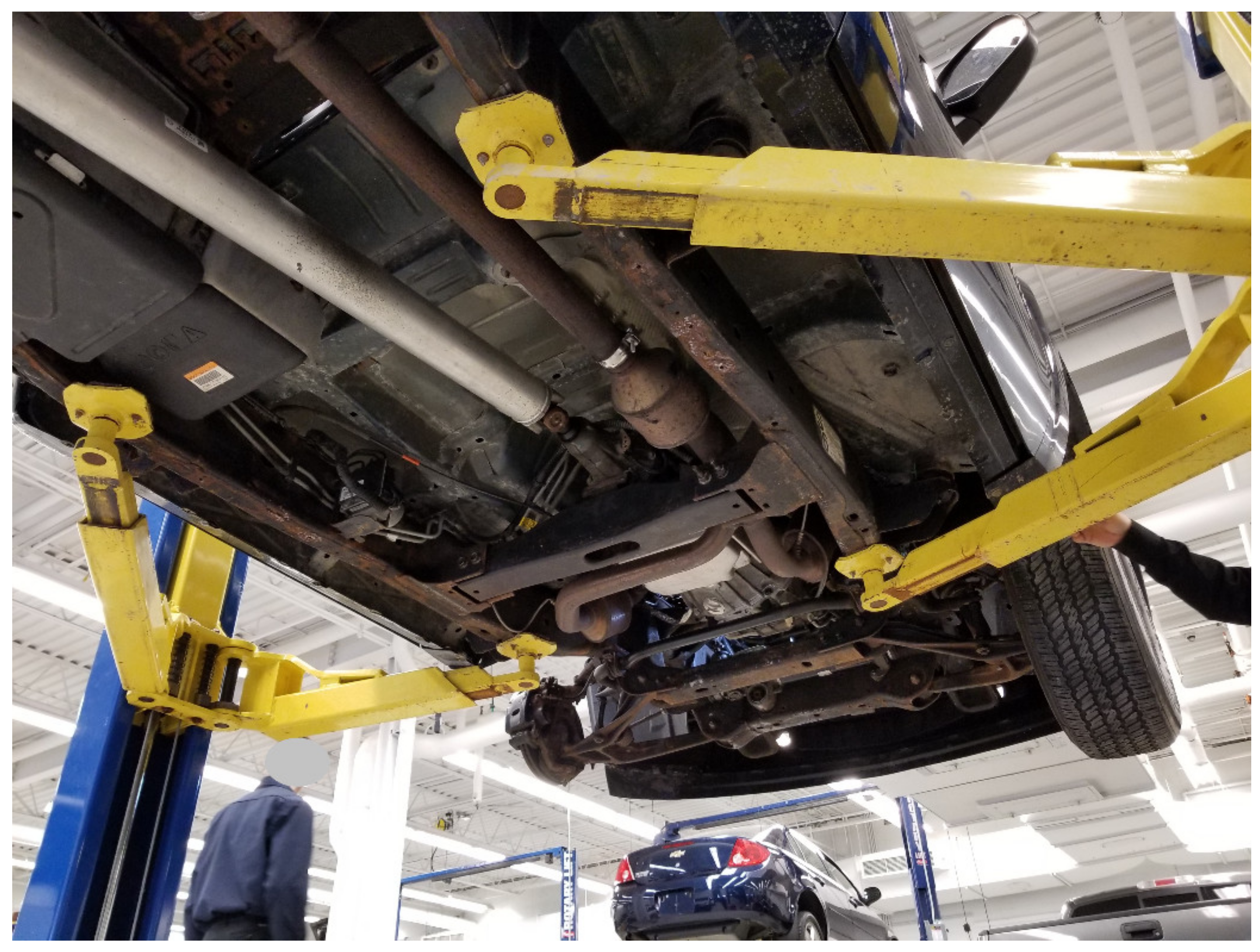
Compliance with recommended lifting pointsMechanics may have difficulties to reach the lifting point recommended by the manufacturer because of (i) the physical limits of the lifts (e.g., out of reach with telescopic arms) (Figure 7), (ii) the vehicle specifications (e.g., space between the ground and frame of the vehicle, plastic parts, damaged lifting points, rust), and (iii) the mismatch between the type of pads available and the characteristics of the lifting point (e.g., foldable steel support pads only offer three heights).
Support pad suitabilityThere is a great variability of vehicles (e.g., size, characteristics of lifting points) and support pads (e.g., materials, surface pattern, size, height adjustments and clearances) (Table 2).
Each support pad has its own specifications and mechanical behavior. A support pad type is sometimes not the most suitable for a situation (e.g., pad with stops and a large flat lifting point). It is sometimes difficult to have the best “support pad-lifting point” match and it is not always possible to change the type of support pad on a lift.
Support pad positionningSupport pads should be positioned with the pad axis centered with the lifting point of the vehicle (Table 2). This type of positioning requires the mechanic to bend under the vehicle and to thoroughly adjust the support pad position. Some key players are concerned about the fact that this adjustment is not conducted properly each time (e.g., because of knee pain, lack of time, poor housekeeping/snow, by habits). Moreover, the height of the pad is not always adjusted, which can cause a pad to not support as much weight as it should.
Contaminant agentsThe presence of contaminant agents on the support pads or lifting points of the vehicle was mentioned as a risk factor during consultation (Table 2).
Arm locking systemDuring lifting of the vehicle, arm locking systems must be active. However, these devices demand a careful maintenance to be fully functional. Mechanics should verify that the arms are locked during lifting. Some key players expressed their concerns on this point.
Work on vehiclesWhen working on vehicles, mechanics can apply significant forces with tools to remove mechanical parts. These forces exerted (e.g., changing tires) can generate vehicle movement. Other more complex work such as removing the transmission or the engine can change the position of the vehicle’s CG.
Table 6. Square support pad with rubber cover (Pa1)—Mean support pad slippage for different controlled factors.
Controlled FactorPad A (mm)% of Half-Width APad B (mm)% of Half-Width BPad C (mm)% of Half-Width CPad D (mm)% of Half-Width D
F1 (lateral)0.30.4%0.50.8%0.10.2%0.00.0%
F2 (vertical)0.61.0%0.30.5%0.30.5%0.00.0%
L0 (unlocked)0.40.7%0.40.7%0.30.6%0.00.0%
L1 (locked)0.40.7%0.30.5%0.10.1%0.00.0%
P1 (centered)0.30.6%0.10.2%0.10.2%0.00.0%
P2 (off-centered)0.50.8%0.61.1%0.30.5%0.00.0%
S0 (clean)0.61.0%0.30.5%0.30.5%0.00.0%
S1 (smear)0.30.4%0.40.7%0.10.2%0.00.0%
Average0.40.7%0.40.6%0.20.3%0.00.0%
Table 7. Foldable steel support pad (Pa2)—Mean support pad slippage for different controlled factors.
Controlled FactorPad A (mm)% of Half-Width APad B (mm)% of Half-Width BPad C (mm)% of Half-Width CPad D (mm)% of Half-Width D
F1 (lateral)2.03.6%3.25.9%14.726.8%13.624.8%
F2 (vertical)1.22.1%1.01.8%2.54.5%1.11.9%
L0 (unlocked)1.93.4%2.74.9%9.317.0%7.713.9%
L1 (locked)1.32.3%1.52.8%7.814.3%7.012.8%
P1 (centered)1.01.8%2.34.2%9.417.1%9.617.4%
P2 (off-centered)2.13.9%1.93.5%7.814.1%5.19.3%
S0 (clean)1.42.6%2.24.1%6.612.0%4.78.6%
S1 (smear)1.73.1%2.03.6%10.619.2%10.018.1%
Average1.62.9%2.13.8%8.615.6%7.413.4%
Table 8. ANOVA for total support pad slippage.
SourceDegree of FreedomSum of the SquaresMean SquareF-Value
Model713,637.1351948.1645.9785
Error562372.78442.37Prob. > F
Corrected total6316,009.919 <0.001
Table 9. Factors and interactions having a statistically significant influence on total support pad slippage.
SourceSum of the SquaresF-ValueProb. > F
Support pad Pa5566.60131.380.00000
Support pad Pa × External force F3172.9874.890.00000
External force F3058.2472.180.00000
Smear S × External force F728.6117.200.00012
Support pad position P × External force F432.5910.210.00230
Support pad Pa × Smear S365.358.620.00481
Smear S312.757.380.00875
Table 10. Factors and interactions having a statistically significant influence on total support pad slippage.
Mean Slippage (mm)Pad APad BPad CPad D
V1S0P1 (compact)Pa1 (rubber)2212
Pa2 (metal)1220
L0 (unlocked)1321
L1 (locked)2211
V2Pa2S0P1L0 (pick-up)16161923
Publisher’s Note: MDPI stays neutral with regard to jurisdictional claims in published maps and institutional affiliations.

