Article

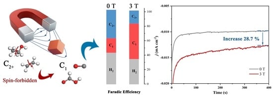
A Strong Magnetic Field Alters the Activity and Selectivity of the CO2RR by Restraining C–C Coupling

1
Hefei National Research Center for Physical Sciences at the Microscale and Department of Materials Science & Engineering, University of Science and Technology of China, Hefei 230026, China
2
The High Magnetic Field Laboratory, Hefei Institutes of Physical Science, Chinese Academy of Sciences, Hefei 230031, China
*
Authors to whom correspondence should be addressed.
Magnetochemistry 2023, 9(3), 65; https://doi.org/10.3390/magnetochemistry9030065
Submission received: 29 January 2023 / Revised: 18 February 2023 / Accepted: 23 February 2023 / Published: 26 February 2023
(This article belongs to the Special Issue Study on the Growth and Performance of Materials under Magnetic Field)

Abstract

:
As an external field, a magnetic field can change the electrocatalytic activity of catalysts through various effects. Among them, electron spin polarization on the catalyst surface has attracted much attention. Herein, we investigate the sensitive response behavior of a Cu2O nanocubes to an in situ magnetic field. Under a 3 T strong magnetic field, the total transferred electron quantity in IT test (−1.1 VRHE) and the current density in the polarization curve increase by 28.7% and 54.7%, respectively, while the onset potential decreases significantly by 114 mV. Moreover, it was found that product selectivity was also altered by the magnetic field. The Faraday efficiency of C1 increases substantially, along with the inhibition of C2+ reaction paths and the HER. Our experimental results and DFT calculation demonstrate that a hybrid magnetic effect accelerates the CO2RR kinetic and generates spin polarization of the catalyst surface. The polarized surface changes the binding energy of *OCHO/*COOH and inhibits singlet C–C coupling, which restrains the C2+ reduction path and thus more CO2 is reduced to HCOOH.

Graphical Abstract

1. Introduction

The CO2 reduction reaction (CO2RR) is able to capture the carbon dioxide in the atmosphere and transform it into diversified hydrocarbons, easing the greenhouse effect [1,2]. Copper-based catalysts can bond CO* tightly owing to the appropriate CO adsorption energy and are considered the only monometallic catalysts that can reduce carbon dioxide to carbonous micromolecule. The catalytic activity and selectivity of copper-based catalysts are affected by multiple factors such as different crystal surfaces [3,4], surface ingredients [5,6] and electrolytes [7,8]. Apart from the above factors, external fields can also affect electrocatalytic reactions. In recent years, research on the intersection of magnetic fields and electrocatalysis has attracted increasing attention [9]. It can exert various forces on ions and paramagnetic molecules, including Lorentz forces [10,11,12], Kelvin forces [13,14] and Maxwell tension [15]. Therefore, due to the directional movement of ions in the magnetic field, circumfluence is inevitably generated by the Lorentz force. This effect not only exposes more active sites by sweeping away bubbles on the catalyst surface, but also enhances mass transport, which is a key factor in the CO2RR. Whitesides’ study demonstrates the presence of circumfluence on the catalyst surface under a 0.3 T magnetic field, which increased the current density and selectivity of carbonous products, and this was attributed to the enhancement of mass transport and the reduction in the pH on electrode surface [11]. This result also confirmed previous studies showing that the CO2RR is largely dependent on local pH. When the pH decreases, the concentration of carbon dioxide increases and the concentration of OH- decreases, which inhibits the competitive hydrogen evolution reaction (HER) [16]. Although the influence of this magnetic effect is visible. The behavior of the CO2RR under magnetic fields cannot solely be well explained by the agitation-like effect such as the significantly increased CO2RR current density, which conflicts with Koper’s conclusion [8], and the different tendency of some products (formic acid, ethylene, etc.) between the magnetic field and mechanical stirring.
In this regard, magnetic fields have an omnifarious effect on the CO2RR. In fact, due to the different chemical composition of the free radical pairs, the frequency of Larmor precession is inconsistent, which leads to the spin states being transformed between singlet and triplet states. A magnetic field can speed up flipping between the free radical spin states [17,18]. As such, we can obtain a higher current density [19] and yield of the target product in the magnetic field. Pan et al. found that a 0.9 T magnetic field can accelerate the combined rate of a COO/H· radical pair on a Sn nanosheet, thus increasing the yield of formic acid by 99.9% [20]. Moreover, by polarizing unpaired electrons on the catalyst surface, we can alter the adsorbed intermediates in the same spin direction. On account of the triple-state oxygen molecula, the spin polarization effect is mainly applied to OER. Galán-Mascarós et al. tested a range of Ni-Fe oxides with magnetic fields and found that the magnetocurrent is positively correlated with the magnetic property of the catalyst. They attributed this phenomenon to the lower energy barrier to form O–O bonds on the spin parallel neighboring sites [21]. In addition, the experimental results and the DFT data of Yang et al. also proved that the M-3d and O-2p orbitals of spin-polarized CoFe2O4 nanoparticles show stronger hybridization, thus facilitating spin-selected charge transport [22].
In a similar way, C–C coupling can also be affected by spin polarization. According to the spin conservation rule, the single-state RC/RC·(R represent O, OH, etc.) radical pairs will be inhibited on the spin-polarized surface, which restrains the generation of C2+ products. A copper-based catalyst is a suitable choice to observe this phenomenon. Even though copper is a diamagnetic material, it also exhibits paramagnetic and even ferromagnetic properties when activated by nanoscale and vacancy [23,24,25]. Herein, we investigated the CO2RR activity and selectivity of Cu2O under 0–3 T magnetic fields with an in situ electrochemical testing system, which is set up by combining a magnetic field device with an electrochemical workstation and gas chromatography (Figure 1d and Figure S1). As catalysts, the pretreated Cu2O nanocubes exhibit paramagnetism and are sensitive to magnetic response.

2. Materials and Methods

2.1. Preparation of Catalyst

Cu2O nanocubes were prepared by an similar approach similar to that in a previous paper [26] and all reagents were purchased from Sigma Aldrich at ACS grade and used without further purification. Firstly, 2.5 g CuSO4·5H2O was added to 400 mL ultrapure water (>18 MΩ cm−1). After stirring for 10 min at room temperature (25 °C), 2.75 g NaOH was added to the solution. After the solution turned dark blue in color, 1 g CTAB was added to the solution as a surfactant and the mixture was stirred for 30 min. Then, 10 mL L-ascorbic acid (1 M) was used as a reducing agent by adding slowly to the solution and stirring for 30 min. The solution gradually turned from blue to orange-red. The as-prepared Cu2O nanocubes were collected by centrifugation and washed with absolute ethyl alcohol 3 times. After drying overnight in a vacuum oven, the Cu2O nanocubes were stored in ethanol solution.
To prepare the working electrode, 60 μL Cu2O ink (4 mg Cu2O and 30 μL Nafion solution spread in 1 mL ethanol) was doped onto 1 cm−2 × 1 cm−2 carbon fiber paper (GDL240). After drying in air, the working electrode was immersed in KHCO3 electrolyte for subsequent testing.

2.2. Physical Characterizations

The powder XRD patterns of the samples were recorded with an X-ray diffractometer (Japan Rigaku D/MAX-γA) using Cu-Ka radiation (λ = 1.54178 Å) with a 2θ range of 30–80°. TEM images were collected from a Hitachi H-800 transmission electron microscope using an accelerating voltage of 200 kV, and a HRTEM (FEI Talos F200X) was operated at an accelerating voltage of 200 kV. X-ray photoelectron spectroscopy (XPS) was conducted on an ESCALAB 250 X-ray photoelectron spectrometer. Magnetic hysteresis loops were prepared using a superconducting magnetometer (MPMS-175).

2.3. Electrochemical Measurements

The electrochemical measurements were conducted at 25 °C by an electrochemical workstation (CHI 660E) in a two-compartment batch cell (H-cell) containing 30 mL of 0.5/0.1 M KHCO3 solution. A platinum wire and an Ag/AgCl electrode were employed as the counter and reference electrodes, respectively. Before all the electrochemical CO2 reduction tests, a high-purity CO2 flow with a flow rate of 30 sccm (standard cubic centimeter per minute) was purged into the KHCO3 solution for 30 min. Before the CO2RR test, cyclic voltammetry (CV) treatment (ten circles with scan rate of 0.1 V/s under the potential range from −1.5 V to −0.4 V) and IT treatment (20 min at 1.0 V) were used to pretreat the Cu2O nanocubes. During the CO2RR test, linear sweep voltammetry (LSV) was conducted with a scan rate of 0.05 V/s and further used to calculate the Tafel slopes. Electrochemical impedance spectroscopy (EIS) was conducted at −1.8 VRHE with a frequency range of 100–106 Hz. All potentials were measured against an Ag/AgCl reference electrode and converted to the RHE scale based on the Nernst equation (ERHE = EAg/AgCl + 0.059 × pH + 0.205).

2.4. Generation of a Magnetic Field

The in situ magnetic field was generated by a 5 Tesla mini Cryogen-Free Magnet system produced by CRYOGENIC LTD (The Installation photograph is shown in Figure S1). The high-temperature superconductor coil works at a temperature of approximately 4.2 Kelvin and can generate a horizontal constant magnetic field in the cavity. To maintain the operating temperature of the coil, the change in the magnetic field needs to be less than 1 T. Additionally, it takes a few minutes to wait for the next operation.

2.5. Analysis of Reaction Products

We performed product testing at the potential range from −1.3 to −1.0 V in 0.1 M KHCO3. To exclude the influence of irrelevant factors between different tests, IT tests under different magnetic field strengths were performed with the same working electrode.
The gas-phase products (H2, CO, CH4, and C2H4) were analyzed by gas chromatography (Agilent 7890B). The Faradaic efficiency of the gas product was calculated on the basis of the following Equation (1):
Faradaic efficiency = ix/itot = nx × vgas × cx × F/(itot × Vm)
where ix is the partial current of product x, itot is the total current, nx represents the number of electrons transferred towards the formation of 1 mol of product x, vgas is the CO2 flow rate (s.c.c.m), cx represents the concentration of product × detected by gas chromatography (ppm), F is the Faraday constant (96,485 C mol−1), and Vm is the unit molar volume, which is 24.5 l mol−1 at room temperature (298.15 K).
The liquid-phase products (HCOOH, C2H5OH, and C3H8O) were analyzed by nuclear magnetic resonance spectroscopy (AVANCE III 500MHz/54mm). All 1HNMR samples were acquired by diluting the aqueous sample with D2O to achieve a 9:1 H2O/D2O ratio, and by adding 0.01 mL DMSO (500-fold dilution) as the internal standard.

2.6. DFT Calculations

The DFT calculations were performed using a Vienna Ab Initio Simulation Package (VASP) [27,28], and the generalized gradient approximation (GGA) [29] of Perdew–Becke–Ernzerhof (PBE) [30] is used for the exchange-correlation function. All models were built in a Cu2O (111) slab model with a size of 6 × 6 × 25 Å, and the height of the vacuum layer was greater than 15 Å to avoid interlayer interaction. The cut-off energy was set to 400 eV for the plane-wave expansion of the electronic wave function. All structures were optimized with a convergence criterion of 1 × 10⁻⁵ eV for the energy and 1 × 10⁻⁷ eV for the frequency. The k-point mesh is 3 × 3 × 1. We believe that magnetic fields affect the interaction between catalyst and intermediate mainly through spin polarization, that is, magnetic fields change the spin direction of unpaired electrons on the catalyst surface in the same direction. In order to simulate the effect of the magnetic field, we used the “LSORBIT” and “SAXIS” keywords in the static calculation to give the model an initial magnetic moment [22]. Instead of setting the initial magnetic moment for each atom, we use the default value. When SAXIS = 0 0 1, the initial magnetic moment of each atom is 0 0 1, which points towards the Z axis.
The reduction of CO2 to HCOOH and CO on the surface of Cu2O (111) crystal has been studied, and the reaction pathways are listed as follows.
The HCOOH reaction pathway:
* + CO2 + H+ + e → *OCHO
*OCHO + H+ + e → * + HCOOH
The CO reaction pathway:
* + CO2 + H+ + e → *COOH
*COOH + H+ + e → * + CO2 + H2O
Here, the asterisk (*) represents the surface substrate active site. The reaction free energy for each species is calculated according to Equation (6):
∆G = ∆E + ∆ZPE−T∆S
where ∆E is the energy difference between products and reactants from the DFT calculation. ∆ZPE is the difference in zero-point energy, and the ∆E and the corrections of zero point energy and the entropy of the CO2RR intermediates can be found in Table S2. ΔS is the entropy difference between the adsorbed state and the gas phase (T = 298.15 K).

3. Results and Discussion

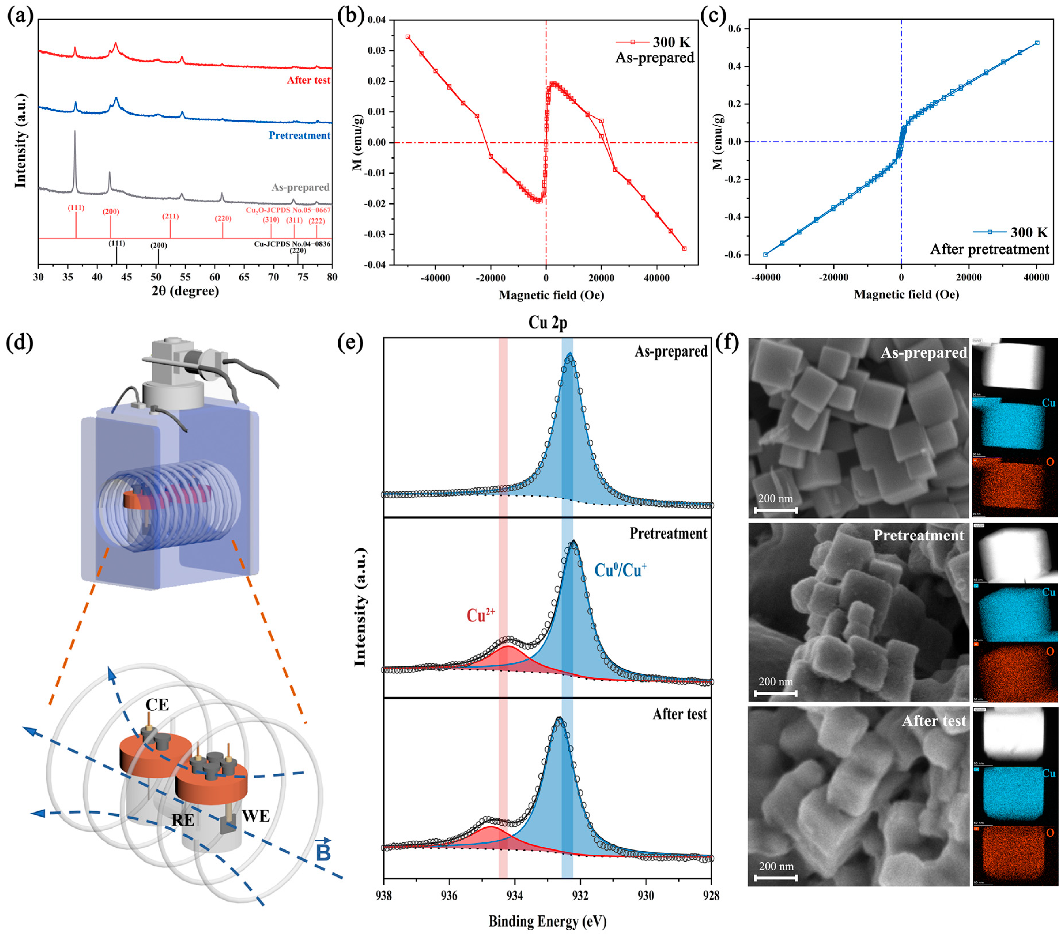
3.1. No Significant Structure Reconstruction during Testing

The Cu2O nanocubes will undergo a transition from Cu+ to Cu0 under a negative applied potential, accompanied by the change in surface oxidation state and surface reconstruction, which will highly affect the catalytic activity [26,31,32,33]. In order to exclude the influence of catalyst reconstruction, we pretreated the catalyst before the CO2RR test, and the current density and selectivity of the catalyst remained stable during testing (Figure S2). Moreover, material characterization of the as-prepared, pretreated, and after-test catalysts was studied.
Ex situ X-ray diffraction (XRD) was applied to detect the evolution of phase transition during the test. Figure 1a shows that the as-prepared catalyst is matched well with pure-phase Cu2O. After pretreatment and the CO2RR test, several new diffraction peaks appeared at 43.2°, 50.3°and 73.7°, is attributed to the formation of metallic copper. The coexistence of Cu and Cu2O diffraction peaks and their relative intensities were similar in the pretreated and after-test catalysts, indicating the inappreciable phase transformation. Additionally, the hysteresis behavior of the as-prepared and pretreated catalysts are shown in Figure 1b,c, respectively. The as-prepared catalysts are diamagnetic due to the full d shell Cu+ and nonmagnetic O2−, matching well with the XRD results. After pretreatment, the catalysts show paramagnetic properties (χ = 1.5 × 10⁻⁵ emu g−1 Oe−1) due to the increase in vacancy concentration in the Cu2O lattice [23,34]. Additionally, this behavior could be ascribed to the unpaired surface spin electron, which proved the possibility of spin polarization under magnetic fields.
Scanning electron microscopy (SEM), transmission electron microscopy (TEM) and STEM-HAADF were carried out to observe the change in morphology. The SEM (Figure 1f), STEM-HAADF (Figure S3) and TEM images (Figure S4) indicated that the as-prepared Cu2O are nanocubes with a diameter of 100–200 nm, and the predominating facets of the edge area are {111}. After pretreatment and 1 h IT test (−1.0 V versus RHE), the structure did not collapse significantly, but the surface gradually became rough. The STEM-EDX maps also indicated that unchanged Cu/O nanocubes structure during the test, and the Cu/O atomic ratio of the as-prepared catalyst was close to 2:1, which rises slightly after the test due to the reduction of Cu2O (Table S1).
X-ray photoelectron spectroscopy (XPS) was performed to study the chemical states on the catalyst surface during the test. Figure 1e presents the Cu 2p and Cu LMM of the as-prepared catalyst and catalysts after pretreatment and testing. The Cu 2p3/2 peaks at 932.1 and 934.2 eV could be attributed to the Cu+/Cu0 and Cu2+ species, respectively. For the as-prepared catalyst, only the Cu+/Cu0 peak could be observed. In combination with the weak satellite peaks (Figure S5) and the peak at 916.8 eV in Cu LMM, this indicates that the main phase of our catalyst is Cu2O, which is consistent with the XRD result [26,32]. After pretreatment and testing, the appearance of a peak at 918.6 eV in Cu LMM confirmed the transformation from Cu+ to Cu0 during the test. Additionally, the Cu2+ peak and stronger satellite peaks in the pretreated and after-test catalysts indicated the emergence of CuO, which arises from reoxidation by air during XPS testing.

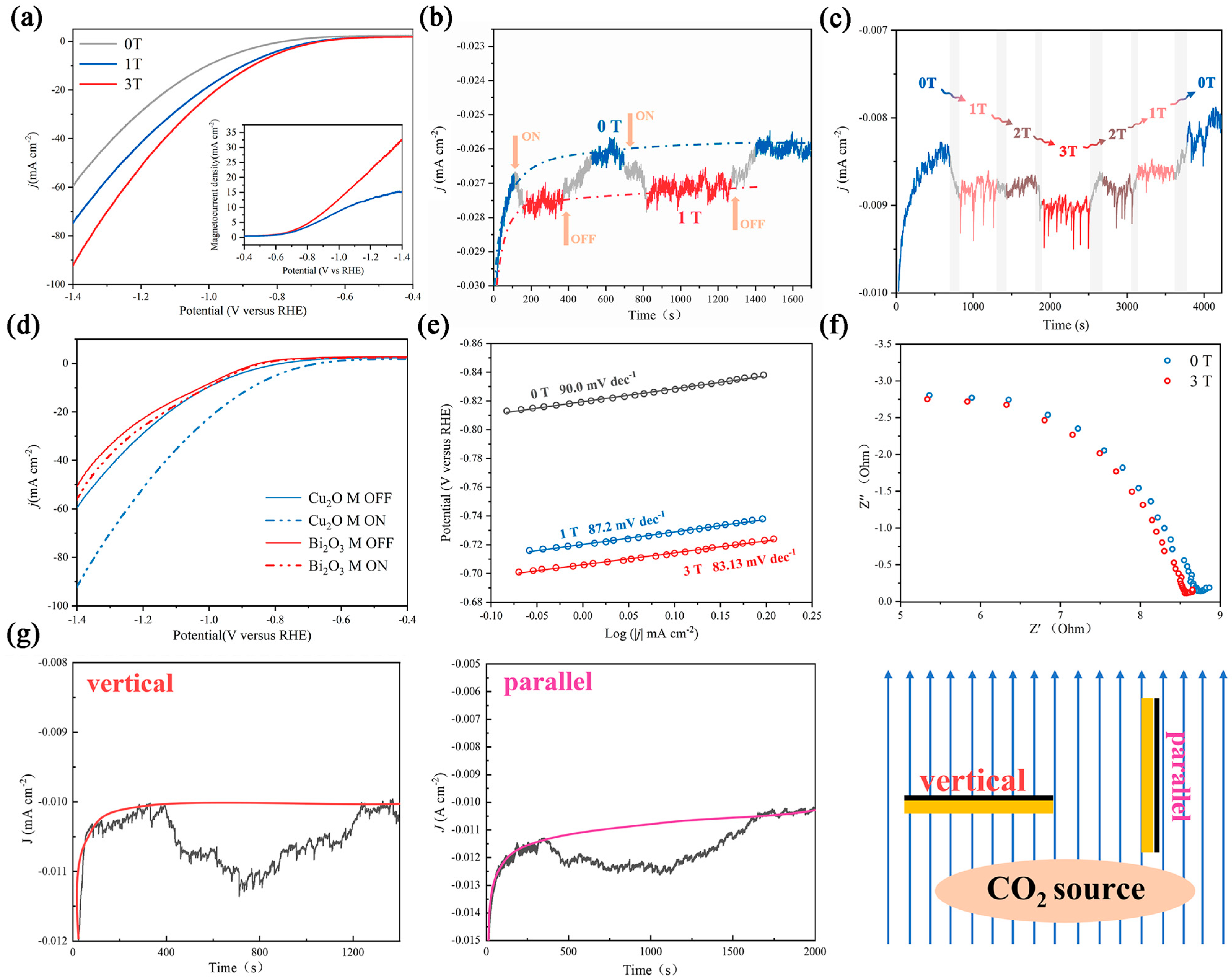
3.2. The Effect of a Magnetic Field on Electrocatalytic Performance

To investigate the effect of a magnetic field on the electrocatalytic performance of a catalyst, we performed electrochemical tests in an in situ magnetic field: the working electrode (carbon paper) was placed vertically to the magnetic induction line and tested in 0.5/0.1 M KHCO3 solution with carbon dioxide saturation. The magnetic field was generated by a mini cryogen-free system, which allowed us to accurately and quantitatively control the strength (B) of the magnetic field. The data of linear sweep voltammetry (LSV) are shown in Figure 2a. A significant increase in current density could be observed under magnetic fields. At −1.4 VRHE, the magnetocurrent reached 15.2 and 32.7 mA cm−2 in a 1 and 3 T magnetic field, respectively. The current density increased by 25.3% in the 1 T magnetic field and increased by 54.7% in the 3 T magnetic field. There are some phenomena that are noteworthy. The first is that the onset potential was positively shifted (114 mV) under magnetic fields, which is difficult to change by the Lorentz force [21]. We attribute this to the effect of radical pairs. Another is that the limit current of the magnetocurrent could be observed in the 1 T magnetic field, while it is invisible in a 3 T magnetic field.
The response time and intensity of magnetic effects were studied by intermittently applying a magnetic field during the test. In Figure 2b, when the magnetic field strength started to change, the current density increased immediately, and it regained the original current density after evacuation of the magnetic field, which indicates that the magnetic effect occurs straightaway and is reversible. In Figure 2c, a variational magnetic field was performed (in the order of 0 T-1 T-2 T-3 T-2 T-1 T-0 T). The trapezoidal-like curve indicates the positive correlation between magnetic field intensity and magnetocurrent density. However, the nearly identical density in the 1 and 2 T magnetic fields reveals that the relationship between J and B is not a simple linear relationship, which is also supported by Figure S6. The Tafel slope and electrochemical impedance spectroscopy (EIS) behavior are important indicators to evaluate the dynamics of the CO2RR [35,36]. As shown in Figure 2e, the Tafel slope in 0 T is 90.0 mv dec−1, and Cu2O exhibited a lower Tafel slope of 87.2 and 83.1 mv dec−1 in the 1 and 3 T magnetic fields, respectively. This result indicates that the magnetic field accelerates the reaction kinetics, which is likely because the majority of the sluggish 12 e transfer process (CO2 transform to C2H4 and C2H5OH) tends to convert to the more rapid 2 e transfer process. The EIS result also coincides with this phenomenon (Figure 2f). Charge transfer resistance is slightly decreased in a magnetic field.
To further illustrate the radical pairs effect, electrocatalysis under different magnetic field orientations was studied. A number of previous studies have shown that the Lorentz force effect is sensitive to the direction, and it can be eliminated by making the working electrode surface parallel to the magnetic sensing line [21,22,35]. We altered the orientation of the carbon paper in the magnetic field and found that an obvious magnetic field-enhanced phenomenon can be observed in both states (Figure 2g). In addition, other CO2RR catalysts without C–C coupling, such as Bi2O3, were also tested under different magnetic fields, and only a pimping magnetocurrent and an unchanged onset potential were observed (Figure 2d and Figure S7). All these phenomena indicate that there is a hybrid magnetic effect on Cu2O, and the Lorentz force effect is not the main effect.

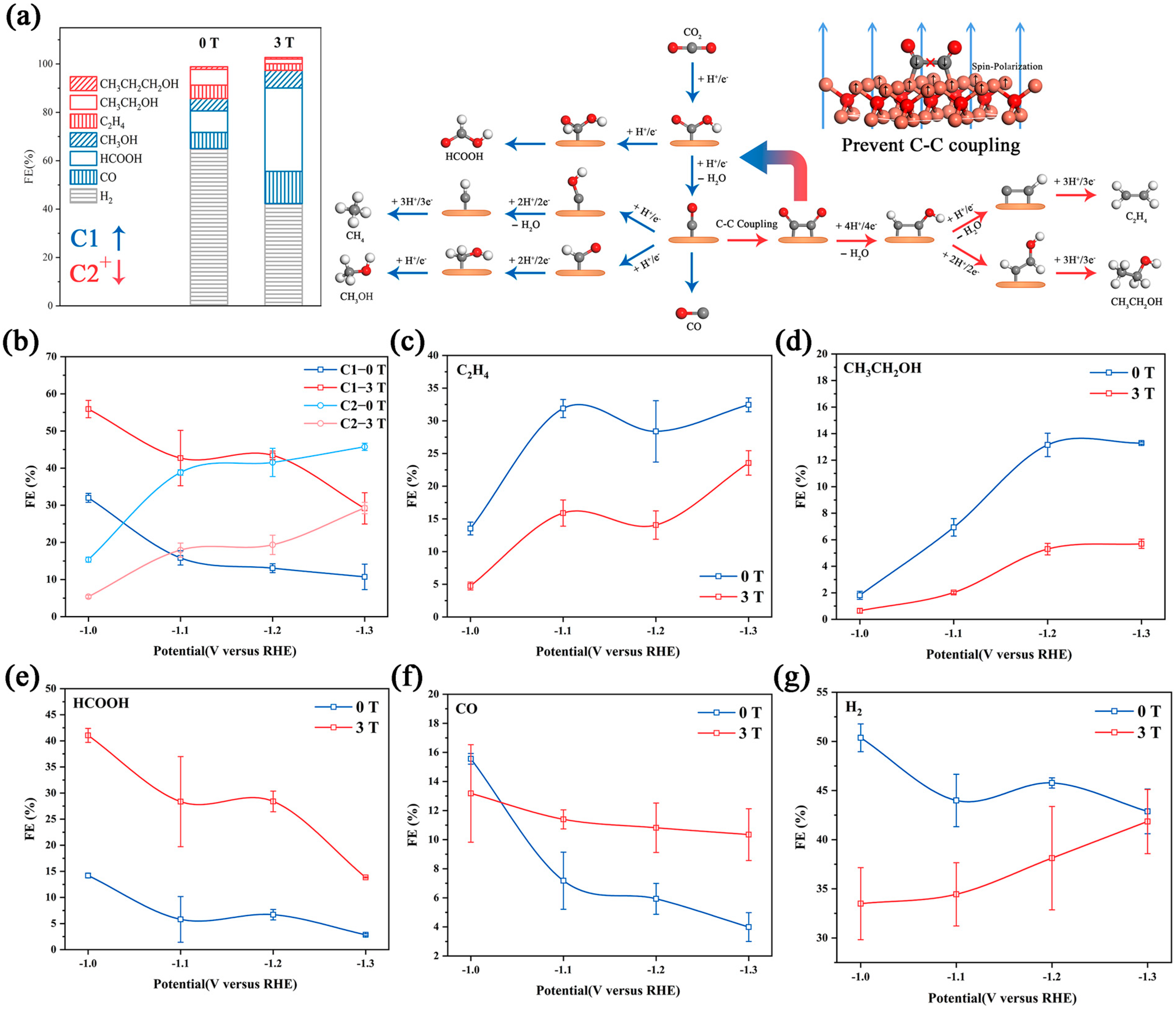
3.3. A hybrid Magnetic Effect in the CO2RR

The CO2RR has an intricate reaction path (Figure 3a) [2,37]. It is currently believed that the activation of a CO2 molecule is the first step. The adsorbed *CO2 is reduced to *OCHO or *COOH, which is further reduced to HCOOH and *CO, respectively [38,39]. Additionally, *CO is an important intermediate in the CO2RR, and it can be reduced to a C1 product (CH3OH and CH4) via subsequent proton-coupled electron transfer or it forms CO by desorption. Moreover, a pair of *CO on neighboring active sites can further couple to form C2+ (C2H4 and CH5OH) products [1,2,3,4,5,6,37]. We collected the products in various potentials with/without a magnetic field in a high overpotential region (−1.0 VRHE–−1.3 VRHE). The contrasting result (Figure 3b) shows that the Faraday efficiency of the C1 product (HCOOH and CO) is increased significantly with the decreasing Faraday efficiency for the H2 and C2+ products (C2H4, C2H5OH, and C3H8O). The detailed data are displayed in Figure 3c–g.
C2H4, C2H5OH and C3H8O were detected by GC and 1HNMR. The FE of C2+ was relatively low at −1.0 VRHE, and increased at a more negative applied potential. With a 3 T magnetic field, the FE of C2+ showed a similar variation tendency. The FE of C2H4 changed from 28.4% to 14.0% and the FE of C2H5OH changed from 13.1% to 5.3% at −1.2 VRHE. An similar inhibition also occurred in C3H8O (Figure S8). To explain this, we noticed that the reaction pathways of the C2+ product highly overlap, and have to go through C–C coupling [37]. Under a strong magnetic field, the polarized surface arranges the spin electron toward an identical orientation, which leads to the spin-forbidden *CO or *CHO turn to other reaction pathways [21,22,36]. CO and HCOOH showed different behavior. The FE of CO decreased suddenly at −1.1 VRHE. However, under the magnetic field, the FE of CO showed no significant changes at each voltage. Supporting the transformation of *CO into the C2+ product was inhibited. It is worth noting that the variation tendency of HCOOH was unchanged under a magnetic field, but the FEHCOOH under magnetic fields was 3-fold larger than the FEHCOOH without magnetic fields. There was a different variation tendency between the FECO and FEHCOOH possibly due to the different influences of the magnetic field on the adsorption energy of *OCHO and *COOH, which will be further discussed in the DFT result. The FE of the main competitive product, H2, was approximately 40~50% from −1.0 to −1.3 VRHE. The introduction of the magnetic field obviously suppressed H2 production at −1.0 and −1.1 VRHE, and this suppression gradually diminished as the potential decreased. At −1.3 VRHE, there was no difference between the FEH2 with/without a magnetic field.
The current density of the main product was further studied (Figure S9). The 3 T magnetic field has no obvious inhibition effect on the partial current density of H2, and the HER rate even increased at −1.3VRHE. Moreover, the magnetic field reduces the partial current density of C2 products and significantly increased the partial current density of C1 products, showing a similar variation trend to their Faraday efficiency. This result indicates that the magnetic field directly increased the reaction rate of C1 products and decreased the reaction rate of C2 products, without a significantly decreased HER rate. Previous studies have proven that the selectivity increase in the CO2RR by improving material transport was mainly due to the inhibition of HER, rather than the direct enhancement of the CO2RR [8]. This conclusion indicates that the increase in mass transport caused by circumfluence is not the main cause of the magnetic effect. We further analyzed the partial current density and the Faraday efficiency of each product at different stirring rates (Figure S10), and the different variation trend also supported this view.
DFT calculations were performed to explain the different influences of magnetic fields on FECO and FEHCOOH. We compared the Gibbs free energy of the CO and HCOOH reaction paths on spin-polarized and unspin-polarized Cu2O (111) crystal surfaces (Figure 4a). To model the spin-polarized catalyst surface, we used the “LSORBIT” and “SAXIS” keywords to set the magnetic moment of the surface atoms parallel to z [22]. The projected density of the states (PDOS) of the two key intermediates (*OCHO and *COOH) on the spin-polarized and unspin-polarized surface are shown in Figure 4b [38,39]. The spin polarization slightly reduced the d-band center of the surface copper atom and changed the overlap ratio between the Cu-3d orbit and the O-2p/C-2p orbit. This suggests that spin polarization can alter the adsorption energy of the intermediates by affecting the hybridization of surface atoms and the *OCHO/*COOH, thus affecting the selectivity of CO2RR products [40,41]. The free energy diagrams are shown in Figure 4c. For CO reaction paths, the rate-determining step (RDS) is the formation of *COOH, and the energy barriers of the spin-polarized and unspin-polarized surface are 0.817 and 0.568 eV, respectively. For HCOOH reaction paths, the binding energies of *OCHO on the spin-polarized surface is higher than on the unspin-polarized surface, which led to a lower energy barrier of RDS. Obviously, compared with the unspin-polarized surface, the spin-polarized surface lowers the energy barrier of the HCOOH reaction path (ΔG = −0.158 eV) and enhances the energy barrier of CO reaction paths (ΔG = 0.249 eV) (Figure 4d). This result indicated that the magnetic field-introduced spin polarization makes the CO2RR more inclined to follow the HCOOH reaction path, which is in good agreement with the experimental results.

4. Conclusions

In summary, we investigated the hybrid magnetic effect of the CO2RR on the Cu2O nanocubes. Our comparative test results and physical characterization exclude the magnetic effects dominated by Lorentz forces and phase transition during the test. The hysteresis loop of pretreated Cu2O and DFT results proves that magnetic fields lead to the spin polarization of surface electrons. The polarized surface affects the hybridization between surface copper atoms and *OCHO/*COOH and inhibits singlet C–C coupling. The spin-forbidden *CR intermediates are diverted to other reaction paths, resulting in the change in reaction kinetics and selectivity of the CO2RR. Under a 3 T magnetic field, the current density increased by 54.7% and the onset potential decreased by 114 mV. Moreover, the magnetic fields change product selectivity. That is, the Faraday efficiency of C2+ products (C2H4, C2H5OH, (CH3)2CHOH, etc.) is halved and the Faraday efficiency of C1 products (HCOOH, CO, etc.) is increased substantially. This work demonstrates the hybrid magnetic effect of the CO2RR on the spin-polarized surface and provides a new method to regulate the catalytic activity and selectivity.

Supplementary Materials

The following supporting information can be downloaded at: https://www.mdpi.com/article/10.3390/magnetochemistry9030065/s1, Figure S1: Installation photograph of a mini cryogen-free magnetic system. Figure S2: The current density and the Faraday efficiency of a 2.5 h IT test at 1.0 VRHE. Figure S3: HRTEM information of the pretreated Cu2O nanocubes. Figure S4: TEM images of the as-prepared Cu2O, pretreated Cu2O and after-test Cu2O. Figure S5: XPS spectra of Cu 2p and Cu LMM of the as-prepared, pretreated and after-test catalystd. Figure S6: The LSV curves of Cu2O in 0.5 M KHCO3 and 0.1 M KHCO3 and the plot of current density vs. time of Cu2O under different magnetic fields. Figure S7: LSV curves and the plot of current density vs. time of Bi2O3 under different magnetic fields. Figure S8: The FE of CH3CH2CH2OH and CH3OH at −1.0 VRHE under a 0 T/1 T/3 T magnetic field. Figure S9: Partial current density of different products of Cu2O under a 0 T/3 T magnetic field. Figure S10: The LSV curves of Cu2O under different rotational speeds. Figure S11: The optimized DFT models of Cu2O (111) surfaces with different intermediates. Table S1: The atomic fraction of Cu, O and the atomic error of the as-prepared, pretreated and after-test Cu2O catalysts. Table S2: The DFT energy, correction of zero point energy and entropy of the adsorbed and gaseous species.

Author Contributions

P.W., conceptualization, investigation, formal analysis, data curation, and writing—original draft preparation; X.M., investigation and resources; Y.Q., W.Z. and J.T., resources; L.H., conceptualization and resources; Q.C., conceptualization, resources, and writing—original draft preparation. All authors have read and agreed to the published version of the manuscript.

Funding

This study was funded by the National Natural Science Foundation (NSFC, 22272155, 22072140, 21972145), the National Key R&D Program of China (Grant No. 2021YFA1600202), and the Collaborative Innovation Program of Hefei Science Center, CAS (2021HSC-CIP002).

Institutional Review Board Statement

Not applicable.

Informed Consent Statement

Not applicable.

Data Availability Statement

The data presented in this study are available on request from the corresponding authors.

Acknowledgments

The authors are grateful to the National Natural Science Foundation, the National Key R&D Program of China and the Collaborative Innovation Program of Hefei Science Center for financial support. We would like to thank the University of Science and Technology of China and The High Magnetic Field Laboratory for equipment support.

Conflicts of Interest

The authors declare no conflict of interest.

References

  1. Chen, C.; Kotyk, J.K.; Sheehan, S.W. Progress toward Commercial Application of Electrochemical Carbon Dioxide Reduction. Chem 2018, 4, 2571–2586. [Google Scholar] [CrossRef] [Green Version]
  2. Zhu, D.D.; Liu, J.L.; Qiao, S.Z. Recent Advances in Inorganic Heterogeneous Electrocatalysts for Reduction of Carbon Dioxide. Adv. Mater. 2016, 28, 3423–3452. [Google Scholar] [CrossRef]
  3. Wang, Y.; Wang, Z.; Dinh, C.T.; Li, J.; Ozden, A.; Kibria, M.G.; Seifitokaldani, A.; Tan, C.; Gabardo, C.M.; Luo, M.; et al. Catalyst synthesis under CO2 electroreduction favours faceting and promotes renewable fuels electrosynthesis. Nat. Catal. 2020, 3, 98–106. [Google Scholar] [CrossRef]
  4. Garza, A.J.; Bell, A.T.; Head-Gordon, M. Mechanism of CO2 Reduction at Copper Surfaces: Pathways to C2 Products. ACS Catal. 2018, 8, 1490–1499. [Google Scholar] [CrossRef] [Green Version]
  5. Li, M.; Ma, Y.; Chen, J.; Lawrence, R.; Luo, W.; Sacchi, M.; Jiang, W.; Yang, J. Residual Chlorine Induced Cationic Active Species on a Porous Copper Electrocatalyst for Highly Stable Electrochemical CO2 Reduction to C2+. Angew. Chem. Int. Ed. 2021, 60, 2–9. [Google Scholar] [CrossRef]
  6. Jeon, H.S.; Timoshenko, J.; Scholten, F.; Sinev, I.; Herzog, A.; Haase, F.T.; Cuenya, B.R. Operando Insight into the Correlation between the Structure and Composition of CuZn Nanoparticles and Their Selectivity for the Electrochemical CO2 Reduction. J. Am. Chem. Soc. 2019, 141, 19879–19887. [Google Scholar] [CrossRef] [Green Version]
  7. Zhang, F.; Co, A.C. Direct Evidence of Local pH Change and the Role of Alkali Cation during CO2 Electroreduction in Aqueous Media. Angew. Chem. Int. Ed. 2020, 59, 1674–1681. [Google Scholar] [CrossRef]
  8. Goyal, A.; Marcandalli, G.; Mints, V.A.; Koper, M.T.M. Competition between CO2 Reduction and Hydrogen Evolution on a Gold Electrode under Well-Defined Mass Transport Conditions. J. Am. Chem. Soc. 2020, 142, 4154–4161. [Google Scholar] [CrossRef] [Green Version]
  9. Zhang, Y.; Liang, C.; Wu, J.; Liu, H.; Zhang, B.; Jiang, Z.; Li, S.; Xu, P. Recent Advances in Magnetic Field-Enhanced Electrocatalysis. ACS Appl. Energy Mater. 2020, 3, 10303–10316. [Google Scholar] [CrossRef]
  10. Elias, L.; Chitharanjan Hegde, A. Effect of Magnetic Field on HER of Water Electrolysis on Ni-W Alloy. Electrocatalysis 2017, 8, 375–382. [Google Scholar] [CrossRef]
  11. Kodaimati, M.S.; Gao, R.; Root, S.E.; Whitesides, G.M. Magnetic fields enhance mass transport during electrocatalytic reduction of CO2. Chem Catal. 2022, 2, 797–815. [Google Scholar] [CrossRef]
  12. Monzon, L.M.A.; Coey, J.M.D. Magnetic fields in electrochemistry: The Lorentz force. A mini-review. Electrochem. Commun. 2014, 42, 38–41. [Google Scholar] [CrossRef]
  13. Lu, F.; Wang, J.; Li, J.; Du, Y.; Kong, X.; Liu, S.; Yi, D.; Takahashi, Y.K.; Hono, K.; Wang, X.; et al. Regulation of oxygen reduction reaction by the magnetic effect of L10-PtFe alloy. Appl. Catal. B 2020, 278, 119332. [Google Scholar] [CrossRef]
  14. Matsushima, H.; Iida, T.; Fukunaka, Y.; Bund, A. PEMFC Performance in a Magnetic Field. Fuel Cells 2008, 8, 33–36. [Google Scholar] [CrossRef]
  15. Dunne, P.; Coey, J.M.D. Influence of a Magnetic Field on the Electrochemical Double Layer. J. Phys. Chem. C 2019, 123, 24181–24192. [Google Scholar] [CrossRef]
  16. Singh, M.R.; Clark, E.L.; Bell, A.T. Effects of electrolyte, catalyst, and membrane composition and operating conditions on the performance of solar-driven electrochemical reduction of carbon dioxide. Phys. Chem. Chem. Phys. 2015, 17, 18924–18936. [Google Scholar] [CrossRef] [PubMed] [Green Version]
  17. Buchachenko, A.L.; Berdinsky, V.L. Electron Spin Catalysis. Chem. Rev. 2002, 102, 604–612. [Google Scholar] [CrossRef] [PubMed]
  18. Steiner, U.E.; Ulrich, T. Magnetic Field Effects in Chemical Kinetics and Related Phenomena. Chem. Rev. 1989, 89, 51–147. [Google Scholar] [CrossRef] [Green Version]
  19. Pan, H.; Xiao, X.; Hu, B.; Shen, Y.; Wang, M. Generating Huge Magnetocurrent by Using Spin-Dependent Dehydrogenation Based on Electrochemical System. J. Phys. Chem. C 2017, 121, 28420–28424. [Google Scholar] [CrossRef]
  20. Pan, H.; Jiang, X.; Wang, X.; Wang, Q.; Wang, M.; Shen, Y. Effective Magnetic Field Regulation of the Radical Pair Spin States in Electrocatalytic CO2 Reduction. J. Phys. Chem. Lett. 2020, 11, 48–53. [Google Scholar] [CrossRef]
  21. Garcés-Pineda, F.A.; Blasco-Ahicart, M.; Nieto-Castro, D.; López, N.; Galán-Mascarós, J.R. Direct magnetic enhancement of electrocatalytic water oxidation in alkaline media. Nat. Energy 2019, 4, 519–525. [Google Scholar] [CrossRef] [Green Version]
  22. Ren, X.; Wu, T.; Sun, Y.; Li, Y.; Xian, G.; Liu, X.; Shen, C.; Gracia, J.; Gao, H.; Yang, H.; et al. Spin-polarized oxygen evolution reaction under magnetic field. Nat. Commun. 2021, 12, 2608. [Google Scholar] [CrossRef]
  23. Chen, C.; He, L.; Lai, L.; Zhang, H.; Lu, J.; Guo, L.; Li, Y. Magnetic properties of undoped Cu2O fine powders with magnetic impurities and/or cation vacancies. J. Phys. Condens. Matter 2009, 21, 145601. [Google Scholar] [CrossRef] [Green Version]
  24. Batsaikhan, E.; Lee, C.; Hsu, H.; Wu, C.; Peng, J.; Ma, M.; Deleg, S.; Li, W. Largely Enhanced Ferromagnetism in Bare CuO Nanoparticles by a Small Size Effect. ACS Omega 2020, 5, 3849–3856. [Google Scholar] [CrossRef] [PubMed] [Green Version]
  25. Rao, G.N.; Yao, Y.D.; Chen, J.W. Superparamagnetic Behavior of Antiferromagnetic CuO Nanoparticles. IEEE Trans. Magn. 2005, 41, 3409–3411. [Google Scholar] [CrossRef]
  26. Herzog, A.; Bergmann, A.; Jeon, H.S.; Timoshenko, J.; Kghl, S.; Rettenmaier, C.; Luna, M.L.; Haase, F.T.; Cuenya, B.R. Operando Investigation of Ag-Decorated Cu2O Nanocube Catalysts with Enhanced CO2 Electroreduction toward Liquid Products. Angew. Chem. Int. Ed. 2021, 60, 7426–7435. [Google Scholar] [CrossRef]
  27. Kresse, G.; Furthmüller, J. Efficient iterative schemes for ab initio total-energy calculations using a plane-wave basis set. Phys. Rev. B 1996, 54, 11169–11186. [Google Scholar] [CrossRef] [PubMed]
  28. Kresse, G.; Hafner, J. Ab initio molecular dynamics for liquid metals. Phys. Rev. B 1994, 49, 14251–14269. [Google Scholar] [CrossRef] [PubMed]
  29. Perdew, J.P.; Burke, K.; Ernzerhof, M. Generalized Gradient Approximation Made Simple. Phys. Rev. Lett. 1996, 77, 3865–3868. [Google Scholar] [CrossRef] [Green Version]
  30. Hammer, B.; Hansen, L.B.; Nørskov, J.K. Improved adsorption energetics within densityfunctional theory using revised Perdew-Burke-Ernzerhof functionals. Phys. Rev. B 1999, 59, 7413–7421. [Google Scholar] [CrossRef] [Green Version]
  31. Kim, C.; Dionigi, F.; Beermann, V.; Wang, X.; Möller, T.; Strasser, P. Alloy Nanocatalysts for the Electrochemical Oxygen Reduction (ORR) and the Direct Electrochemical Carbon Dioxide Reduction Reaction (CO2RR). Adv. Mater. 2019, 31, 1805617. [Google Scholar] [CrossRef]
  32. Zhu, Q.; Sun, X.; Yang, D.; Ma, J.; Kang, X.; Zheng, L.; Zhang, J.; Wu, Z.; Han, B. Carbon dioxide electroreduction to C2 products over copper-cuprous oxide derived from electrosynthesized copper complex. Nat. Commun. 2019, 10, 3851. [Google Scholar] [CrossRef] [PubMed] [Green Version]
  33. Luna, P.D.; Quintero-Bermudez, R.; Dinh, C.; Ross, M.B.; Bushuyev, O.S.; Todorović, P.; Regier, T.; Kelley, S.O.; Yang, P.; Sargent, E.H. Catalyst electro-redeposition controls morphology and oxidation state for selective carbon dioxide reduction. Nat. Catal. 2018, 1, 103–110. [Google Scholar] [CrossRef] [Green Version]
  34. Qin, H.; Zhang, Z.; Liu, X.; Zhang, Y.; Hu, J. RoomTemperature Ferromagnetism in CuO Sol-Gel Powders and Films. J. Magn. Magn. Mater. 2010, 322, 1994–1998. [Google Scholar] [CrossRef]
  35. Zhang, Y.; Guo, P.; Li, S.; Sun, J.; Wang, W.; Song, B.; Yang, X.; Wang, X.; Jiang, Z.; Wu, G.; et al. Magnetic field assisted electrocatalytic oxygen evolution reaction of nickel-based materials. J. Mater. Chem. A 2022, 10, 1760–1767. [Google Scholar] [CrossRef]
  36. Jiang, S.; Chen, F.; Zhu, L.; Yang, Z.; Lin, Y.; Xu, Q.; Wang, Y. Insight into the Catalytic Activity of Amorphous Multimetallic Catalysts under a Magnetic Field toward the Oxygen Evolution Reaction. ACS Appl. Mater. 2022, 14, 10227–10236. [Google Scholar] [CrossRef]
  37. Kibria, M.G.; Edwards, J.P.; Gabardo, C.M.; Dinh, C.; Seifitokaldani, A.; Sinton, D.; Sargent, E.H. Electrochemical CO2 Reduction into Chemical Feedstocks: From Mechanistic Electrocatalysis Models to System Design. Adv. Mater. 2019, 31, 1807166. [Google Scholar] [CrossRef]
  38. Zheng, X.; Ji, Y.; Tang, J.; Wang, J.; Liu, B.; Steinrück, H.; Lim, K.; Li, Y.; Toney, M.F.; Chan, K.; et al. Theory-guided Sn/Cu alloying for efficient CO2 electroreduction at low overpotentials. Nat. Catal. 2019, 2, 55–61. [Google Scholar] [CrossRef]
  39. Wu, Z.; Wu, H.; Cai, W.; Wen, Z.; Jia, B.; Wang, L.; Jin, W.; Ma, T. Engineering Bi-Sn Interface in Bimetallic Aerogel with 3D Porous Structure for Highly Selective Electrocatalytic CO2 Reduction to HCOOH. Angew. Chem. Int. Ed. 2021, 60, 12554–12559. [Google Scholar] [CrossRef]
  40. Liu, B.; Xie, Y.; Wang, X.; Gao, C.; Chen, Z.; Wu, J.; Meng, H.; Song, Z.; Du, S.; Ren, Z. Copper-triggered delocalization of bismuth p-orbital favours high-throughput CO2 electroreduction. Appl. Catal. B 2022, 301, 120781. [Google Scholar] [CrossRef]
  41. Gao, L.; Wang, C.; Li, R.; Li, R.; Chen, Q. The effect of external magnetic fields on the catalytic activity of Pd nanoparticles in Suzuki cross-coupling reactions. Nanoscale 2016, 8, 8355–8362. [Google Scholar] [CrossRef] [PubMed]
Figure 1. Material characterization of the catalyst: (a) XRD pattern of the as-prepared, pretreated and after-test catalyst. (b,c) The M(H) curves at 300 K of the as-prepared and pretreated catalyst. (d) The schematic diagram of the magnetic field device and electrochemical H-cell. (e) XPS spectra of Cu 2p of the as-prepared, pretreated and after-test catalyst. (f) SEM images and EDS mapping of the as-prepared, pretreated and after-test Cu2O nanocubes.
Magnetochemistry 09 00065 g001
Figure 2. Electrochemical characterization of the catalyst under different magnetic fields. (a) LSV curves and magnetocurrent curves under 0 T, 1 T, and 3 T magnetic fields. (b) Plot of current density vs. time in a 1 T intermittent magnetic field; the yellow arrow corresponds to the switching time. (c) Plot of current density vs. time in a magnetic field; the gray area corresponds to the interim time. (d) LSV curves of Cu2O and Bi2O3 with/without a magnetic field. (e) Tafel slope of Cu2O under different magnetic fields. (f) EIS plot of Cu2O under 0 and 3 T magnetic fields. (g) Plot of current density vs. time in vertical and parallel orientations toward the magnetic sensing line.
Magnetochemistry 09 00065 g002
Figure 3. (a) The Faraday efficiency in −1.1V VRHE under different magnetic fields and the reaction roadmaps of the CO2RR on Cu2O catalysts; the red roads are inhibited in the magnetic field by preventing C–C coupling. The Faraday efficiency plot with/without a magnetic field of C1, C2 (b), C2H4 (c), CH3CH2OH (d), HCOOH (e), CO (f) and H2 (g). All tests were performed in 0.1 M KHCO3, and the error bars represent the s.d. (n = 3).
Magnetochemistry 09 00065 g003
Figure 4. (a) Schematic diagram of the HCOOH and CO reaction paths. (b) Projected density of the states (PDOS) of the Cu2O (111) with adsorbed COOH and OCHO. The Fermi level is referenced at 0 eV. (c) Free energy diagrams for the CO2RR to CO and HCOOH on spin-polarized and unspin-polarized Cu2O (111) crystal surfaces. (d) The ΔG of RDS for the HCOOH and CO reaction paths. The blank, slash-filled and horizontal-filled columns represent the ΔG values of RDS on spin-polarized and unspin-polarized catalysts and the difference in values, respectively.
Magnetochemistry 09 00065 g004
Disclaimer/Publisher’s Note: The statements, opinions and data contained in all publications are solely those of the individual author(s) and contributor(s) and not of MDPI and/or the editor(s). MDPI and/or the editor(s) disclaim responsibility for any injury to people or property resulting from any ideas, methods, instructions or products referred to in the content.

