Article

Study on the Mechanism of Rootstock Damage during Clamping in Watermelon Grafting

1
College of Biosystems Engineering and Food Science, Zhejiang University, Hangzhou 310058, China
2
School of Additive Manufacturing, Zhejiang Institute of Mechanical & Electrical Engineering, Hangzhou 310053, China
3
Key Laboratory of Equipment and Informatization in Environment Controlled Agriculture, Ministry of Agriculture, Hangzhou 310058, China
4
Key Laboratory of Intelligent Equipment and Robotics for Agriculture of Zhejiang Province, Zhejiang University, Hangzhou 310058, China
*
Author to whom correspondence should be addressed.
Horticulturae 2022, 8(7), 617; https://doi.org/10.3390/horticulturae8070617
Submission received: 20 May 2022 / Revised: 30 June 2022 / Accepted: 4 July 2022 / Published: 7 July 2022

Abstract

:
Rootstock has a soft tissue that should be held carefully to avoid mechanical damage. Holding the rootstock stem is a significant factor in the grafting process, with direct consequences on the survival rate of grafting. To analyze the damage mechanism of clamping rootstock, a finite element model of the clamping mechanism was established, and different clamping velocities and silicone rubber thicknesses were then studied in this study using the finite element method (FEM). The density and elasticity modulus of the rootstock stem and silicone rubber were determined experimentally using standard methods. The results show that as the clamping velocity increased, the contact force on the rootstock stem increased, and the clamping velocity should be lower than the critical velocity to reduce the probability of damage occurrence on the stem. The increase in silicone rubber thickness would decrease the force on the stem, while also resulting in the instability of the rootstock clamping. A silicone rubber thickness of 4 mm was confirmed as an appropriate thickness for this device. The simulation results were compared with the experimental results, and the mean error was 7.01% within the allowable range, which indicated that the FEM simulation model was reliable.

1. Introduction

Watermelon (Citrullus lanatus) is an important economic crop that accounts for about 9.5% of the total global vegetables production [1]. China is the main producer of watermelon, contributing up to nearly 60.6% of the yield worldwide [2]. Fusarium oxysporum f. sp. Niveum (Fon) is the cause of Fusarium wilt of watermelon, which is a common limiting factor for watermelon production worldwide [3,4], causing a loss of 10–15% of watermelon yield [5,6]. Currently, grafting is the main means to defend against soil-borne diseases and enhance watermelon quality due to its resistance to biotic and abiotic stresses [7,8].
In China, the grafted watermelon seedlings are commonly used for watermelon production; however, watermelon grafting is mainly manually performed due to the low level of the grafting mechanization. The main reason for low mechanization is that foreign grafting machines have a high cost and are not applied in the domestic environment; moreover, no mature domestically developed grafting machines have been popularized in the country, which is seriously hindering the development of mechanized grafting [9]. A rootstock clamping device is a crucial part of a watermelon grafting machine. Rootstock seedlings are prone to damage due to the soft material of rootstock during clamping, thus affecting the grafting quality. Therefore, studies on the rootstock clamping devices are warranted. Springs were designed by Lou et al. [10] at both ends of the clamping mechanism, automatically adjusting the position during the clamping process based on the inclined insertion method. Jiang et al. [11] and Chu et al. [12] both designed a flexible clamping device using the close joining method. Additionally, the rubber gaskets were arranged in the middle of the clamping mechanism, which can reduce clamping damage to some extent. However, these studies on rootstock clamping devices are based only on experiments, and there have been no studies conducted on the damage mechanism during the rootstock clamping process.
Finite element (FE) analysis is a numerical approach and is widely used to solve complex engineering problems. In the farm industry, the linear response of the material is limited to small deformation, and the increase in deformation leads to nonlinear behavior of materials; thus, the response to the loading is usually nonlinear [13,14]. Chen and Baerdemaeker [15] used the FE technique to evaluate the melon firmness, and the bruised area of pear fruit was predicted by Yousefi et al. [16]. Li et al. [17] studied the mechanical damage in tomatoes under external compressive force, and Sadrnia et al. [18] used nonlinear finite element analysis to investigate internal bruising in compressed watermelons. Cui and Shen [19] modeled and predicted the buckling and post-buckling behavior of plant stems under loading. Dynamic tests and FE simulations were conducted by Celik et al. [20] to analyze the dynamic deformation of potato during mechanical collision. Dintwa et al. [21] used the FE method to analyze the dynamic collision of apple fruits considering the viscoelastic properties. Zajaczkowska et al. [22] studied the mechanical characteristics of Equisetum hyemale stems during vibration based on FE analysis. These studies above showed that the FE method is an appropriate method to estimate deformations and mechanical damage of plants.
Currently, fewer studies have been carried out in the clamping collision of grafting rootstocks, and the interaction analysis of the clamping device and the rootstock seedlings is relatively scarce. In this study, finite element simulation was performed to evaluate the force on the rootstock stem at different velocities and silicone rubber thicknesses. The experimental results were compared with simulation results to determine the reasonable range of the clamping velocity and silicone rubber thickness. The results of this study provide new information for the damage evaluation of rootstock clamping in grafting.

2. Materials and Methods

2.1. Rootstock Clamping Mechanism Model

2.1.1. Rootstock Clamping Mechanism

Before removing the rootstock growth point, the rootstock needs to be held using the inclined insertion grafting method. A rootstock seedling clamping mechanism was designed in our previous study [23], as shown in Figure 1. The clamping mechanism mainly involves clamping blocks, silicone rubbers, and cylinders. During clamping, the pneumatic cylinder drove clamping block ‘a’ toward clamping block ‘b’ to hold the rootstock seedling. To achieve undamaged clamping of the rootstock seedlings, silicone rubber was installed on the clamping blocks, which had a certain buffering effect during the clamping process. Negative pressure air holes were present on the upper surface of the clamping blocks to adsorb the cotyledons of the rootstock to facilitate the subsequent growth point removal process. The clamping blocks were attached to a rotary table cylinder through the connecting frame and secured to the cylinder fixing frame.

2.1.2. Clamping Process Analysis

During the clamping process, the pneumatic cylinder drove clamping block ‘a’ close to clamping block ‘b’. After coming into contact with the rootstock stem, it started to squeeze the stem and continued to move to deform the silicone rubber until the movement of the pneumatic cylinder stopped [24]. The movement process consisted of three stages. The force analysis of the rootstock seedlings in the three stages is shown in Figure 2.
(a)
Before collision: the cylinder drove clamping block ‘a’ to move toward clamping block ‘b’ at a certain velocity, which is the acceleration stage. At this time, the rootstock stem was closely attached to the inner side of the silicone rubber under the external suction action. The force equation is as follows.
{ F 1 = F F f 1 = G
  • F1—The supporting force of silicone rubber to the stem, N;
  • F—The external suction force, N;
  • Ff1—The friction force between silicone rubber and the stem, N;
  • G—The rootstock seedlings gravity, N.
(b)
Collision occurred: clamping block ‘a’ started to come into contact with the rootstock stem and continued to squeeze, and the silicone rubber deformed under pressure. Silicone rubber is an elastic composite material with nonlinear characteristics, and thus, the force F1 is a nonuniform variation value. When clamping block ‘a’ collided with clamping block ‘b’, the movement stopped. At this stage, the acceleration of clamping block ‘a’ gradually decreased, and the velocity first increased and then decreased. To prevent damage to the stem under pressure, the stress of the stem should be less than the yield stress of the stem. The force equation on the stem can be expressed as
{ F t S + F S 0 < σ e F f 2 = G
Then,
m a S + P < σ e
  • Ft—The driving force of the cylinder over time, N;
  • S—The contact area between silicone rubber and the stem, m2;
  • S0—The contact area between air hole and the stem, m2;
  • G—The rootstock seedlings gravity, N;
  • σe—Yield stress of the stem, Pa;
  • m—Mass of silicone rubber and clamping block ‘a’, kg;
  • a—Acceleration of silicone rubber and clamping block ‘a’, m/s2;
  • P—Negative pressure, Pa.
(c)
After collision: the clamping collision was completed, and the deformation of silicone rubbers reached a stable state. At this time, the force equation is presented below.
{ F 1 = F + F 2 F f 3 = G
  • F″1—The supporting force of right silicone rubber to the stem, N;
  • F2—The force of left silicone rubber to the stem, N;
  • Ff3—The friction force between silicone rubbers and the stem, N.
From the above force analysis, the force at the stage of collision occurred may have caused damage to the stem. Thus, further analysis was mainly performed for this stage. Since silicone rubber is geometrically nonlinear during deformations, Hooke’s law cannot be used for the calculation, and it is difficult to determine the nonlinear characteristics of elastic materials. Therefore, other methods are needed to calculate the force of the stem.

2.2. Plant Material

Cucurbit (Yongzhen No. 5, Top-Yield Seed Technology Co., Ltd., Ningbo, China) was used as the rootstock. Rootstock seeds were soaked for 14 h before accelerating germination, and the seeds were sown in 50-cell trays after germination. The test was carried out when the cucurbit seedlings had one true leaf unfolded and the second true leaf exposed.

2.3. Finite Element Modeling

2.3.1. Geometric Model of Clamping Mechanism

A 3D model of the clamping mechanism was established in the software SolidWorks 2016 (Dassault Systemes SolidWorks Corp., Concord, MA, USA). For the convenience of calculation and analysis, the clamping model was simplified, as shown in Figure 3. The geometric dimensions of 120 rootstock seedlings were measured. The average long axis and short axis values of the stem were 3.52 mm and 2.94 mm, respectively. The average long axis and short axis values of the medullary cavity were 0.79 mm and 0.77 mm, respectively. The stem length was set at 30 mm.

2.3.2. Settings of the Element Type and Material Properties

Model pre-processing is an important part of FE simulation. In this study, the 3D clamping model was saved in IGES format and then imported into the HyperMesh software 13.0 (Altair Engineering Inc., Troy, MI, USA) for model pre-processing. Silicone rubber is an elastic material, and it is assumed to be incompressible, which means that its volume is kept constant before and after deformation. The Mooney–Rivlin model was commonly used to describe the properties of rubber-like materials [25,26]. The model parameters obtained through the test are shown in Table 1. *MAT_PLASTIC_KINEMATIC was selected as the simulation material of rootstock stem. The clamping block material was harder compared to the other two materials. Thus, to facilitate the simulation calculation, *MAT_RIGID was chosen as the simulation model material. The model material parameters measured for the stem and silicone rubber are listed in Table 2.
When solving the deformation problem, single-point integration is often used for element calculation to avoid the negative volume of the element. Solid164 element is chosen in explicit dynamic analyses with eight nodes, whose default algorithm is single-point integration [27]. Therefore, the clamping block, silicone rubber, and rootstock in this simulation all used Solid164 units.

2.3.3. Grid Division

The grid size directly influences the finite element analysis results. Theoretically, the smaller the grid size, the closer the predicted value is to the real value [28]. However, a smaller size also increases computation time. To choose the appropriate grid size of the clamping model, further study of grid size convergence is warranted. For this purpose, the influence of the stem with different grid sizes on the contact force was investigated in this study [29]. The different grid sizes of the stem are shown in Figure 4 and Table 3.

2.3.4. Contact Settings of the Element Type and Material Properties

To save computation time, the initial distance between the two silicone rubbers was 0.1 mm. The right clamping block was fixed, and the stem and the right silicone rubber fitted together. It was assumed that clamping block ‘a’ with a certain velocity approached clamping block ‘b’ and made frontal collision contact. In HyperMesh software 13.0, a penalty contact function was used to cope with the model contact. Studies have shown that if the penalty factor is more than 1.0, the calculation results may be unstable [27,30]. Considering friction, the penalty factor was set to 0.1, and a friction coefficient of 1.4 was measured for the contact between the stem and silicone rubber. The contact type AUTOMATIC_SURFACE_TO_SURFACE was employed for all contact surfaces. According to the clamping velocity, the termination time, time step, and the output parameters can be set accordingly. The processed FE model was imported into ANSYS 16.0 (ANSYS, Inc., Township, PA, USA) and then calculated using LS-DYNA Solver.

3. Results and Discussion

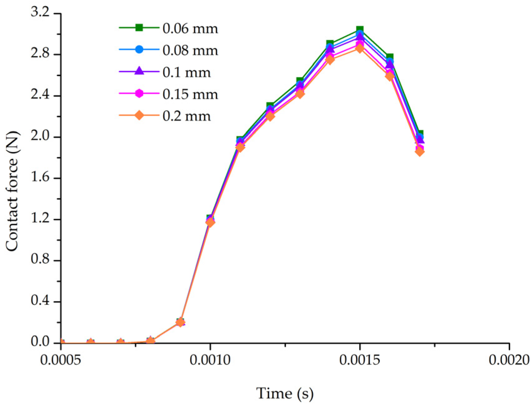
3.1. Grid Independence Validation

FE results were imported into LS-PrePost software (Livermore Software Technology Corporation, Livermore, CA, USA) for analysis, and contact force in x direction curves of different elements during clamping with a velocity of 110 mm/s and a silicone rubber thickness of 3 mm were obtained, as shown in Figure 5. Due to the frontal collision, only the contact force in the x direction was analyzed. From Figure 5, the contact force gradually approached the exact solution with the decrease in grid size. The maximum contact force was 3 N at the grid size of 0.08 mm, which differed from the results at 0.06 mm by less than 2%; however, the model computing time was greatly reduced. Thus, the FE model with a grid size of 0.08 mm was selected for analysis in this study.

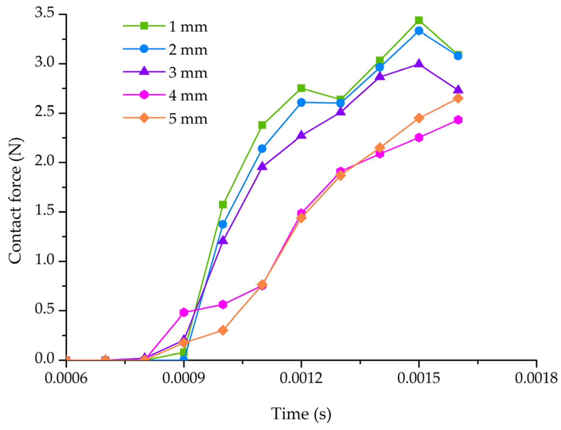
3.2. FE Simulation Results and Discussion

To investigate the action of the clamping model on the stem, FE simulations of the clamping process with different clamping velocities and silicone rubber thicknesses were performed. Figure 6 shows the von Mises stress distribution of the stem at a clamping velocity of 110 mm/s. From Figure 6, it can be seen that the stress acting on the stem was zero before collision, indicating that there was no internal stress. At t = 0.0008 s, the two ends of the left silicone rubber began to make contact with the stem, and the contact zone of the silicone rubber and the stem was subjected to compressive stress. With time, the von Mises stress distribution spread toward the surroundings, and the stress gradually increased. Additionally, the maximum stress shifted from the beginning at both ends to the frontal area of the collision. At t = 0.0015 s, the peak stress occurred. Subsequently, as time increased, the stress gradually decreased. The stress did not disappear immediately but propagated inside the stem in the form of a stress wave [27].
Figure 7 presents, under the condition of 3 mm silicone rubber thickness, the contact force in the x direction for the stem with different clamping velocities. It can be seen from Figure 7 that under the same velocity, the contact force increased first and subsequently decreased with increasing time. The silicone rubber fixed onto clamping block ‘a’ came into contact with the stem, and the contact force rapidly increased. The greater the velocity, the more obvious the phenomenon was. Moreover, it was found that the maximum contact force increased as the velocity increased. The reason for this was that the momentum of the object increased with increasing velocity, and according to the impulse–momentum theorem, increased momentum increased the force while keeping time constant. This conclusion was supported by similar data from Azimi et al. [31]. The maximum contact forces under different velocities are shown in Figure 8. From Figure 8, with an increase in velocity, the maximum contact force increased almost linearly. According to previous studies, the critical force for a stem was 4.45 N [32]. Thus, the corresponding velocity of 190 mm/s could be obtained by fitting to the curve. However, the size of the stem was uneven, and the reduced critical force caused a reduction in the velocity. To prevent damage to the stem, the clamping velocity should be kept below the critical velocity.
Figure 9 presents, under the condition of 110 mm/s clamping velocity, the contact force in the x direction for the stem with different silicone rubber thicknesses. As can be seen from Figure 9, under the same silicone rubber thickness, the contact force gradually increased with increasing time. However, from 1 mm to 4 mm, the contact force overall decreased as the silicone rubber thickness increased. This was because the thicker silicone rubber could produce larger deformation and store greater deformation energy when the same force acted on the silicone rubber. Thus, the force acting on the stem decreased accordingly. Similar conclusions can also be drawn by Zakeri et al. and Chen et al. [33,34]. Due to small thickness variations, the contact forces at 1 mm and 2 mm were not significantly different. The maximum contact force at 3 mm distinctly decreased. The tendency of the contact force curves at the silicone rubber of 5 mm changed when compared to the other group. Through this experiment, it was found that thicker silicone rubber caused the stem to rotate during clamping, and the stem was not held effectively. Thus, 4 mm is a more suitable silicone rubber thickness for the clamping device.
The analysis of variance results, indicating the effect of clamping velocity and silicone rubber thickness on the maximum contact force, are shown in Table 4. From Table 4, the p-values for clamping velocity and silicone rubber thickness were both less than 0.05, indicating that clamping velocity and silicone rubber thickness significantly affected the maximum contact force (p < 0.05). Therefore, the results from FEM are statistically significant.

3.3. Test Validation

To verify the rationality and reliability of the established FE simulation model, a study on the clamping device with different clamping velocities was conducted. The clamping device test-bed is shown in Figure 10. To measure the velocity of the pneumatic cylinder, an acceleration sensor (50 g, Chengke Electronic Technology Co., Ltd., Shanghai, China) was adopted. The contact force was measured by a force sensor (2 kg, Chengke Electronic Technology Co., Ltd., Shanghai, China) [32]. The comparison of the simulation and experimental results for the maximum contact force in the x direction with different velocities is shown in Figure 11. From Figure 11, the simulation results display a similar trend to the experimental results. In addition, the simulation results are very close to the experiments, with a mean error of 7.01%. Thus, it was reasonable to conclude that the model established in this study was suitable to simulate the rootstock clamping process.
In watermelon grafting methods, generally, the rootstock needs to be fixed first, and then, the scion and the rootstock are combined together. This easily causes damage to the rootstock during clamping. Finite element modeling is a feasible way to evaluate the effect of various clamping parameters on the rootstock. Naturally, this method is also applied to the analysis of the scion clamping process.

4. Conclusions

Rootstock clamping plays a crucial role in watermelon grafting. The performance of the clamping device determines the extent of damage occurring during clamping. Thus, optimizing the clamping device parameters is an effective way to reduce the damage. In this study, we proposed FE simulation to replace the actual experiment for optimizing the device. For this purpose, a rootstock clamping model was established. FE simulations with different clamping velocities and silicone rubber thicknesses were then performed. The simulation results show that the von Mises stress first increased and then decreased over time, and the maximum stress shifted from both sides in the beginning to the frontal area of the stem. Increased velocity increased the maximum contact force of the stem. To reduce damage to the stem, the clamping velocity should be lower than the critical velocity. Moreover, when the silicone rubber thickness was small, thickness variation had a minor influence on the contact force of the stem. A greater silicone rubber thickness may cause the stem to rotate during clamping and reduce the clamping effect. A silicone rubber thickness of 4 mm was confirmed to be optimal for reducing damage to the stem. Finally, the validation of the simulation model was carried out by comparing the simulation results with experimental results. The mean error between the simulation results and the experimental results was 7.01%, indicating that the simulation model was reliable. This study provides a basis for developing a clamping device with low damage.

Author Contributions

Methodology, K.W. and J.L. (Jianping Li); software, K.W., W.L., C.L. (Congcong Li) and C.L. (Chen Li); validation, K.W.; formal analysis, K.W. and C.L. (Chen Li); investigation, K.W.; data curation, K.W.; writing—original draft preparation, K.W.; writing—review and editing, J.L. (Jianzhong Lou) and J.L. (Jianping Li); visualization, K.W.; supervision, J.L. (Jianping Li); project administration, J.L. (Jianping Li); funding acquisition, J.L. (Jianping Li). All authors have read and agreed to the published version of the manuscript.

Funding

This research was funded by National Natural Science Foundation of China (Grant No. 51775490).

Institutional Review Board Statement

Not applicable.

Informed Consent Statement

Not applicable.

Data Availability Statement

The data presented in this study are available on demand from the first author at (kang_wu@zju.edu.cn).

Acknowledgments

The authors gratefully acknowledge the financial support provided by the National Natural Science Foundation of China (Grant No.51775490). We also appreciate the work of the editors and the reviewers of the paper.

Conflicts of Interest

The authors declare no conflict of interest.

References

  1. Aslam, A.; Zhao, S.; Azam, M.; Lu, X.; He, N.; Li, B.; Dou, J.; Zhu, H.; Liu, W. Comparative analysis of primary metabolites and transcriptome changes between ungrafted and pumpkin-grafted watermelon during fruit development. PeerJ 2020, 8, e8259. [Google Scholar] [CrossRef] [PubMed]
  2. Food and Agriculture Organization (FAO). STAT. 2020. Available online: http://www.fao.org/faostat/en/#data/QC (accessed on 30 December 2021).
  3. Michielse, C.B.; Rep, M. Pathogen profile update: Fusarium oxysporum. Mol. Plant Pathol. 2009, 10, 311–324. [Google Scholar] [CrossRef] [PubMed]
  4. Netzer, D.; Weintall, C. Inheritance of resistance in watermelon to race 1 of Fusarium oxysporum f. sp. niveum. Plant Dis. 1980, 64, 853–854. [Google Scholar] [CrossRef]
  5. Martyn, R.D.; Netzer, D. Resistance to races 0, 1, and 2 of Fusarium wilt of watermelon in Citrullus sp. PI-296341-FR. HortScience 1991, 26, 429–432. [Google Scholar] [CrossRef] [Green Version]
  6. Chang, T.; Lin, Y.; Wan, Y.; Chen, K.; Huang, J.; Chang, P. Degenerated virulence and irregular development of Fusarium oxysporum f. sp. niveum induced by successive subculture. J. Fungi 2020, 6, 382. [Google Scholar] [CrossRef]
  7. Rouphael, Y.; Venema, J.; Edelstein, M.; Savvas, D.; Colla, G.; Ntatsi, G.; Ben-Hur, M.; Kumar, P.; Schwarz, D. Grafting as a Tool for Tolerance of Abiotic Stress. Vegetable Grafting: Principles and Practices; Colla, G., Perez-Alfocea, F., Schwarz, D., Eds.; CAB International: Wallingford, UK, 2017; pp. 171–215. [Google Scholar] [CrossRef]
  8. Aloni, B.; Cohen, R.; Karni, L.; Aktas, H.; Edelstein, M. Hormonal signaling in rootstock scion interactions. Sci. Hortic. 2010, 127, 119–126. [Google Scholar] [CrossRef]
  9. Zhang, K.; Chu, J.; Zhang, T.; Yin, Q.; Kong, Y.; Liu, Z. Development status and analysis of automatic grafting technology for vegetables. Trans. CSAM 2017, 48, 1–10. [Google Scholar] [CrossRef]
  10. Lou, J.Z.; Wu, K.; Chen, J.Y.; Ma, G.; Li, J.P. Design and test of self-adaptive stock cotyledons pressing and clamping mechanism for oblique inserted grafting of cucurbitaceous vegetables. Trans. CSAE 2018, 34, 76–82. [Google Scholar] [CrossRef]
  11. Jiang, K.; Chen, L.; Zhang, Q.; Feng, Q.; Guo, W.; Cao, L. Design and experiment on flexible clamping and conveying mechanism of vegetable grafting robot. Trans. CSAM 2020, 51, 63–71. [Google Scholar] [CrossRef]
  12. Chu, J.; Zhang, L.; Zhang, T.; Zhang, W.; Wang, L.; Liu, Z. Design and experiment of grafting robot operated by one person for cucurbitaceous seedlings cultivated in plug trays. Trans. CSAM 2017, 48, 7–13. [Google Scholar] [CrossRef]
  13. Nikara, S.; Ahmadi, E.; Nia, A.A. Finite element simulation of the micromechanical changes of the tissue and cells of potato response to impact test during storage by scanning electron microscopy. Postharvest Biol. Technol. 2020, 164, 111153. [Google Scholar] [CrossRef]
  14. Lu, R.; Chen, Y. Characterization of nonlinear elastic properties of beef products under large deformation. Trans. ASAE 1998, 41, 163–171. [Google Scholar] [CrossRef]
  15. Chen, H.; Baerdemaeker, J.D. Modal analysis of the dynamic behavior of pineapples and its relation to fruit firmness. Trans. ASAE 1993, 36, 1439e144. [Google Scholar] [CrossRef]
  16. Yousefi, S.; Farsi, H.; Kheiralipour, K. Drop test of pear fruit: Experimental measurement and finite element modelling. Biosyst. Eng. 2016, 147, 17–25. [Google Scholar] [CrossRef]
  17. Li, Z.; Li, P.; Yang, H.; Liu, J. Internal mechanical damage prediction in tomato compression using multiscale finite element models. Int. J. Food Eng. 2013, 116, 639e647. [Google Scholar] [CrossRef]
  18. Sadrnia, H.; Rajabipour, A.; Jafari, A.; Javadi, A.; Mostofi, Y.; Kafashan, J.; Dintwa, E.; Baerdemaeker, J.D. Internal bruising prediction in watermelon compression using nonlinear models. Int. J. Food Eng. 2008, 86, 272–280. [Google Scholar] [CrossRef]
  19. Cui, H.; Shen, H. Modeling and simulation of buckling and postbuckling of plant stems under combined loading conditions. Int. J. Appl. Mech. 2011, 3, 119–130. [Google Scholar] [CrossRef]
  20. Celik, H.K.; Cinar, R.; Yilmaz, D.; Ulmeanu, M.E.; Rennie, A.W.; Akinci, I. Mechanical collision simulation of potato tubers. J. Food Process Eng. 2019, 42, e13078. [Google Scholar] [CrossRef]
  21. Dintwa, E.; Van, Z.M.; Ramon, H.; Tijskens, E. Finite element analysis of the dynamic collision of apple fruit. Postharvest Biol. Technol. 2008, 49, 260–276. [Google Scholar] [CrossRef]
  22. Zajaczkowska, U.; Kucharski, S.; Nowak, Z.; Grabowska, K. Morphometric and mechanical characteristics of Equisetum hyemale stem enhance its vibration. Planta 2017, 245, 835–848. [Google Scholar] [CrossRef] [Green Version]
  23. Wu, K.; Lou, J.Z.; Li, C.; Li, J.Z. Experimental evaluation of rootstock clamping device for inclined inserted grafting of melons. Agriculture 2021, 11, 736. [Google Scholar] [CrossRef]
  24. Liu, J.; Bai, X.; Li, P.; Mao, H. Complex collision model in high-speed gripping of fruit. Trans. CSAM 2014, 45, 49–54. [Google Scholar] [CrossRef]
  25. Carlone, P.; Palazzo, G.S. Finite element analysis of the thermoforming manufacturing process using the hyperelastic Mooney-Rivlin model. In Proceedings of the 6th international conference on Computational Science and Its Applications, Glasgow, UK, 8–11 May 2006. [Google Scholar] [CrossRef]
  26. Keerthiwansa, R.; Javorik, J.; Kledrowetz, J.; Nekoksa, P. Elastomer testing: The risk of using only uniaxial data for fitting the Mooney-Rivlin hyperelastic-material model. Mater. Tehnol. 2018, 52, 3–8. [Google Scholar] [CrossRef]
  27. Xu, L.; Li, Y.; Ma, Z.; Zhao, Z.; Wang, C. Theoretical analysis and finite element simulation of a rice kernel obliquely impacted by a threshing tooth. Biosyst. Eng. 2013, 114, 146–156. [Google Scholar] [CrossRef]
  28. Wang, B.; Wang, J.; Du, D.D. Finite element analysis of dynamic impact damage process of maize kernel based on HyperMesh and LS-DYNA. J. Zhejiang Univ. (Agric. Life Sci.) 2018, 44, 465–475. [Google Scholar] [CrossRef]
  29. Celik, H.K. Determination of bruise susceptibility of pears (Ankara variety) to impact load by means of FEM-based explicit dynamics simulation. Postharvest Biol. Technol. 2017, 128, 83–97. [Google Scholar] [CrossRef]
  30. Li, S.; Deng, R. Dynamic simulation and application of colliding process of cam and rolling bearing in circuit breaker. High. Volt. Apparat. 2008, 6, 497e500. [Google Scholar]
  31. Azimi, N.H.; Karparvarfard, H.; Naderi, B.M.; Rahmanian, K.H. Combined finite element and statistical models for predicting force components on a cylindrical mouldboard plough. Biosyst. Eng. 2019, 186, 168–181. [Google Scholar] [CrossRef]
  32. Wu, K.; Lou, J.Z.; Li, C.; Luo, W.; Li, C.C.; Li, J.P. Study on the mechanism of rootstock holding damage in watermelon grafting. Agriculture 2021, 11, 1266. [Google Scholar] [CrossRef]
  33. Zakeri, R.; Moghaddas Tafreshi, S.N.; Dawson, A.R.; Baidya, D.K. Influence of rubber sheet on dynamic response of machine foundations. Constr. Build. Mater. 2020, 274, 121788. [Google Scholar] [CrossRef]
  34. Chen, X.; Ding, M.; Wang, S.; Luo, Z.; Yang, D. Modeling and analysis on the elastic performance of SMT silicone rubber keypad. In Proceedings of the 18th International Conference on Electronic Packaging Technology (ICEPT), Harbin, China, 16–19 August 2017. [Google Scholar] [CrossRef]
Figure 1. Three-dimensional model of the clamping mechanism [23]. 1. Pneumatic cylinder. 2. Clamping block ‘a’. 3. Silicone rubber. 4. Connecting frame. 5. Rootstock seedling. 6. Clamping block ‘b’. 7. Negative pressure air hole. 8. Rotary table cylinder. 9. Cylinder fixing frame.
Horticulturae 08 00617 g001
Figure 2. Analysis of the forces on the rootstock seedlings during clamping.
Horticulturae 08 00617 g002
Figure 3. A simplified model of the clamping mechanism. (unit: mm). 1. Clamping block. 2. Silicone rubber. 3. Rootstock stem.
Horticulturae 08 00617 g003
Figure 4. Different grid sizes of the stem.
Horticulturae 08 00617 g004
Figure 5. Contact force in x direction curves of five elements during clamping with velocity of 110 mm/s and silicone rubber thickness of 3 mm.
Horticulturae 08 00617 g005
Figure 6. Von Mises stress distribution (MPa) of stem during clamping with velocity of 110 mm/s and silicone rubber thickness of 3 mm.
Horticulturae 08 00617 g006
Figure 7. Contact force in the x direction curves for stem with different velocities.
Horticulturae 08 00617 g007
Figure 8. Relationship between the maximum contact force in the x direction and clamping velocity.
Horticulturae 08 00617 g008
Figure 9. Contact force in the x direction for stem with different silicone rubber thicknesses.
Horticulturae 08 00617 g009
Figure 10. Clamping device test-bed. 1. Pneumatic cylinder. 2. Acceleration sensor. 3. Clamping block. 4. Silicone rubber. 5. Rootstock seedling. 6. Force sensor. 7. Frame.
Horticulturae 08 00617 g010
Figure 11. Comparison of simulation and experimental results for the maximum contact force in the x direction with different velocities.
Horticulturae 08 00617 g011
Table 1. Model parameters of silicone rubber.
DensityPoisson RatioC01 (Constant)C10 (Constant)
Silicone rubber1380 kg/m30.492.04−0.38
Table 2. Model parameters of clamping block and rootstock stem.
DensityModulus of ElasticityPoisson Ratio
Clamping block1250 kg/m3902.48 MPa0.42
Rootstock stem1970 kg/m310.29 MPa0.3
Table 3. Different grid sizes of the stem.
Grid Size0.060.080.10.150.2
Element amount480,000270,000180,00072,00045,000
Node amount511,020293,280198,66084,42054,360
Table 4. ANOVA results for the maximum contact force.
SourceSum of SquaresdfMean SquareF-Valuep-ValueSignificant
Velocity3.01650.60312065.2860.007Yes
Thickness0.95840.2404792.1670.011Yes
Error5 × 10−51
Total138.20111
Publisher’s Note: MDPI stays neutral with regard to jurisdictional claims in published maps and institutional affiliations.

