1. Introduction
Two-dimensional (2D) carbon-based materials have garnered significant attention owing to their exceptional physical and chemical properties, which have found utility in the realm of flat electronics [
1]. Among these materials, graphene emerges as one of the most prominent choices [
1]. Graphene exhibits remarkable characteristics, comprising a single layer of carbon atoms arranged in a hexagonal lattice, including outstanding electrical conductivity, robust mechanical strength, and excellent thermal properties [
2,
3]. The combination of these properties positions graphene as an up-and-coming candidate for a diverse array of applications, encompassing electronics [
2], energy storage [
4], and sensor technology [
2,
5].
Several other 2D carbon allotropes, such as
-graphyne [
6], monolayers of biphenylene [
7], amorphous carbon [
8], and fullerene networks [
9], have been successfully synthesized. Despite these achievements, ongoing efforts are focused on creating new materials that can overcome certain limitations associated with graphene. Notably, graphene’s absence of an electronic bandgap hinders its application in digital devices, and researchers are actively seeking alternatives to address this issue.
One study introduced the concept of pentagraphene (PG), a material entirely composed of pentagonal carbon rings arranged in a pattern reminiscent of Cairo pentagonal tiling [
10]. This unique material offers a compelling combination of high stability, a negative Poisson’s ratio, and anisotropic conductivity. It possesses a semiconducting and indirect band gap measuring 3.25 eV, along with Young’s modulus and Poisson’s ratio values of approximately 263.8 GPa·nm and −0.068, respectively. Although the synthesis of PG has not yet been realized, its innovative properties have sparked further research to develop new materials with similar topological features. These efforts involve fused pentagonal rings, which aim to retain the attractive properties of PG.
A recent theoretical study introduced a novel 2D carbon allotrope named pentagraphyne (PG-yne) [
11]. In comparison to other graphyne variants, including experimentally synthesized graphyne monolayers [
6] and graphdiyne [
12], PG-yne exhibits greater thermodynamic stability and energy favorability. It derives from PG by introducing acetylenic linkages between sp
and sp
hybridized carbon atoms, much like graphynes originate from graphene [
13].
Computational calculations have confirmed PG-yne’s dynamic, thermal, and mechanical stability, enabling it to withstand temperatures of up to 1000 K [
11]. Furthermore, PG-yne exhibits inherent semiconducting properties, characterized by an electronic bandgap of approximately 1.0 eV, which can be fine-tuned by applying strain. These exceptional attributes drive our comprehensive exploration of PG-yne’s mechanical properties and fracture patterns to broaden the understanding of its potential applications and inspire further investigations into its synthesis.
In this study, we have conducted fully atomistic reactive molecular dynamics (MD) simulations employing the ReaxFF force field. Our primary objective was to investigate the mechanical properties, fracture patterns, and thermal behavior of PG-yne monolayers and nanotubes. Our simulations encompassed a monolayer and spanned a range of tube diameters and chiralities within the PG-yne system. At room temperature, we determined Young’s modulus of the monolayers to be approximately 50 GPa. The nanotubes considered in this study exhibited values hovering around 45 GPa. The well-known impact of rising temperature on the elastic constants, as reported in existing literature [
14], was also evident in our findings. A noteworthy observation emerged after subjecting both PG-yne and
PG-yneNTs and
PG-yneNTs to specific strain levels. In each case, a distinct flat plastic region was between the elastic and fully fractured areas, brought about by a phase transition within PG-yne. This phase transition led to a transformation of the material into an amorphous graphyne-like structure. A comparable transformation was observed when increasing the temperature. Under a constant temperature ramp, the system converted at around 1100 K, completely melting the structure at approximately 3600 K.
2. Methodology
To explore the mechanical properties and fracture patterns of PG-yne monolayers and PG-yneNTs, we conducted fully atomistic reactive molecular dynamics (MD) simulations. These simulations were carried out using the LAMMPS code [
15] in conjunction with the ReaxFF potential [
16]. The ReaxFF potential is widely employed to study nanostructures’ mechanical properties due to its capability to model atomic-level bond formation and breakage [
17]. In our simulation setup, we utilized a PG-yne supercell model (refer to
Figure 1). For the nanotubes, we explored two distinct chirality types, namely
and
, as depicted in
Figure 1.
We performed extensive tests of various force fields, including Tersoff [
18], AIREBO [
19], and two ReaxFF potentials [
20,
21]. Throughout these simulations, we encountered several challenges when attempting to model the system accurately. For instance, when using AIREBO, we observed a system collapse in the direction perpendicular to the applied uniaxial stress. On the other hand, applying the Tersoff force field led to deviations within the system during the equilibration simulation. After a thorough assessment, the force field presented in [
20] emerged as the most suitable choice among our explored options. This force field accurately represented triple bonds and the unique penta-graphene allotrope structure, allowing us to achieve the desired results.
In our computational modeling of PG-yneNTs, we establish the chiral vector, denoted as , as , where and represent the lattice vectors, and n and m are integers that dictate the chirality of the nanotube. The nanotube’s diameter, , is determined as . Furthermore, we establish the translational vector, , which is perpendicular to , and this is defined as , with and being integers derived from the inner product relationship . The length of the nanotube is represented as , and the chiral and translational vectors jointly define the nanotube’s unit cell. It is worth noting that because the PG-yne unit cell is square (), configurations labeled as and for PG-yneNTs are fundamentally equivalent, with the only distinction being a rotational difference.
Figure 1 provides an illustrative overview of the systems under investigation, emphasizing key elements relevant to their thermal and mechanical characteristics. In
Figure 1a, we present the unit cell of the system, consisting of 26 atoms and featuring a symmetrical structure with a side length of 9.85 Å. Within PG-yne, acetylene linkages are introduced between sp
hybridized (
) and sp
hybridized (
) atoms. These acetylenes give rise to triple bonds of the sp
type. When viewed from the side, PG-yne, much like pentagraphene, deviates from being perfectly flat. We denote the difference between the maximum and minimum values in the direction perpendicular to the 2D plane as
. In calculations of the stress–strain curve, this value is added to the graphene thickness (
Å), making it an essential parameter.
Figure 1c showcases the monolayer of PG-yne employed in this study. The red square denotes the unit cell. At the same time, the chiral directions for the nanotubes, namely
and
, are indicated by dashed red lines. Frontal views of these nanotube configurations are presented in items
Figure 1d,e.
In the case of the 2D system, a supercell of dimensions was employed, with an area of 117.4 nm measuring 108.35 Å on each side, comprising a total of 3146 atoms. Periodic boundary conditions were applied for the x and y directions, and mirror boundary conditions for z. For the nanotubes, the systems , , and with diameters of 12.5, 25.0, and 37.6 Å, respectively, were considered. Furthermore, the , , and nanotubes, with diameters of 13.3, 26.6, and 35.5 Å, respectively, were also studied. These values were chosen to compare nanotubes with different chiralities and similar diameters. In the cases, where the unit cell coincides in terms of length with the 2D unit cell (9.85 Å), a supercell was considered, totaling 1144, 2288, and 3432 atoms for the , , and systems, respectively. The , , and systems have 1248, 2496, and 3328 atoms, respectively, with a total length of 111.44 Å in all cases. In all nanotubes, periodic boundary conditions were applied in the z-direction, with mirror boundary conditions in the x and y directions.
In our computational approach, we first minimized the energy of the PG-yne and PG-yneNTs systems. Subsequently, we coupled them to a thermostat chain for thermodynamic equilibrium. We performed constant NPT ensemble integration at null pressure and 300 K to ensure no remaining stress. We used a Nose/Hoover [
22] pressure barostat for 50 ps. Following this, we coupled all the systems in the canonical NVT ensemble for an additional 50 ps. This approach enabled the generation of sampled positions and velocities at room temperature. In all simulations, the time step was set to 0.05 fs.
For the study of thermal stability, after equilibration and thermalization at room temperature and zero pressure, the system is subjected to a temperature ramp using a canonical ensemble, ranging from 300 K to 7000 K over a 2 ns simulation, equivalent to a rate of 3.35 K/ps. To characterize the system’s response, considering the first law of thermodynamics,
, it is possible to express the internal energy as a function of temperature and volume as:
In the case of the canonical ensemble, the volume is constant, i.e., the heat capacity can defined as
, and so it helps identify phase transitions in the system when the energy response varies significantly with temperature.
To investigate the overall mechanical behavior of PG-yne and PG-yneNTs, we conducted tensile tests by stretching the systems until rupture. The tests were performed using a constant engineering tensile strain rate of /fs concerning the simulation box in the strain direction. An NPT ensemble was employed for the 2D case, maintaining zero pressure in the direction orthogonal to the strain direction, and an NVT ensemble was used for the 1D case, also varying the chirality ( and ). In this way, the strain rate was applied to PG-yne along the x-direction and to PG-yneNTs along the z-direction. We analyzed the stress–strain curves to extract the elastic properties of each structure at room temperature. Furthermore, we described bond breaks and defined fracture patterns of the PG-yne and PG-yneNTs structures by analyzing the snapshots from MD simulations.
In the generation of the stress–strain curves, we calculated the percentage of strain and the stress tensor
divided by the volume, where
a takes on values
x or
z, depending on whether it’s a 2D or 1D system [
23]. In the two-dimensional case, the volume is given by
, where
, with
representing the system’s buckling,
as the thickness of graphene, and
and
denotes the lengths in
x- and
y-direction, respectively. In the 1D system,
, with the radius
R, and length
in
z-direction. The term
is defined as:
where
is the neighbor of atom
i,
and
, are the positions of the two atoms in the pairwise interaction, and
and
are the forces resulting of this pairwise interaction.
,
,
, and
are the number of bonds, angles, dihedrals, and impropers of
i-atom, respectively. To visualize the MD snapshots, we used the VMD software version 1.9.4 [
24].
3. Results
We start the discussion by analyzing the PG-yne structure after optimization at 0 K, equilibration at zero pressure and room temperature, and thermalization at constant volume at room temperature. In
Figure 1a, the unit cell of PG-yne contains 26 atoms, and the bond lengths are distributed essentially in three values. In the case of the bonds between acetylene atoms, there is a bond length of approximately 1.22 Å, and these bonds are known for their sp
hybridization. In PG-yne, the bonds involving atoms denoted as
and
have bond lengths of around 1.45 Å and 1.54 Å.
Graphyne-like systems have an interesting aspect: replacing a bond with an acetylene bond leads to a more energetically favorable atomic angle rearrangement [
25]. Here, the angles centered on atoms of type-
are close to 120
, whereas the angles centered on type-
atoms are approximately 108
, typical values for sp
and sp
hybridization, respectively. These results are consistent with the original work [
11] and indicate the structural stability of PG-yne with the coexistence of bonds involving sp
and sp
hybridized carbon atoms. On the other hand, the two types of nanotubes,
and
, exhibit almost the same configuration, with the expected difference in the widening of the outer bonds, compensated by the narrowing of the inner bonds. The angles are only slightly altered.
A characteristic of PG, which extends to PG-yne, is the presence of a buckling structure (see
Figure 1b). After the system equilibration,
Å. Additionally, a 50 ps simulation was conducted with the finite PG-yne monolayer using a canonical ensemble at room temperature to verify the integrity of the buckling in the case of a non-periodic system. The value of
remained unchanged.
As mentioned in the previous section, we conducted a temperature ramp simulation to explore the thermal properties of PG-yne. This simulation considers the thermally equilibrated system at room temperature and zero pressure as input. The total simulation time is 2 ns, with the temperature incrementing at a rate of 3.35 K/ps concerning the system’s thermal bath. We monitored the system’s temperature and total energy during this simulation, computing these values following the equipartition theorem.
Subsequently, we established a linear fit between temperature and time, which allowed us to confirm the correlation between temperature and energy. This relationship is illustrated by the green curve in
Figure 2. Notably, there are two shifts in the energy variation rate with increasing temperature: the first corresponds to a phase change in the 2D system’s topology. In contrast, the second indicates the transition to a gaseous state.
We quantified these values by employing Equation (
1), which calculates the heat capacity by assessing the rate of energy change concerning temperature within a system held at a constant volume. The results are depicted in
Figure 2 (illustrated by the orange curve).
The observed PG-yne phase transition manifests as a transformation into an amorphous graphyne-like system, taking place around 1100 K. Consequently, the resulting topology proves to be more energetically stable than PG-yne when temperatures exceed 1000 K. The most substantial shift in energy occurs at 3616 K when the original PG-yne transitions to a gaseous state. This behavior aligns with that of PG, which exhibits two notable phase changes: the first at 1593 K, resulting in a more stable configuration within that temperature range, and the second at 4944 K, signifying the onset of the melting process [
26].
Figure 3 provides a visual representation of selected snapshots depicting the behavior of the PG-yne monolayer throughout the heating simulation, as quantified in
Figure 2. The system’s initial state was already thermally equilibrated at 300 K and maintained zero pressure in the
x and
y directions. As previously noted, the system undergoes a significant phase transition around 1100 K.
Figure 3a captures the system’s state at 2000 K, portraying a discernible transformation. Many acetylene structures and atoms of type
with sp
hybridization remain intact. In contrast, those of type
exhibiting sp
hybridization have experienced bond breakage. This observation suggests that the latter group of atoms is less susceptible to the temperature increase in this particular system.
In
Figure 3b, as the system approaches the point of collapse (occurring at 3600 K), we observe a solid system characterized by a notable presence of linear atomic chains (LACs) and small graphene domains. This behavior can be attributed to the stability and proximity of sp
hybridized atoms within the structure. Moving on to
Figure 3c at 5000 K, we observe that the system has melted, resulting in multiple clusters comprising dispersed LACs scattered throughout the simulation box. At 7000 K, the system has transitioned into a gaseous state. See the
supplementary material for more information on this process. Notably, beyond the initial phase transition up to 1000 K, the melting pattern resembles that of various other two-dimensional carbon allotropes [
27,
28]. Notably, the change in system topology does not significantly alter its response to increasing temperature.
Regarding the mechanical properties of PG-yne,
Figure 4 presents the stress–strain curve for the 2D case. In these simulations, uniaxial stress is applied in the
x direction, inducing deformation in the periodic box at a rate of
fs
. Given the system’s symmetry, a simulation with deformation in the
y direction would yield analogous results. To prevent the accumulation of stress in the direction perpendicular to the strain, we used an NPT ensemble, ensuring zero pressure in the
y direction is maintained.
In general, acetylene is typically associated with a rigid structure. However, it forms micropores within the lattice when it replaces bonds in 2D carbon allotropes characterized by sp
and sp
hybridization. This presence of micropores is known to reduce the overall rigidity of the materials. The specific case of PG-yne consists of rings containing 16 atoms. Given a buckling of 6.8 Å and a 1% strain, Young’s modulus of PG-yne is approximately 51 GPa. This value represents only one-tenth of the reported Young’s modulus for pure PG, which exhibits a much smaller buckling of 0.6 Å, measuring approximately 500 GPa. This value was calculated using both Density Functional Theory (DFT) [
29] and classical (reactive) MD [
30] approaches.
Similar to the scenario with temperature increase, a critical transformation in the system occurs with a relatively modest strain percentage of around 12%. At this stage, we observe the conversion to an amorphous graphyne-like system. Consequently, the elastic region of PG-yne is constrained to an approximate maximum of 12%. This limitation arises due to the implementation of the NPT approach, preventing stress accumulation in the y direction. This constraint prompts the system to reconfigure itself, averting persistent high-stress conditions. The system can endure significant strain before reaching complete fracture, accommodating up to 108% of strain. Beyond this point, up to 130% of strain, the system still encounters stress due to linear atomic chains (LACs) forming during rupture. The ultimate strength supported by the system approximates 32 GPa.
The adaptability of periodic 2D graphyne-type structures and their related mechanical properties have been examined regarding the stress–strain curve, as depicted in
Figure 4. Complementing this,
Figure 5 provides insights into the fracture patterns. In
Figure 5a, we observe the system in an equilibrium state characterized by zero constant pressure. At this point, it has been thermally equilibrated to room temperature with no applied strain.
In
Figure 5b, a 30% strain is introduced to the system, leading to the conversion of the material into an amorphous graphyne-like structure. This transformation involves a distinct pattern of transitioning atoms of type
with sp
hybridization into atoms featuring sp
hybridization. Additionally, the system loses its inherent buckling. This yielded product from PG-yne accumulates more significant stress than the original system, prompting the reorganization of bonds to prevent abrupt stress escalation.
Moving on to
Figure 5c, one can note that the linear atomic chains (LACs) formed are increasingly aligned with the direction of strain, accompanied by the onset of a Poisson effect. This effect is marked by continuously reducing the simulation box’s dimensions in the
y direction. At 100% strain (
Figure 5d), the system takes on a highly porous quality characterized by extended LACs in the region that will eventually fracture entirely at 108%, as previously discussed. Finally,
Figure 5e captures the system in a fully fractured state, marked by the rupture of the last remaining LAC connecting the system at 130%. Notably, when considering an NVT ensemble for the crack of this system (see
Supplementary Material), the breakage occurs abruptly due to the accumulation of stress in the direction perpendicular to the applied strain. For more details about the PG-yne fracture process, see
Supplementary Material.
The transition in the topology of PG-yne has a relatively modest impact on the system’s response to longitudinal strain. When simulating nanotubes, we maintained most parameters, except the ensemble, which was changed to NVT due to the one-dimensional nature of the system. Periodic boundary conditions were preserved in the z-direction.
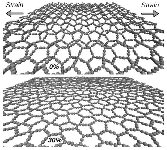
Figure 6 showcases two nanotubes with differing chiralities but similar diameters. In
Figure 6a, we observe the
PG-yneNT at 0% strain, with the system in equilibrium and thermally equilibrated. In
Figure 6b, at 30% strain, we witness the same phase transition previously discussed for monolayers. This transition involves the disruption of the sp
hybridization of type-
atoms.
Advancing to 50% strain
Figure 6c, we note the alignment of linear atomic chains (LACs) with the direction of strain. Finally, in
Figure 6d, at 91.5% strain, the system is on the verge of complete fracture, with only a few LACs remaining. The critical observation is the infinite nature of stress dissipation in the y-direction for monolayers. In contrast, despite their ability to adapt concerning diameter, nanotubes cannot as effectively accommodate changes in the direction perpendicular to the applied strain, particularly compared to the two-dimensional case. Consequently, despite a similar fracture pattern, nanotubes tend to fracture significantly earlier than the 2D case.
A similar pattern is evident when considering the
PG-yneNT case.
Figure 6e–g represent the system in equilibrium, the phase transition triggered by sp
hybridization disruption, and the alignment of linear atomic chains (LACs) alongside the formation of increasing micropores.
Figure 6h depicts the system with 73.5% strain, teetering on the brink of complete fracture following the emergence of LACs. In all these instances, the Poisson effect is observable, manifesting as a distinct reduction in tube diameter with increasing deformation.
In addition to the nanotube discussions presented earlier,
Figure 7 provides stress–strain curves. The left panel illustrates the
cases, whereas the right panel displays the
cases. As mentioned, all systems employ 1% strain with a
Å thickness. Young’s modulus for all systems is about 45 GPa in this case. The marginal variance compared to the monolayer can be attributed to the system’s topology, as it possesses limited capacity for adjustments in the direction perpendicular to the strain. Furthermore, within the study of PG-yneNTs’ mechanical properties, two distinct groups can be identified based on behavior.
An interesting observation for cases with smaller diameters is the topology change resulting from the disruption of sp
hybridization. However, it is worth noting that the system’s stress does not immediately become flat after this transition, as observed in the monolayer case. In the case of
PG-yneNT, the smaller diameter leads to a unique occurrence where the system collapses due to van der Waals interactions between the inner walls (see the
Supplementary Material for a video of this dynamic process). This collapse is reversed when the stress surpasses the vdW forces involved, causing a surge in stress within the system, occurring around 10–20% of strain.
A similar situation occurs in the case of
PG-yneNT, where the vdW interaction is even stronger, given the exceptionally narrow diameter of this nanotube. Due to their topology, specifically their narrow diameters, both nanotubes reach an ultimate strength of 18 GPa with a critical strain of 45% for
PG-yneNT (green curve, left panel of
Figure 7), and 22 GPa with a critical strain of 60% for
PG-yneNT (cyan curve, right panel of
Figure 7).
In the case of
PG-yneNT systems (left panel of
Figure 7), as the diameter increases, the fracture pattern becomes more akin to that of the monolayer. Specifically, the
nanotube reaches an ultimate strength of 25 GPa. The
nanotube achieves a similar 27 GPa, exhibiting a critical deformation of approximately 70%. In both cases, linear atomic chains (LACs) are formed until the system experiences complete rupture.
Notably,
PG-yneNTs (right panel of
Figure 7) similarly behave with larger diameters, showing nearly identical ultimate strength (26 GPa) and critical strain (72%). This observation underscores that the topology directly affects the elastic constants of the system due to the limited reorganization of atoms in the direction perpendicular to the strain. However, the fracture pattern remains almost identical across these systems. Detailed videos are available in the
supplementary material for a comprehensive view of all these simulations.


 ,
, 


