Article

Lightweight Copper–Carbon Nanotube Core–Shell Composite Fiber for Power Cable Application

by
Kavitha Mulackampilly Joseph
1,
Kyle Brittingham
1,
Vamsi Krishna Reddy Kondapalli
1,
Mahnoosh Khosravifar
1,
Ayush Arun Raut
1,
Brett David Karsten
2,
Hunter J. Kasparian
3,
Nhat Phan
3,
Arun Kamath
4,
Amjad S. Almansour
5,
Maricela Lizcano
5,
Diana Santiago
5,
David Mast
6 and
Vesselin Shanov
1,3,*
1
Department of Mechanical and Materials Engineering, University of Cincinnati, Cincinnati, OH 45221, USA
2
Department of Chemistry, University of Cincinnati, Cincinnati, OH 45221, USA
3
Department of Chemical and Environmental Engineering, University of Cincinnati, Cincinnati, OH 45221, USA
4
Department of Chemical and Biomolecular Engineering, University of California Berkeley, Berkeley, CA 94720, USA
5
Glenn Research Center, NASA, Cleveland, OH 44135, USA
6
Department of Physics, University of Cincinnati, Cincinnati, OH 45221, USA
*
Author to whom correspondence should be addressed.
Submission received: 19 February 2023 / Revised: 17 April 2023 / Accepted: 19 April 2023 / Published: 24 April 2023
(This article belongs to the Collection Novel Applications of Carbon Nanotube-Based Materials)

Abstract

:
The substitution of traditional copper power transmission cables with lightweight copper–carbon nanotube (Cu–CNT) composite fibers is critical for reducing the weight, fuel consumption, and CO2 emissions of automobiles and aircrafts. Such a replacement will also allow for lowering the transmission power loss in copper cables resulting in a decrease in coal and gas consumption, and ultimately diminishing the carbon footprint. In this work, we created a lightweight Cu–CNT composite fiber through a multistep scalable process, including spinning, densification, functionalization, and double-layer copper deposition. The characterization and testing of the fabricated fiber included surface morphology, electrical conductivity, mechanical strength, crystallinity, and ampacity (current density). The electrical conductivity of the resultant composite fiber was measured to be 0.5 × 10⁶ S/m with an ampacity of 0.18 × 10⁵ A/cm2. The copper-coated CNT fibers were 16 times lighter and 2.7 times stronger than copper wire, as they revealed a gravimetric density of 0.4 g/cm3 and a mechanical strength of 0.68 GPa, suggesting a great potential in future applications as lightweight power transmission cables.

Graphical Abstract

1. Introduction

There is a growing demand for lightweight conductors for size and weight reduction in applications such as portable electronics, electric vehicles, and power transmission cables. Copper is the most widely used and highly conductive metal (5.96 × 10⁷ S/m at 27 °C) in modern electricity and an electronics-driven society [1,2]. The versatile properties of copper, such as its strength, ductility, workability, high ampacity, and superior heat transfer, make it a material of choice in various electrical and thermal transport applications. However, besides being a much heavier metal (density = 8.96 g/cm3), the electrical resistance of copper conducting cables also suffers from power losses [3]. Hence, lighter cable alternatives are needed to meet increased power demands—which also meet the goal of weight reduction, thus improving the overall efficiency and lowering the environmental impacts in multiple applications [4].
Recent advances in nanotechnology led to the development of new materials such as carbon nanotubes (CNT), which appear to be an excellent alternative to copper due to their outstanding mechanical, thermal, and electrical properties, along with demonstrated remarkable ampacity, electrochemical stability, and low density [5,6,7]. CNT in the fiber form can be a potential candidate for high-strength, lightweight, and highly conductive (electrically and thermally) cables. CNT fibers can be made via two primary approaches: (a) dry spinning from a CNT array or an aerogel, and (b) wet spinning from a CNT solution [8]. Compared to individual CNTs, the macro-assemblage of CNTs into consolidated fibers, films, sheets, etc. exhibits inferior electrical and mechanical properties due to weak van der Waals interactions and electron scattering between the CNT bundles. Loose CNT bundles lead to high contact resistance between the tubes, resulting in poor mechanical and electrical properties [8]. The inferior properties can be improved during CNT synthesis by controlling the morphological features such as CNT length, diameter, wall number, and alignment. Post-treatments [9,10,11], such as mechanical/solvent densification, annealing, etc., are also employed for property enhancement. However, the electrical conductivity of CNT assemblages remains about two orders below the copper conductivity. Hence combining CNT with metals such as copper appears to be an effective strategy.
Cu–CNT composite fibers are a promising alternative to conventional copper conductors due to their high electrical conductivity and low gravimetric density. A scalable fabrication approach is to form a core–shell structure by coating spun CNT fibers with copper. One reason that hinders the Cu–CNT composite from achieving superior performance is the weak interactions of the nanotubes with copper due to their inherent chemical inertness, resulting in poor wettability and inferior bonding capability with metals [12]. Recent works on Cu–CNT composites reported various pre-treatment methods to promote the affinity between CNT and copper, such as densification [13], purification [14], and the introduction of functional groups and metals [15,16,17,18].
In a published study, Zou et al. [19] reported nickel as a buffer layer in the Cu–CNT composites to increase the interfacial interactions. Milowska et al. [20], using first-principles calculations, showed that a Cu–M–CNT bimetal combination (M=Ni, Cr, Al) could result in composites with a conductance exceeding that of a pure Cu–CNT system and an ampacity reaching 1011 A/cm2. While it was predicted that the Cu–Ni–CNT system would possess a conductance improvement of 200%, the Cu–Cr–CNT system proved to have better conductance over a wide temperature range. Further, the Cu–Al–CNT system exhibited better conductance than the Cr system at low voltages. Rodrigues et al. explored Cu–CNT-coated aluminum systems [21] as emerging lightweight and high-performance conductors, which can address the technical losses when transmitting and distributing electrical energy. However, the practical use of aluminum is restricted due to its low melting point, inferior current carrying capacity, and low oxidation resistance.
In another study, Chen et al. [22] introduced a thiol group on CNT to increase the Cu–CNT interactions, which resulted in the enhancement of the mechanical strength and conductivity of the composite. The positive effect of the thiol group was also demonstrated by Dhaneshvar et al. [2], who fabricated a Cu–CNT composite with improved interfacial affinity by introducing thiol groups at the interface. The composite resulted in a high tensile strength of 1 GPa (five times that of commercial Cu wire) and an ampacity of 1.04 × 10⁵ A/cm2.
Han et al. [23] fabricated a Cu–CNT composite wire with high strength (1.01 ± 0.13 GPa) and high electrical conductivity (2.6 ± 0.3 × 10⁷ S/m). This was accomplished by PVD coating the CNT fibers with a dense and continuous copper film (2 µm) followed by rolling treatment. The treatment is believed to have eliminated the defects between the Cu grains and CNT bundles and strengthened the composite. Sundaram et al. [24] demonstrated a core–shell Cu–CNT composite with a 45 vol% of CNTs and a resistivity two orders lower than the pristine MWCNT wires. The author claimed a scalable fabrication of several cm-long CNT–Cu wires and reported for the first time such a high-volume fraction of CNT along with the complete filling of copper in the fiber core. However, the length of the sample was limited by the size of the electrodeposition setup.
Herein, we present our work, where an improved interfacial affinity between CNT fiber and Cu was achieved by surface modification of the fiber via oxygen plasma functionalization, followed by decoration with palladium. Moreover, the involved processes were scalable, including spinning, post-processing, functionalization, and double-layer copper deposition. This allowed for any length of the Cu–CNT composite fibers (in meters) to be fabricated until the supply of fiber was exhausted on the bobbin, which offers a promising method for a roll-to-roll scaled production of lightweight conducting cables for future applications.
The composite fabrication process can be briefly summarized as follows. First, the CNT fibers spun from high purity vertically aligned with a CNT array, synthesized in our laboratory, were subjected to high-temperature solvent densification to obtain mechanically strong and highly conductive assemblages. Next, the optimized fiber was treated with atmospheric pressure oxygen plasma to improve its hydrophilicity and enhance its interaction with copper. Further, the functionalized CNT fiber underwent an electroless decoration of palladium. The latter enabled the electrodeposition of a dense copper layer on the CNT fiber. The obtained Cu–CNT composite was ultra-light and mechanically strong with promising electrical conductivity and ampacity, proving to have great potential for future lightweight wire and cable applications. Details of the procedure to fabricate the composite fiber and the conducted characterization are described below.

2. Materials and Methods

2.1. Materials

The following chemicals were employed: SnCl2·2H2O (stannous (II) chloride dihydrate, 98.2% Fischer Scientific, Cincinnati, OH, USA), PdCl2 (palladium (II) chloride, 99% Sigma-Aldrich), H2SO4 (thirty-six normality, 18 M Sulfuric acid, 95–98%, Fischer scientific), and CuSO4·5H2O (copper (II) sulfate pentahydrate, Fisher Scientific). All the chemicals were used as received. The gases for the CVD (chemical vapor deposition) process were H2, C2H4, and Ar, all of UHP (ultra-high pure) grade, purchased from Wright Brothers.

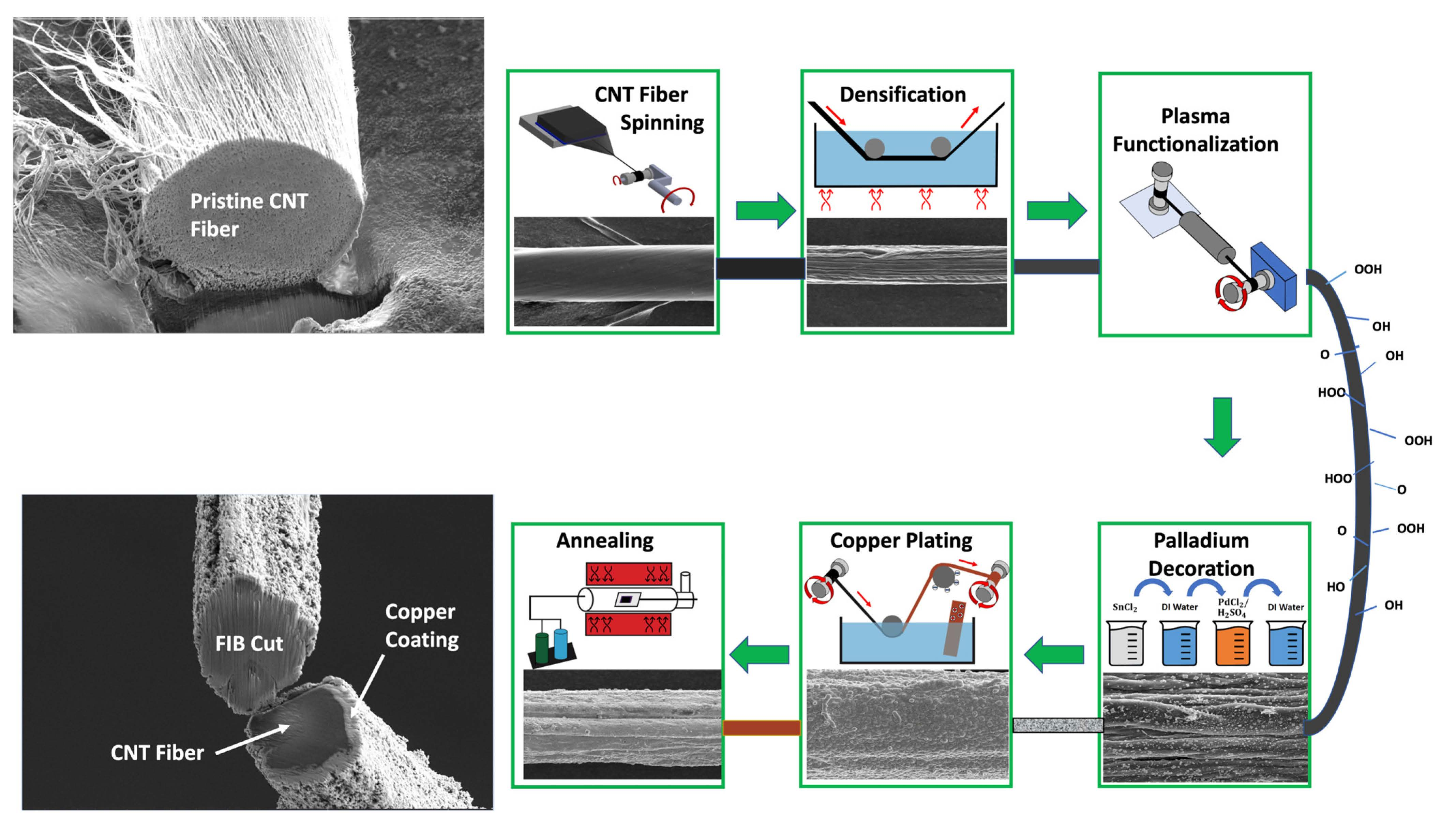
2.2. Experimental Methods

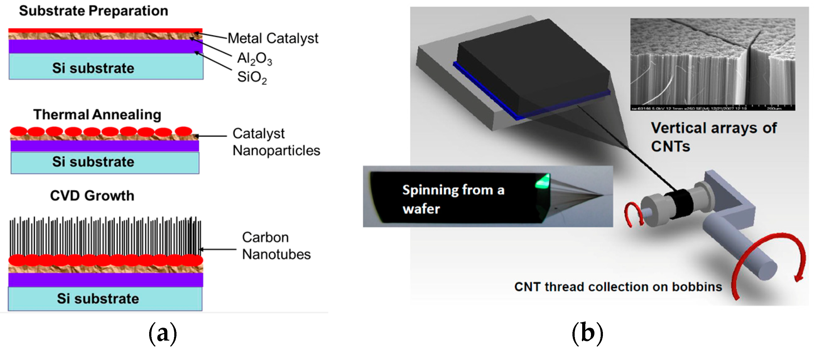
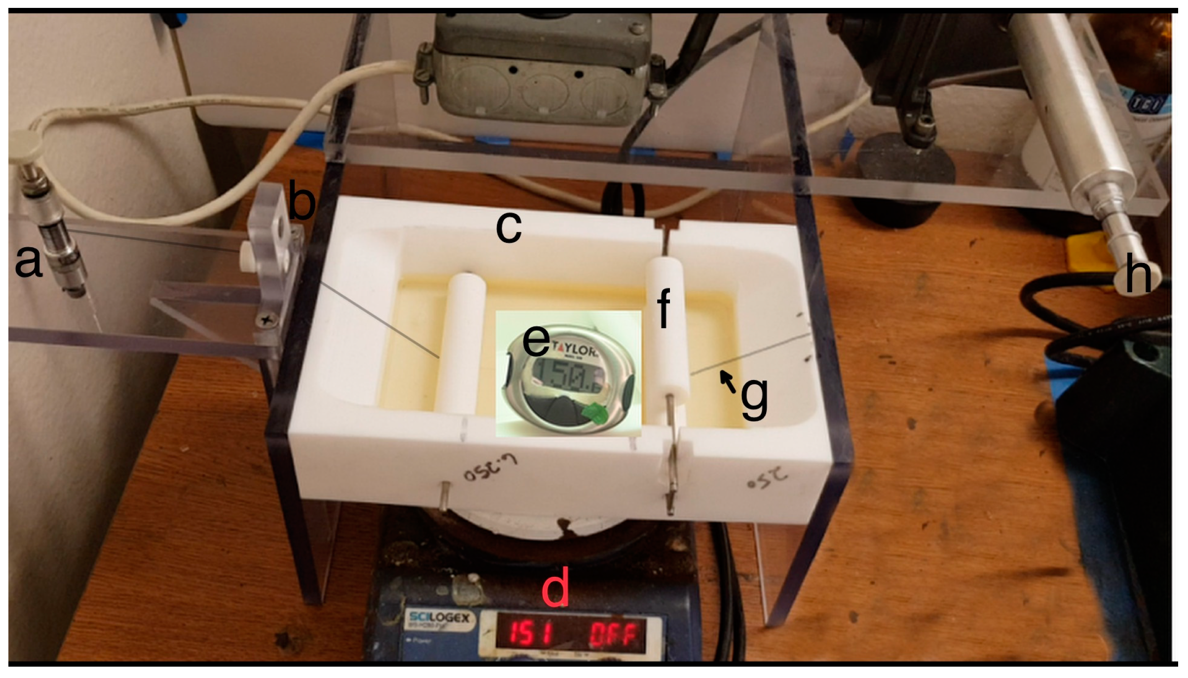
2.2.1. Dry Spinning and Densification of CNT Fiber

The CNT fiber was obtained by a dry spinning process from vertically grown CNT arrays and synthesized in-house via a chemical vapor deposition (CVD) process (Figure 1a). Oxidized silicon wafers were used as substrates with a buffer layer of Al2O3 and iron-cobalt catalyst film. The substrate was cut into (3.3 × 3.0 cm) pieces and loaded in the CVD reactor (ET 3000 model by CVD Equipment Corporation).
The synthesis process was conducted in a gas mixture of H2, C2H4, and Ar at 750 °C and atmospheric pressure. The process resulted in a vertically aligned CNT array with an average height of 300–500 µm [27,28]. The CNT array was drawn into a web by carefully pulling the array with tweezers. The spinning process was accomplished by simultaneously twisting and pulling the drawn CNT, and the spun fiber was accumulated onto a bobbin (Figure 1b). Thus, the process continued until the entire array was spun into fiber and collected on the bobbin. More details are presented in our previous publications [5,29].
The spun CNT fiber was subjected to post-treatment, which included solvent densification. Initially, this process was completed by immersing the fiber with the bobbin in acetone for 15 min, followed by air drying. However, such an approach had a major disadvantage of non-uniform densification. Therefore, a novel densification method was adopted (Figure 2).
First, the fiber from the source/feed bobbin was passed through an acrylic die hole. The stretched fiber was then fed into a hot solvent bath of multiple Teflon rods for guiding and compressing. Further, the fiber was stretched out of the bath where the solvent dried off. Finally, the densified fiber was collected onto the second bobbin. The collecting bobbin rotated on a spindle, which exerted a force on the feed bobbin, thus pulling the fiber through the hot solvent bath. The pulling speed was optimized, so the fiber did not experience any damage or breakage in the hot solvent. Pooling with the optimized speed of 0.04 m/min secured a 25 s dwelling time in the solvent. This unique densification setup and related approach allowed the fiber to undergo simultaneous hot/wet stretching and compression in N-methyl pyrrolidone (NMP) solvent. The latter is a highly polar and non-volatile substance that has been proven to enhance densification in CNT [30]. The effectiveness of NMP as a densifying solvent was demonstrated and published elsewhere [31]. The elevated temperature of 150 ± 50 °C decreased the solvent’s viscosity [32], resulting in better infiltration and promoted sufficient drying of the fiber before being collected into the bobbin.

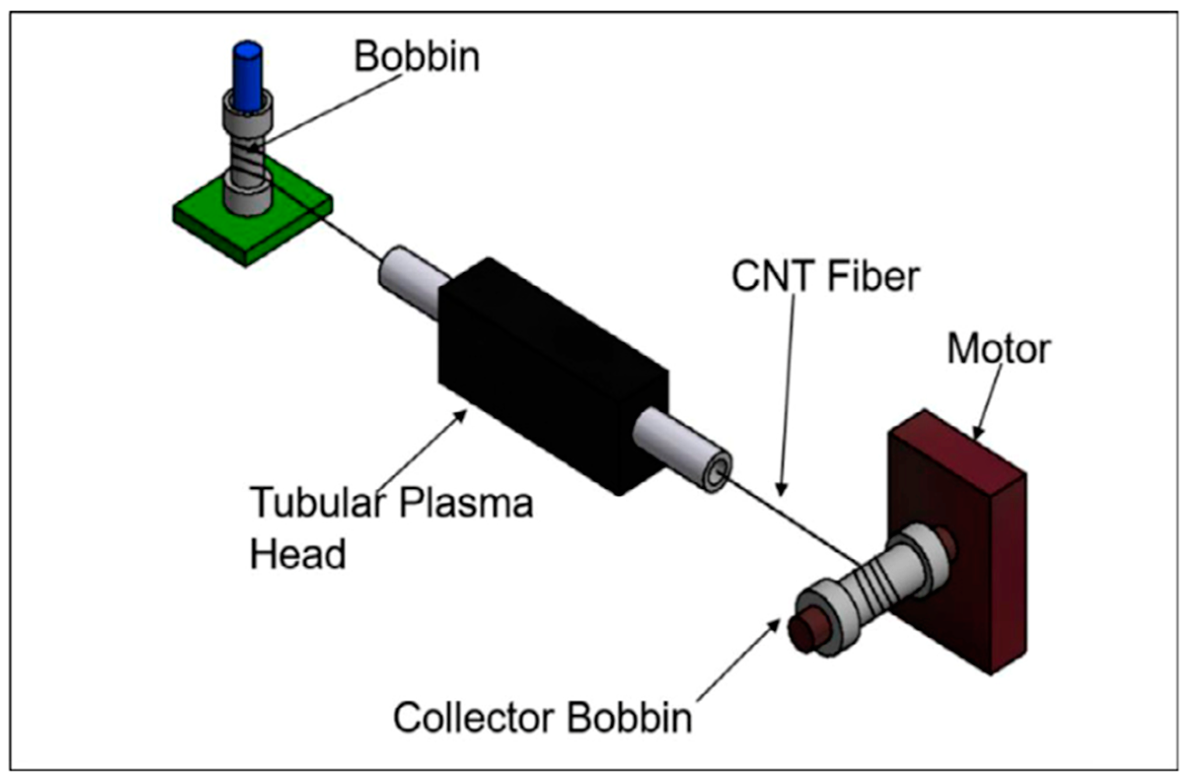
2.2.2. Continuous Oxygen Plasma Functionalization of CNT Fiber

As carbon-based materials are known to be naturally hydrophobic [33], the CNT fibers was functionalized by atmospheric-pressure helium/oxygen plasma to increase its wettability for the subsequent metal coating process. The CNT fiber wound on a feed bobbin was threaded through a tubular plasma head and then collected on a motorized collecting bobbin (Figure 3). The latter was driven by a motor applying a constant pulling speed of 17.4 cm/min on the CNT fiber through the plasma head, resulting in its uniform functionalization. The plasma settings were 100 W RF power, 0.30 L/min oxygen, and 15 L/min helium flow rates. Fibers as long as 25 m were functionalized in this manner.

2.2.3. Palladium Decoration on CNT Fiber

The oxygen-plasma-functionalized CNT fibers were decorated with palladium via electroless deposition, which involved dipping the entire fiber in Sn and Pd solutions (0.22 M stannous (II) chloride dihydrate (SnCl2·2H2O) and 0.01 M palladium (II) chloride (PdCl2 + 0.36 M H2SO4)) to enable the following reactions [35].
Sn2+ → Sn4+ + 2e
Pd2+ + 2e → Pd0
A 10-s rinse in a deionized (DI) water bath was applied after dipping in Sn and Pd. The resultant CNT fiber decorated with Pd was air-dried in an oven at 40–50 °C for 10–20 min. A simple schematic of the electroless Pd decoration process is shown in Figure S1 of the Supplementary Information (SI). The mechanism of electroless deposition is detailed in SI, Section S1.2, and Figure S2 [36]. The formed network of Pd clusters on the surface of the CNT fiber enabled the following electrodeposition of copper.

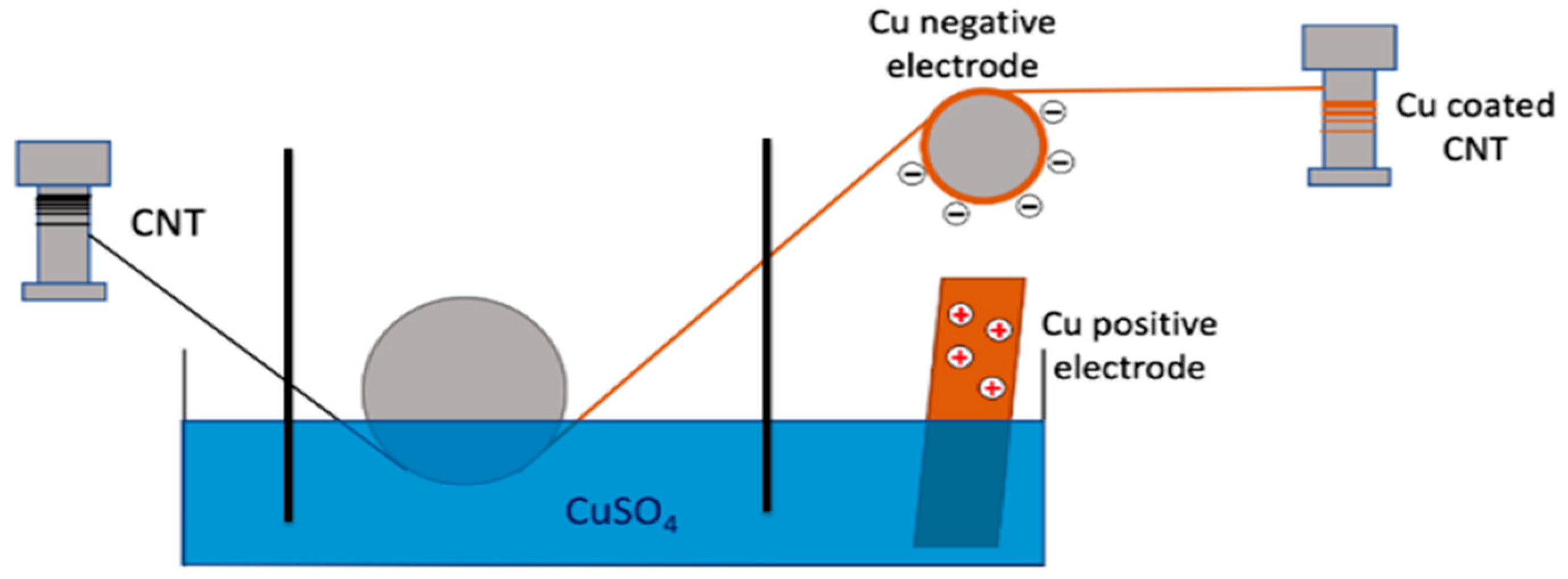
2.2.4. Continuous Electrodeposition of Copper on CNT Fiber

Copper electrodeposition was accomplished by a bobbin-to-bobbin continuous process similar to the CNT plasma functionalization (Section 2.2.3). Palladium-decorated CNT fiber was pulled from the feed bobbin onto a motorized collector bobbin through a 1 M CuSO4 electrolyte bath, where a glass rod was used to keep the fiber inside the bath. A copper electrode (99.9% pure) immersed inside the electrolyte bath was used as an anode, whereas the fiber acted as the cathode powered by a copper negative electrode. Finally, the coated fiber passed over a floating copper foil kept in front of the collector bobbin. The schematic of the continuous copper deposition setup is shown in Figure 4.
Initially, copper was electrodeposited on fibers moving at 0.174 m/min and applying a 7 V deposition voltage. However, non-uniform copper deposition across the diameter of the fiber was observed. A further improvement was achieved by introducing an initial copper seeding step at a pulling speed of 0.25 m/min, followed by the copper deposition step at a pulling speed of 0.174 m/min. The deposition voltage was maintained at 7 V for both the seeding and deposition steps. The double electrodeposition process ensured a dense and uniform copper coating on the CNT fiber.

2.2.5. Annealing of Cu–CNT Composite

The Cu–CNT composite was annealed at 450 °C to improve the morphology, uniformity, strength, and electrical conductivity. Annealing was conducted for one hour in an atmosphere of argon and hydrogen (95%:5%), respectively.

2.2.6. Characterization and Measurements

Tensile test: The tensile strength of the fibers was obtained by using a Micro Instron testing Machine, Model 5948. Each tested fiber was supported on rectangular paper specimen holders with a gauge length of 23.5 mm and fixed within pneumatic grips during testing. A strain rate of 1 mm/min was applied to obtain a stress–strain curve. Morphology and diameter measurements of the fiber were performed using a field emission scanning electron microscope (FESEM) FEI SCIOS with a dual beam. The cross-section of the densified fiber was achieved using a microtome after embedding the CNT fiber in an epoxy resin. Details of the microtome and sample preparation are given in Supplementary Information (SI) Section S3 and Figure S7 [37]. However, microtome cutting could not be employed for the copper-coated CNT cross-section as it caused debonding between copper and CNT. Hence, focused ion beam (FIB) was employed to obtain the cross-sectional view of the Cu–CNT composite and evaluate the thickness of the copper shell on the fiber. A rough cut was performed using a 30 kV and 30 nA Ga ion beam, followed by a cleaning step with the same voltage beam and a 5 nA current to obtain a clearcut cross-section. The electrical resistance of the fiber was tested using the four-probe method. The setup for this measurement consisted of a nanovoltmeter (Keithley 2182A) and a precision current source (Keithley 6220) connected to a fiber holder with four probes. A LabView program generated a plot displaying the current vs. voltage over a set range after acquiring inputs from the nanovoltmeter when current was passed through the fiber. The electrical resistance was calculated from the slope of the graph. The resistivity and further conductivity were computed based on the obtained resistance, diameter, and length of the fiber.
Current Density Measurements: The current density of the fibers was measured with a custom-built two-probe setup. The testing apparatus was constructed using vacuum-rated KF/QF flanges, pipes, and fittings. The samples were cut to lengths of 1.5–2.5 cm to fit onto copper mounting blocks and were attached by a silver paste. A roughing pump and a turbo pump were used to pump the system, thus achieving a vacuum less than 0.2 mTorr. A LabVIEW program controlled a Keithley 220 (current source) and a Keithley 182 (nanovoltmeter). A simplified block diagram of the setup is given in Figure 5. The test setup with a mounted sample after the burnout test is given in Figure S4 of the Supplementary Information. The detailed methodology of this testing is also presented in Section S2.1 of SI.

3. Results and Discussion

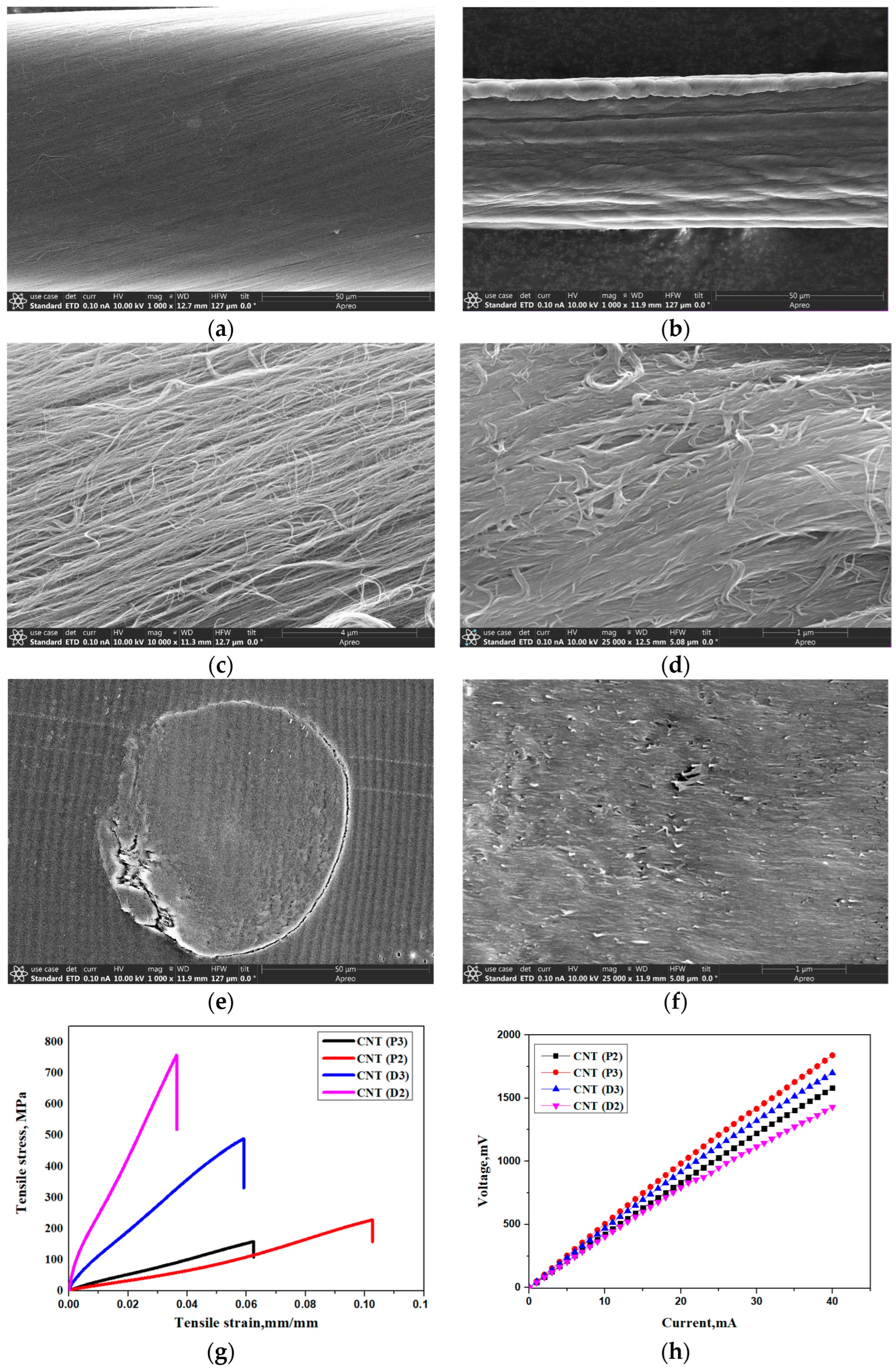
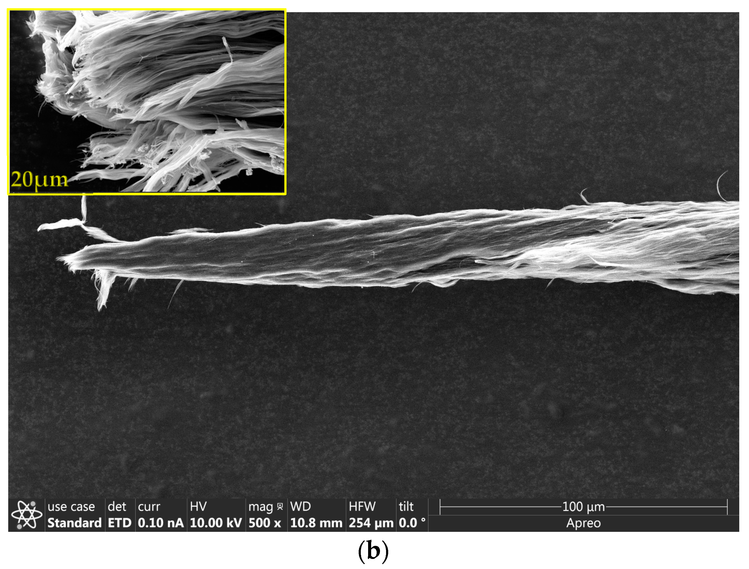
3.1. Characterization of CNT Fiber

CNT fibers of diameter 75 ± 5 µm and 95 ± 5 µm were prepared by drawing and spinning the fiber from two and three arrays, respectively. An array consisted of billions of vertically aligned CNTs per square centimeter (~1010 CNT/cm2) [27]. Each rectangular array in this work had dimensions of 3.3 cm wide × 3.0 cm long, as shown in the schematic of Table 1. The length of the CNTs within the spinnable arrays ranged between 300 and 500 µm. The average diameter of the multiwalled nanotubes was about 10–15 nm, and the spacing between them was about 70 to 100 nm. Table 1 details the CNT fibers prepared for Cu–CNT composite fabrication.
Table 1 illustrates the effect of the post-treatment on the pristine fiber. There was a 40% decrease in the diameter of the densified fiber compared to the pristine fiber. This was because the as-spun pristine fiber contained about 50% air pockets. Subjecting the pristine fiber to a densification process is a frequently used strategy, which helps to reduce the air pockets and increase the density. This resulted in an increase in both the mechanical and electrical conductivity properties [38].
The SEM images of the pristine fiber, shown in Figure 6a,c display loose bundles of nanotubes with visible air pockets. In contrast, the densified fiber in Figure 6b,d appears highly aligned and densely packed. Figure 6e,f give the cross-sectional image of densified CNT (D2). These images were obtained by cutting D2 with a microtome (Figure S7b,c). The higher magnification cross-sectional image in Figure 6f appears to be solvent-densified, with aligned CNT bundles and a lesser porosity.
The tensile strength of pristine 90 µm and 70 µm CNT fiber were 85 and 228 MPa, respectively (Figure 6g). The relatively low mechanical strength could be attributed to the fiber being a macro-scale assembly of millions of nanotubes held together by weak van der Waals forces. Unlike strong covalent sp2 hybridized bonds observed in the basic CNT hexagonal lattice structure, the weak van der Waals forces resulted in a low degree of contact bonding between the tubes, which made the pristine fibers mechanically frail. In contrast, the densified fiber showed more than a 200% increase in the mechanical strength (Figure 6g) and 170% (Figure 6h) increase in the conductivity after the densification process. This increase could be attributed to the better alignment of CNT bundles [26], resulting in a higher packing density. Similar densification attempts from our group earlier also reported an increase in the density by two times with a tenfold decrease in the porosity [29]. The lower strength of the higher-diameter fiber could be due to a comparatively greater non-uniformity in the spun fiber with respect to the fiber alignment and diameter along the fiber length, and also because of the incomplete densification within the entire cross-section of the fiber with the enlarged diameter.

3.2. Characterization of the Coated CNT Fiber

3.2.1. Effect of Plasma Functionalization

The densified CNT fiber of 45 ± 5 µm proved superior among the characterized fibers with respect to the mechanical strength and electrical conductivity. It hence was used as the core for Cu–CNT core–shell composite fiber. The densified fiber was further functionalized by atmospheric pressure He/O2 plasma to introduce oxygen groups such as hydroxyl (-OH), carbonyl (-C=O-), and carboxyl (-C=O-O-) groups. This procedure increased the oxygen content from 9.1% in the pristine fiber to 27.5% in the functionalized fiber. The data were obtained from the XPS analysis conducted in our earlier work after the functionalization of the same type of CNT fiber [34]. Furthermore, oxygen plasma functionalization effectively enhances the hydrophilicity of CNT and other nano carbons, as demonstrated in our recent publications [39,40]. The imposed hydrophilicity facilitated better interactions of CNT with the coated metal particles, thus improving their adhesion for fabricating high-performance composites.

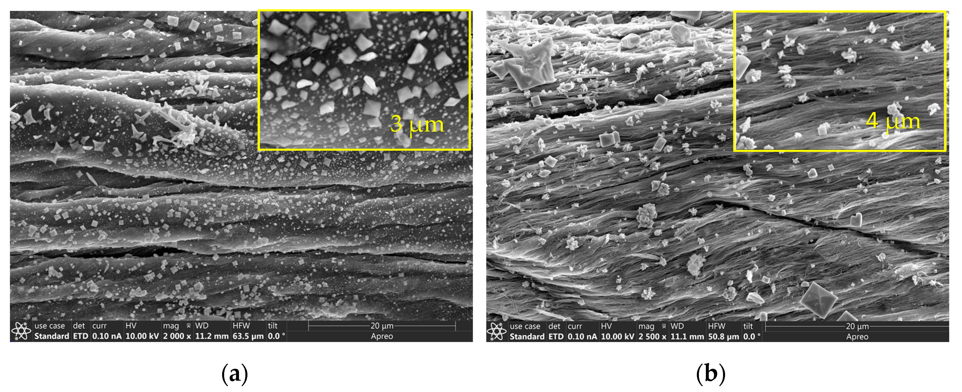
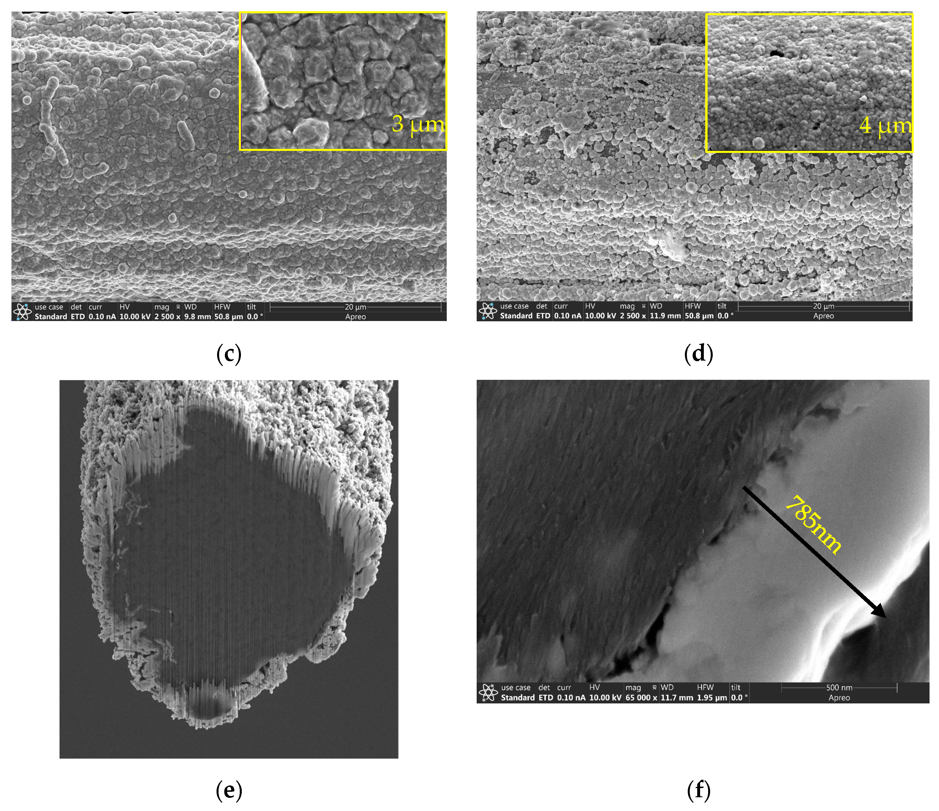
3.2.2. Morphological Characterization of the Metal-Coated CNT Fiber

The SEM image of palladium-decorated CNT is displayed in Figure 7a. This figure confirms the uniform coating of palladium nanoparticles on the oxygen plasma functionalized CNT fiber surface. The palladium particles, which acted as catalyst sites for the nucleation and growth of copper metal, ensured a uniform layer of copper deposited over it, as can be seen in Figure 7b after the copper seeding process. This first layer of copper appeared to be a thin film over the palladium particles. The surface feature of the CNT substrate with Pd determined the grain structure of the first layer of copper. However, during the formation of the second layer over time, as the coating thickened, the grain structure was determined mainly by the bath composition, electrodeposition parameters, and dwell time.
Figure 7c reveals the morphology of the second layer of copper over the first seeding. The second layer of copper appeared dense and uniform. The pre-addition of Pd and seed Cu layers helped prevent excess or insufficient deposition of the second layer of copper. The copper layer had a comparatively coarse surface and large faceted crystallites. However, after annealing at a temperature of 450 °C, the morphology of the copper-coated CNT had a smooth and uniform surface with a larger crystallite size (Figure 7d). The EDS of the Pd-coated Cu–CNT, is given in Figure S3. Figure 7e,f provides the cross-sectional view of the Cu–CNT composite obtained by FIB. The average copper thickness was measured to be slightly less than 1 µm, and the polycrystalline copper was observed to be tightly bound with the CNT fiber.

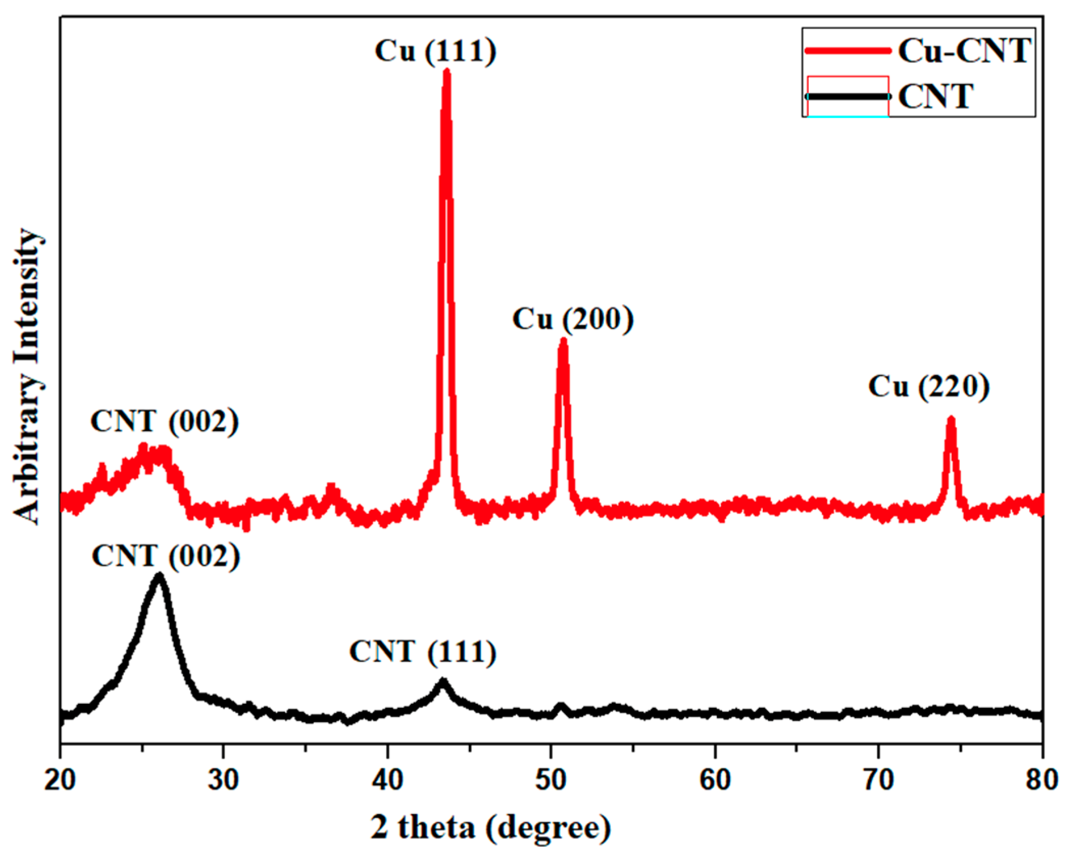
3.2.3. X-ray Diffraction of Cu–CNT Composite

X-ray Diffraction (XRD) study confirmed the crystal orientation of the composite. Figure 8 compares the X-ray diffraction pattern of a copper-coated CNT fiber with an uncoated one. From the XRD patterns of pristine CNT, the most pronounced peak was observed at 2θ = 26 degrees, representing the reflection of graphite arising due to the tubular structure of the carbon atoms in the sample with (002) plane orientation [41], which appeared weak in the Cu–CNT fiber due to copper cladding. The strong diffraction peaks of copper probably covered the weak signals of CNTs, resulting in the reduced intensity [42].
The XRD pattern of the Cu–CNT fiber unraveled the characteristic peaks of (111), (200), and (220) at 2θ = 43°, 50°, and 74.1°, respectively, revealing the face-centered cubic (FCC) crystal structure of copper. We also observed that the peak intensity of (111), the closest packed peak in the FCC structure [43], was dominant compared to other peaks. This indicates texturing of the copper layer with growth in the (111) direction during the electroplating process. The crystallite size was calculated using the Scherrer equation given by Dp = (0.94 λ)/(βcosθ), where Dp is the average crystallite size, λ is the wavelength of the X-ray, β is the line full width at half maximum (FWHM) intensity of the diffraction profile, and θ is the Braggs angle [44]. The crystallite size of the copper in the (111) orientation was calculated to be 15 nm, and for CNT, it was 2 nm along the (002) orientation. Copper grown via electroplating shows certain imperfections, confirmed by a high porosity, polycrystallinity, and small grain size [44]. The CNT crystallite size is in agreement with the literature data for dry-spun multi-walled CNTs synthesized by the CVD process [45,46].

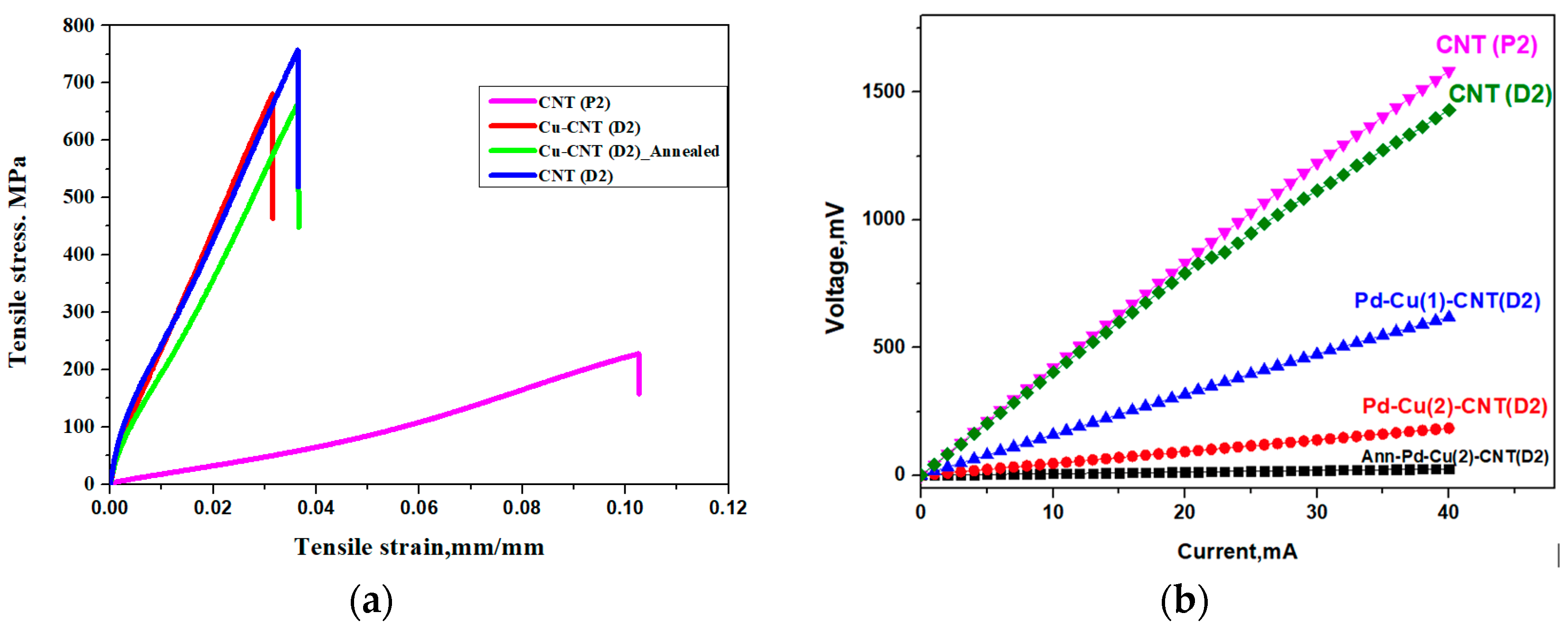
3.2.4. Mechanical and Electrical Properties

From Figure 9a, it can be found that the pristine CNT had a tensile strength of 228 MPa, whereas post-treated CNT fiber D2(CNT) showed a tensile strength of 757 MPa. However, the tensile strength of a typical copper wire is comparatively low: 210 MPa [47]. The Cu–CNT composite revealed a higher mechanical strength (681 MPa, Figure 9a) than commercial copper wire, owing to the high tensile strength of the core CNT fiber.
This greater mechanical strength could be attributed to the fiber post-treatment and better Cu–CNT interaction accomplished by the CNT fiber functionalization and Pd-based electroless deposition. On the other hand, the annealed Cu–CNT composite showed a decreased tensile strength (665 MPa) compared to the unannealed composite, indicating the annealing process had rendered the composite more brittle and, in some cases, partly oxidized.
The electrical conductivity of the fiber was measured by the four-probe method. The extended length of the fiber used was 5 mm, and it provided a more accurate measurement as the current and voltage terminals were separated to avoid contact resistance. Figure 9b,c illustrate the comparison of the I–V plot and electrical conductivity values between the tested samples. The post-treated CNT (D2(CNT)) fiber revealed a 170% increase in the electrical conductivity as compared to pristine fiber P2 (CNT). This proved that the core was highly aligned and densely packed, thus facilitating good conductivity. The electrical conductivity of the fiber, double-coated with copper (Pd–Cu (2) CNT) fiber, drastically increased by an order. After annealing, the sample Ann-Pd–Cu (2) CNT showed a further increase in the conductivity by 66% due to the surface smoothening and replacement of the coarse grain structure by a smooth and uniform microstructure.

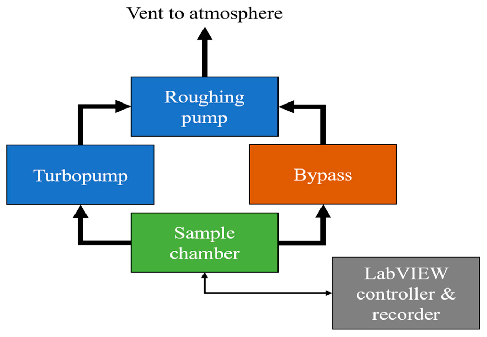
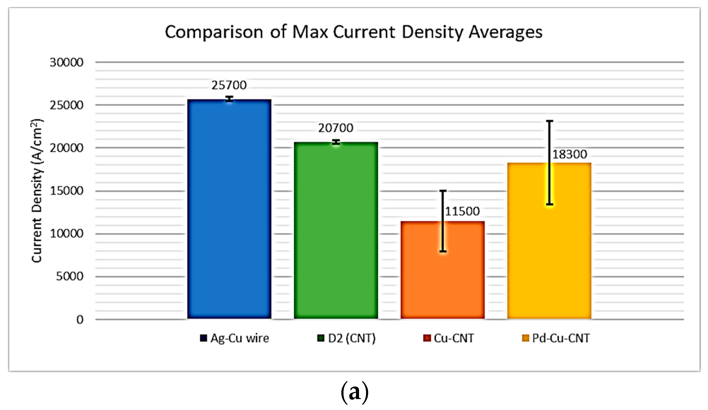
3.2.5. Current Density Measurements

Ampacity or current density can be defined as the maximum current a wire can carry divided by its cross-section [48]. Figure 10a gives the comparative ampacity values between the tested samples.
Copper is a commonly used reference or standard with a current density between 97,000 A/cm2 [49] and 106 A/cm2 [48]. In this work, a silver-clad copper wire (60 μm diameter) was tested as a reference point. It was found to have a maximum current density of 25,700 A/cm2. The uncoated CNT sample (post-treated) exhibited superior current density value yielding an average maximum current density of 20,700 A/cm2 compared to copper-coated CNT composites. The Cu–CNT and Pd–Cu–CNT samples had an average maximum current density of 11,500 ± 3540 A/cm2 and 18,300 ± 4870 A/cm2, respectively. The CNT fiber revealed superior value due to its strong C-C covalent bond within the tubes, tight packing, and good alignment compared to copper. In addition, the electrical conductivity of CNTs tends to increase with a rising temperature, which may explain this trend [50].
The composite samples with electroless palladium decoration (Pd–Cu–CNT) outperformed those without Pd decoration (Cu–CNT). This confirmed the positive effect of palladium coating, which activated the CNT surface for more uniform Cu coating and stronger bonding between the copper and CNT.
However, the ampacity of the core–shell copper–CNT composite appeared lower than expected, which could be attributed to the following reason. Copper is highly conductive with a denser structure and fewer imperfections, which helps the flow of electrons in the direction of the electric field, suppressing the effect of Joule heating. However, the copper in the core–shell composite had a higher resistance and lower conductivity and current density, resulting in more pronounced Joule heating leading to a poor thermal exchange with the surrounding environment [2].
The burnout sample after the current density measurement was observed by SEM (Figure 10b). It revealed no remaining copper coating, which EDS confirmed (Figure S5). The copper coating likely sublimed or evaporated from the surface of the composite fiber due to the intense Joule heating and vacuum environment [51,52]. The Joule effect in the samples is further discussed in the SI, Section S2.4.

4. Conclusions and Future Perspective

This work presents a scalable method for fabricating a lightweight copper–CNT core–shell fiber composite with a mechanical strength three times greater than commercial copper, along with good electrical conductivity and ampacity. The positive effect of atmospheric oxygen plasma functionalization and the palladium decoration of the CNT fiber on the following electrochemical deposition of copper and its improved morphology and adhesion to the CNT fiber was demonstrated. Furthermore, a reliable experimental setup for measuring the current density was designed and fabricated, which allowed the ampacity characterization of different composite fibers. From a future perspective, incorporating copper within the CNT fiber core, rather than cladding it on the outside as a shell, would enhance the electrical properties and yield longer-life composites, as the copper sublimation/evaporation rate could be reduced. In addition, such an internal loading could replace any internal voids or porosity in the composite with copper, which will offer a better use of the composite’s volume, also leading to increased ampacity.

Supplementary Materials

The following supporting information can be downloaded at: https://www.mdpi.com/article/10.3390/c9020043/s1. Figure S1: Schematic of palladium decoration on CNT by electroless deposition; Figure S2: Mechanism of Pd electroless deposition; Figure S3: EDS of Pd–Cu–CNT fiber; Figure S4: CNT sample after burnout on a current density measurement setup; Figure S5: EDS of burnout sample after current density test; Figure S6: Examples of hysteresis seen in voltage-current plots; Figure S7: Schematic and pictures of cutting by microtome.

Author Contributions

Conceptualization: M.L., V.S. and D.M.; methodology: V.S. and D.M.; validation: V.S., D.M., M.L., A.S.A. and D.S.; characterization and investigation: K.M.J., K.B., V.K.R.K., M.K., A.A.R., B.D.K., H.J.K., N.P. and A.K.; resources: V.S. and D.M.; data curation: K.M.J.; writing—original draft preparation: K.M.J., K.B., V.K.R.K., M.K., A.A.R., B.D.K., H.J.K. and A.K.; writing—review and editing: V.S., A.S.A., M.L. and D.S.; supervision: V.S., D.M., A.S.A., D.S. and M.L.; project administration, V.S. and M.L.; funding acquisition, V.S. and M.L. All authors have read and agreed to the published version of the manuscript.

Funding

The research was funded by NASA through a grant # NASA 80NSSC21P2821.

Data Availability Statement

Data is available upon request.

Conflicts of Interest

The authors declare no conflict of interest.

References

  1. Tran, T.Q.; Lee, J.K.Y.; Chinnappan, A.; Jayathilaka WA, D.M.; Ji, D.; Kumar, V.V.; Ramakrishna, S. Strong, lightweight, and highly conductive CNT/Au/Cu wires from sputtering and electroplating methods. J. Mater. Sci. Technol. 2020, 40, 99–106. [Google Scholar] [CrossRef]
  2. Daneshvar, F.; Chen, H.; Zhang, T.; Sue, H.J. Fabrication of Light-Weight and Highly Conductive Copper–Carbon Nanotube Core–Shell Fibers through Interface Design. Adv. Mater. Interfaces 2020, 7, 2000779. [Google Scholar] [CrossRef]
  3. Almansour, A.; Sacksteder, D.; Goretski, A.J.; Lizcano, M. Novel processing, testing and characterization of copper/carbon nanotube (Cu/CNT) yarn composite conductor. Int. J. Appl. Ceram. Technol. 2023, 20, 917–937. [Google Scholar] [CrossRef]
  4. de Groh, H.C. Highly Conductive Wire: Cu-Carbon Nanotube Composite Ampacity and Metallic CNT Buckypaper Conductivity. MRS Adv. 2017, 2, 71–76. [Google Scholar] [CrossRef]
  5. Alvarez, N.T.; Miller, P.; Haase, M.; Kienzle, N.; Zhang, L.; Schulz, M.J.; Shanov, V. Carbon nanotube assembly at near-industrial natural-fiber spinning rates. Carbon 2015, 86, 350–357. [Google Scholar] [CrossRef]
  6. Zhang, X.; Li, Q.; Holesinger, T.G.; Arendt, P.N.; Huang, J.; Kirven, P.D.; Clapp, T.G.; Depaula, R.F.; Liao, X.; Zhao, Y.; et al. Ultrastrong, stiff, and lightweight carbon-nanotube fibers. Adv. Mater. 2007, 19, 4198–4201. [Google Scholar] [CrossRef]
  7. Behabtu, N.; Green, M.J.; Pasquali, M. Carbon nanotube-based neat fibers. Nano Today 2008, 3, 24–34. [Google Scholar] [CrossRef]
  8. Chen, S.; Qiu, L.; Cheng, H.M. Carbon-Based Fibers for Advanced Electrochemical Energy Storage Devices. Chem. Rev. 2020, 120, 2811–2878. [Google Scholar] [CrossRef]
  9. Tran, T.Q.; Fan, Z.; Liu, P.; Myint, S.M.; Duong, H.M. Super-strong and highly conductive carbon nanotube ribbons from post-treatment methods. Carbon 2016, 99, 407–415. [Google Scholar] [CrossRef]
  10. Jung, Y.; Cho, Y.S.; Lee, J.W.; Oh, J.Y.; Park, C.R. How can we make carbon nanotube yarn stronger? Compos. Sci. Technol. 2018, 166, 95–108. [Google Scholar] [CrossRef]
  11. Qiu, L.; Wang, X.; Tang, D.; Zheng, X.; Norris, P.M.; Wen, D.; Zhao, J.; Zhang, X.; Li, Q. Functionalization and densification of inter-bundle interfaces for improvement in electrical and thermal transport of carbon nanotube fibers. Carbon 2016, 105, 248–259. [Google Scholar] [CrossRef]
  12. Hannula, P.-M.; Peltonen, A.; Aromaa, J.; Janas, D.; Lundström, M.; Wilson, B.P.; Koziol, K.; Forsén, O. Carbon nanotube-copper composites by electrodeposition on carbon nanotube fibers. Carbon 2016, 107, 281–287. [Google Scholar] [CrossRef]
  13. Han, B.; Guo, E.; Xue, X.; Zhao, Z.; Luo, L.; Qu, H.; Niu, T.; Xu, Y.; Hou, H. Fabrication and densification of high performance carbon nanotube/copper composite fibers. Carbon 2017, 123, 593–604. [Google Scholar] [CrossRef]
  14. Kim, Y.K.; Kim, Y.J.; Park, J.; Han, S.W.; Kim, S.M. Purification effect of carbon nanotube fibers on their surface modification to develop a high-performance and multifunctional nanocomposite fiber. Carbon 2021, 173, 376–383. [Google Scholar] [CrossRef]
  15. Milowska, K.Z.; Burda, M.; Wolanicka, L.; Bristowe, P.D.; Koziol, K.K.K. Carbon nanotube functionalization as a route to enhancing the electrical and mechanical properties of Cu-CNT composites. Nanoscale 2019, 11, 145–157. [Google Scholar] [CrossRef]
  16. Xu, G.; Zhao, J.; Li, S.; Zhang, X.; Yong, Z.; Li, Q. Continuous electrodeposition for lightweight, highly conducting and strong carbon nanotube-copper composite fibers. Nanoscale 2011, 3, 4215–4219. [Google Scholar] [CrossRef]
  17. Wright, K.D.; Gowenlock, C.E.; Bear, J.C.; Barron, A.R. Understanding the Effect of Functional Groups on the Seeded Growth of Copper on Carbon Nanotubes for Optimizing Electrical Transmission. ACS Appl. Mater. Interfaces 2017, 9, 27202–27212. [Google Scholar] [CrossRef]
  18. Liu, Y.; Tao, J.; Liu, Y.; Hu, Y.; Bao, R.; Li, F.; Fang, D.; Li, C.; Yi, J. Regulating the mechanical properties and electrical conductivity of CNTs/Cu composites by tailoring nano-sized TiC on the surface of intact CNTs. Carbon 2021, 185, 428–441. [Google Scholar] [CrossRef]
  19. Zou, J.; Liu, D.; Zhao, J.; Hou, L.; Liu, T.; Zhang, X.; Zhao, Y.; Zhu, Y.T.; Li, Q.; Light-Weight, N.N.L.P. Ni Nanobuffer Layer Provides Light-Weight CNT/Cu Fibers with Superior Robustness, Conductivity, and Ampacity. ACS Appl. Mater. Interfaces 2018, 10, 8197–8204. [Google Scholar] [CrossRef]
  20. Milowska, K.Z.; Ghorbani-Asl, M.; Burda, M.; Wolanicka, L.; Ćatić, N.; Bristowe, P.D.; Koziol, K.K. Breaking the electrical barrier between copper and carbon nanotubes. Nanoscale 2017, 9, 8458–8469. [Google Scholar] [CrossRef]
  21. Rodrigues, F.; Pinheiro, P.; Sousa, M.; Angélica, R.; Paz, S.; Reis, M. Electrical Properties of Iodine-Doped Cu/f-CNT Coated Aluminum Wires by Electrophoresis with Copper Sulfate Solution. Metals 2022, 12, 787. [Google Scholar] [CrossRef]
  22. Chen, H.; Daneshvar, F.; Tu, Q.; Sue, H.J. Highly Conductive and Ultra-Strong Carbon Nanotube-Copper Core-Shell Wires as High-Performance Power Transmission Cables. ACS Chem. Life 2022. [Google Scholar] [CrossRef]
  23. Han, B.; Guo, E.; Xue, X.; Zhao, Z.; Li, T.; Xu, Y.; Luo, L.; Hou, H. Fabricating and strengthening the carbon nanotube/copper composite fibers with high strength and high electrical conductivity. Appl. Surf. Sci. 2018, 441, 984–992. [Google Scholar] [CrossRef]
  24. Sundaram, R.; Yamada, T.; Hata, K.; Sekiguchi, A. Electrical performance of lightweight CNT-Cu composite wires impacted by surface and internal Cu spatial distribution. Sci. Rep. 2017, 7, 3241–3249. [Google Scholar] [CrossRef]
  25. Alvarez, N.T.; Ochmann, T.; Kienzle, N.; Ruff, B.; Haase, M.R.; Hopkins, T.; Pixley, S.; Mast, D.; Schulz, M.J.; Shanov, V. Polymer coating of carbon nanotube fibers for electric microcables. Nanomaterials 2014, 4, 879–893. [Google Scholar] [CrossRef]
  26. Jayasinghe, C. Synthesis and Characterization of Carbon Nanotube, Threads, Yarns, and Sheets. Ph.D. Thesis, University of Cincinnati, Cincinnati, OH, USA, 2011. [Google Scholar]
  27. Shanov, V.; Cho, W.; Malik, R.; Alvarez, N.; Haase, M.; Ruff, B.; Kienzle, N.; Ochmann, T.; Mast, D.; Schulz, M. CVD growth, characterization and applications of carbon nanostructured materials. Surf. Coat. Technol. 2013, 230, 77–86. [Google Scholar] [CrossRef]
  28. Cho, W.; Schulz, M.; Shanov, V. Growth and characterization of vertically aligned centimeter long CNT arrays. Carbon 2014, 72, 264–273. [Google Scholar] [CrossRef]
  29. Shanov, V.N.; Schulz, M.J. Methods of Growing Carbon Nanotubes and Carbon Nanotube Thread. U.S. Spinning Patent 9,796,121(b2), 24 October 2017. [Google Scholar]
  30. Li, S.; Zhang, X.; Zhao, J.; Meng, F.; Xu, G.; Yong, Z.; Jia, J.; Zhang, Z.; Li, Q. Enhancement of carbon nanotube fibres using different solvents and polymers. Compos. Sci. Technol. 2012, 72, 1402–1407. [Google Scholar] [CrossRef]
  31. Kanakaraj, S.N.; Alvarez, N.T.; Gbordzoe, S.; Lucas, M.S.; Maruyama, B.; Noga, R.; Hsieh, Y.Y.; Shanov, V. Improved dry spinning process at elevated temperatures for making uniform and high strength CNT fibers. Mater. Res. Express 2018, 5, 065036. [Google Scholar] [CrossRef]
  32. Langan, J.R.; Salmon, G.A. Physical Properties of N methylpryrrolidinine as function of temperature. J. Chem. Eng. Data 1987, 32, 420–422. [Google Scholar] [CrossRef]
  33. Malik, R.; McConnell, C.; Alvarez, N.T.; Haase, M.; Gbordzoe, S.; Shanov, V. Rapid, in situ plasma functionalization of carbon nanotubes for improved CNT/epoxy composites. RSC Adv. 2016, 6, 108840–108850. [Google Scholar] [CrossRef]
  34. Adusei, P.K.; Gbordzoe, S.; Kanakaraj, S.N.; Hsieh, Y.Y.; Alvarez, N.T.; Fang, Y.; Johnson, K.; McConnell, C.; Shanov, V. Fabrication and study of supercapacitor electrodes based on oxygen plasma functionalized carbon nanotube fibers. J. Energy Chem. 2020, 40, 120–131. [Google Scholar] [CrossRef]
  35. McConnell, C.; Kanakaraj, S.N.; Dugre, J.; Malik, R.; Zhang, G.; Haase, M.R.; Hsieh, Y.Y.; Fang, Y.; Mast, D.; Shanov, V. Hydrogen Sensors Based on Flexible Carbon Nanotube-Palladium Composite Sheets Integrated with Ripstop Fabric. ACS Omega 2020, 5, 487–497. [Google Scholar] [CrossRef] [PubMed]
  36. Ang, L.M.; Hor, T.S.A.; Xu, G.Q.; Tung, C.H.; Zhao, S.P.; Wang, J.L.S. Decoration of activated carbon nanotubes with copper and nickel. Carbon 2000, 38, 363–372. [Google Scholar] [CrossRef]
  37. Gupta, P.; Rahm, C.E.; Griesmer, B.; Alvarez, N.T. Carbon Nanotube Microelectrode Set: Detection of Biomolecules to Heavy Metals. Anal. Chem. 2021, 93, 7439–7448. [Google Scholar] [CrossRef]
  38. Sears, K.; Skourtis, C.; Atkinson, K.; Finn, N.; Humphries, W. Focused ion beam milling of carbon nanotube yarns to study the relationship between structure and strength. Carbon 2010, 48, 4450–4456. [Google Scholar] [CrossRef]
  39. Joseph, K.M.; Kasparian, H.J.; Shanov, V. Carbon Nanotube Fiber-Based Wearable Supercapacitors—A Review on Recent Advances. Energies 2022, 15, 6506. [Google Scholar] [CrossRef]
  40. Joseph, K.M.; Shanov, V. Symmetric Supercapacitor Based on Nitrogen-Doped and Plasma-Functionalized 3D Graphene. Batteries 2022, 8, 258. [Google Scholar] [CrossRef]
  41. Peng, Y.; Chen, Q. The synthesis of a copper/multi-walled carbon nanotube hybrid nanowire in a microfluidic reactor. Nanotechnology 2009, 20, 235606. [Google Scholar] [CrossRef]
  42. Chen, S.; Fu, S.; Liang, D.; Chen, X.; Mi, X.; Liu, P.; Zhang, Y.; Hui, D. Preparation and properties of 3D interconnected CNTs/Cu composites. Nanotechnol. Rev. 2020, 9, 146–154. [Google Scholar] [CrossRef]
  43. Lin, C.-T.; Lin, K.-L. Effects of current density and deposition time on electrical resistivity of electroplated Cu layers. Mater. Electron. 2004, 15, 757–762. [Google Scholar] [CrossRef]
  44. Yu, S.; Park, B.I.; Park, C.; Hong, S.M.; Han, T.H.; Koo, C.M. RTA-treated carbon fiber/copper core/shell hybrid for thermally conductive composites. ACS Appl. Mater. Interfaces 2014, 6, 7498–7503. [Google Scholar] [CrossRef] [PubMed]
  45. Kumar, D.; Singh, K.; Verma, V.; Bhatti, H.S. Low-temperature hydrothermal synthesis and functionalization of multiwalled carbon nanotubes. Indian J. Phys. 2016, 90, 139–148. [Google Scholar] [CrossRef]
  46. Zhang, S.; Zhu, L.; Minus, M.L.; Chae, H.G.; Jagannathan, S.; Wong, C.P.; Kowalik, J.; Roberson, L.B.; Kumar, S. Solid-state spun fibers and yarns from 1-mm long carbon nanotube forests synthesized by water-assisted chemical vapor deposition. J. Mater. Sci. 2008, 43, 4356–4362. [Google Scholar] [CrossRef]
  47. Available online: https://www.matweb.com/search/datasheet_print.aspx?matguid=9aebe83845c04c1db5126fada6f76f7e (accessed on 6 February 2023).
  48. Subramaniam, C.; Yamada, T.; Kobashi, K.; Sekigushi AFutaba, D.N.; Yumura, M.; Hata, K. One hundred fold increase in current carrying capacity in a carbon nanotube-copper composite. Nat. Commun. 2013, 4, 2202. [Google Scholar] [CrossRef]
  49. Liu, D.; Wang, P.; Zhang, X.; Chen, C.; Zou, J.; Hou, L.; Zhao, J.; Xue, J.; Ding, F.; Gao, Z.; et al. Synergistically improved mechanical, thermal, and ampacity performances of carbon nanotube/copper composite conductors based on network confinement effects. Carbon 2023, 201, 837–846. [Google Scholar] [CrossRef]
  50. Jia, Y.; Yang, J.; Wang, K.; Chowdhury, M.A.; Chen, B.; Su, Y.; Nickerson, B.C.; Xu, C. Aligned carbon nanotube/carbon (CNT/C) composites with exceptionally high electrical conductivity at elevated temperature to 400 °C. Mater. Res. Express 2019, 6, 116302. [Google Scholar] [CrossRef]
  51. Greenwood, H.C.; Rutherford, E. The influence of Pressure on the Boiling Points of Metals. Proc. R. Soc. Lond. A 1910, 83, 483–491. [Google Scholar] [CrossRef]
  52. Kaye, G.W.; Ewen, D. The sublimation of metals at low pressures. Proc. R. Soc. Lond. A 1913, 89, 58–67. [Google Scholar] [CrossRef]
Figure 1. Schematic of CNT array synthesis and CNT fiber spinning process. (a) Growth of vertically aligned CNT array on a catalyst-sputtered substrate by CVD process. (b) Spinning of CNT fiber from the vertically aligned CNT array by pulling and twisting. Reproduced with permission from [25,26].
Carbon 09 00043 g001
Figure 2. Densification setup. (a) Supply bobbin. (b) Acrylic die hole. (c) Solvent bath. (d) Hot plate. (e) Thermometer. (f) Teflon rods. (g) CNT fiber. (h) Collecting bobbin.
Carbon 09 00043 g002
Figure 3. Schematic of continuous oxygen functionalization process by tubular plasma head setup. (Reproduced with permission from [34]).
Carbon 09 00043 g003
Figure 4. Schematic for continuous copper electrodeposition on CNT fiber.
Carbon 09 00043 g004
Figure 5. Simplified block diagram of current density testing setup.
Carbon 09 00043 g005
Figure 6. Characterization of CNT fiber. (ad) SEM images of pristine and densified fiber at different magnifications. (e) Cross-sectional SEM image of densified CNT fiber at (e) low magnification and (f) high magnification. (g) Mechanical stress–strain plots of CNT fibers. (h) I–V plots of CNT fibers obtained with four-probe measurements.
Carbon 09 00043 g006
Figure 7. Morphology (SEM images) of metal-coated CNT fiber with higher magnification images in the inset. (a) Pd–CNT fiber. (b) Pd–CNT–Cu (1st coated layer). (c) Pd–CNT–Cu (2nd coated layer). (d) Annealed Pd–CNT–Cu fiber. (e) FIB of Cu–CNT fiber at low and (f) high magnification showing the thickness of the coated copper shell.
Carbon 09 00043 g007aCarbon 09 00043 g007b
Figure 8. XRD of pristine CNT and Cu–CNT composite.
Carbon 09 00043 g008
Figure 9. Mechanical (a), electrical (b), and (c) property comparison between pristine CNT, densified CNT, copper-coated CNT, and annealed copper-coated CNT fibers.
Carbon 09 00043 g009aCarbon 09 00043 g009b
Figure 10. (a) Comparison of the average current density for various samples. (b) SEM image of the burnout sample. (Inset high magnification image).
Carbon 09 00043 g010aCarbon 09 00043 g010b
Table 1. Types of CNT Fibers Prepared for Cu–CNT Composite Fabrication.
Number of ArraysSchematic Type of FiberDiameter, µm
TwoCarbon 09 00043 i001Pristine (P2)

Densified (D2)
75 ± 5

45 ± 5
ThreeCarbon 09 00043 i002Pristine (P3)

Densified (D3)
95± 5

55 ± 5
Disclaimer/Publisher’s Note: The statements, opinions and data contained in all publications are solely those of the individual author(s) and contributor(s) and not of MDPI and/or the editor(s). MDPI and/or the editor(s) disclaim responsibility for any injury to people or property resulting from any ideas, methods, instructions or products referred to in the content.

