Article

Influence of Carbon Nanotube Attributes on Carbon Nanotube/Cu Composite Electrical Performances

CNT-Application Research Center, National Institute of Advanced Industrial Science and Technology, Central 5, 1-1-1 Higashi, Tsukuba 3058565, Japan
*
Authors to whom correspondence should be addressed.
Submission received: 2 October 2021 / Revised: 1 November 2021 / Accepted: 5 November 2021 / Published: 15 November 2021

Abstract

:
Carbon nanotube (CNT)/copper composites offer promise as lightweight temperature-stable electrical conductors for future electrical and electronic devices substituting copper. However, clarifying how constituent nanotube structures influence CNT/Cu electrical performances has remained a major research challenge. Here, we investigate the correlation between the CNT/Cu electrical performances and nanotube structure by preparing and characterizing composites containing nanotubes of different structural attributes. We prepared three types of composites—single-wall (SW)-CNT/Cu wires, SW-CNT/Cu pillars, and multi-wall (MW)-CNT/Cu wires. The composites were fabricated from the corresponding CNT templates by two-step Cu electrodeposition, which retains template nanotube attributes through the fabrication process. The nanotube characteristics (diameter, G/D, alignment, etc.) in each template as well as the internal structure and electrical performances of the corresponding composites were characterized. SW-CNT/Cu wires and pillars outperformed MW-CNT/Cu wires, showing ≈ 3× higher room-temperature four-probe conductivities (as high as 30–40% Cu-conductivity). SW-CNT/Cu also showed up to 4× lower temperature coefficients of resistances i.e., more temperature-stable conductivities than MW-CNT/Cu. Our results suggest that few-walled small-diameter nanotubes can contribute to superior temperature-stable CNT/Cu conductivities. Better CNT crystallinity (high G/D), fewer nanotube ends/junctions, and nanotube alignment may be additionally beneficial. We believe that these results contribute to strategies for improving CNT/Cu performances to enable the real-world application of these materials as Cu substitutes.

1. Introduction

Carbon nanotube/copper (CNT/Cu) composites are proposed as promising lightweight copper substitutes for next-generation electrical wiring and interconnect applications on account of their rivaling conductivities with superior heat stability, current capacities, and lower densities [1,2,3]. CNT/Cu up to 2/3rd as light as copper have been fabricated in practically applicable forms, such as planar [4,5] and vertical micro-interconnects [6,7], macroscopic wires [8,9,10,11,12,13,14,15], etc. These composites have been observed to show room-temperature conductivities similar to copper in the range 1.0–4.7 × 10⁵ S/cm (20–80% of Cu) [4,5,6,7,12,13,15,16,17]. The heat stability of conductivity in CNT/Cu is observed as subdued conductivity reduction with temperature rise vs. copper and is quantified as a reduction in temperature coefficients of resistance (TCR) [5,6,8,11,12,13,15,16,18]. TCR values as low as 10–50% that of Cu are reported due to nanotube participation (with their inherently low TCR) in electron transport. Such heat-stable conductivities are necessary for electrical wirings/cables/interconnects that reliably operate in high-temperature settings in a variety of applications, including automobiles, aircrafts, and high-power electronics.
In this work, we have attempted to gain an understanding of the effect of constituent nanotube attributes on CNT/Cu electrical performances. The key aspects that are bound to affect CNT/Cu performances are (a) attributes of the constituents—i.e., CNTs and Cu, and (b) the interactions between Cu and nanotubes [2]. Considerable research has been focused on the latter, specifically toward improving Cu-CNT adhesion by including an interfacial additive that can interact with both copper and the CNTs [2]. These are usually oxygen [18] or a metal typically with carbide-forming tendencies (i.e., capability to interact with carbon-based entities), such as Ni, Cr, Al, Ti, etc. [12,13,14,19]. Studies providing experimental evidence on the influence of CNT/Cu constituent attributes, especially nanotube characteristics (length, diameter, wall number, crystallinity, alignment, etc.) on composite performances are few. Studies in current literature that do study nanotube structure vs. composite properties focus mainly on mechanical performances to which CNTs contribute as reinforcing agents. For instance, small-diameter few-walled CNTs have shown better wear properties, hardness, strength, etc. than large-diameter multi-walled CNTs [20,21,22]. Very few studies focus on how nanotube attributes affect electrical performances. The experimental studies of Shuai [17] and Zhao et al. [23] indicate that nanotube alignment along the bias direction may be beneficial for electrical conductivities, which is supported by theoretical predictions [24,25]. However, systematic studies on the impact of other parameters besides nanotube orientation, such as crystallinity, diameter, wall number, etc. are yet to be reported. We believe that charting nanotube attributes vs. electrical properties is essential to both tailor CNT/Cu with improved performances and to gain a mechanistic understanding of electron/phonon transport or the stress transfer behaviors in these materials.
A key issue in investigating the effect of nanotube structural parameters on CNT/Cu performances is fabricating composites consisting of nanotubes of pre-determined/regulated structures with uniform CNT–Cu mixing. One major challenge in making such composites lies in preserving the nanotube structure through processing that is involved in fabrication. Dispersion-based CNT/Cu processing strategies, especially metallurgical methods involving ball milling, mixing, sonication, etc. alter nanotube characteristics—mainly, length and crystallinity—by damaging the graphitic lattice and/or slicing CNTs [2,20,21]. These methodologies also preclude CNT orientation control in composites [2,20,21].
Composite fabrication by Cu electrodeposition of CNT templates preserves the nanotube structure during processing. Among electrodeposition methods, the two-step Cu deposition strategy has yielded composites with uniform nanotube–Cu mixing even with high CNT vol % (≈45 vol %) [4,5,6,7,8,9,10,11]. Applying only typical aqueous electrolyte-based Cu electrodeposition on CNT templates leads merely to core–sheath composites consisting of templates coated by Cu with no CNT–Cu mixing in the bulk [8,11]. This is because aqueous electrolytes cannot infiltrate hydrophobic nanotube templates. In contrast, the two-step strategy [4,5,6,7,8,9,10,11] involves deposition from an organic electrolyte capable of wetting and infiltrating CNT templates that first seeds Cu within CNT templates. This is followed by the second seed-growth step (by aqueous electrodeposition) to obtain the final composites exhibiting uniform CNT–Cu mixing throughout.
By employing two-step electrodeposition on CNT templates with well-regulated nanotube attributes, the influence of the nanotube structure on composites with uniform and comparable Cu–CNT mixing can be explored. In this work, we procured three templates with distinct nanotube structural parameters—multi-wall (MW)-CNT wires (CNTWs), single-wall (SW)-CNTWs, and SW-CNT pillars (SW-CNTPs). The nanotube parameters in each template (diameter, G/D, alignment, etc.) were thoroughly characterized. Then, we applied two-step Cu electrodeposition on these templates to fabricate the corresponding composites—i.e., multi-wall MW-CNT/Cu wires, SW-CNT/Cu wires, and SW-CNT/Cu pillars. We characterized the internal structures and electrical performances of these three composite samples and have attempted to correlate CNT/Cu electrical performances with nanotube attributes.

2. Materials and Methods

CNT/Cu samples in this study were fabricated by the two-step Cu electrodeposition of CNT templates with varied nanotube characteristics (as summarized in the schematic; see Figure 1). Details of CNT templates as well as composite fabrication and sample characterization methods are provided below.

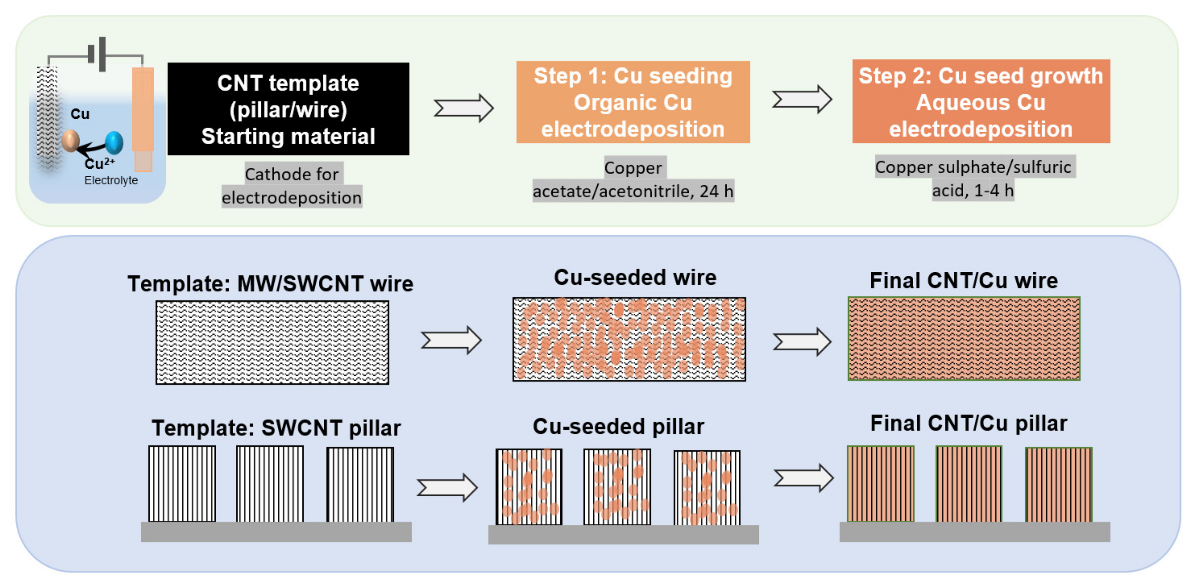
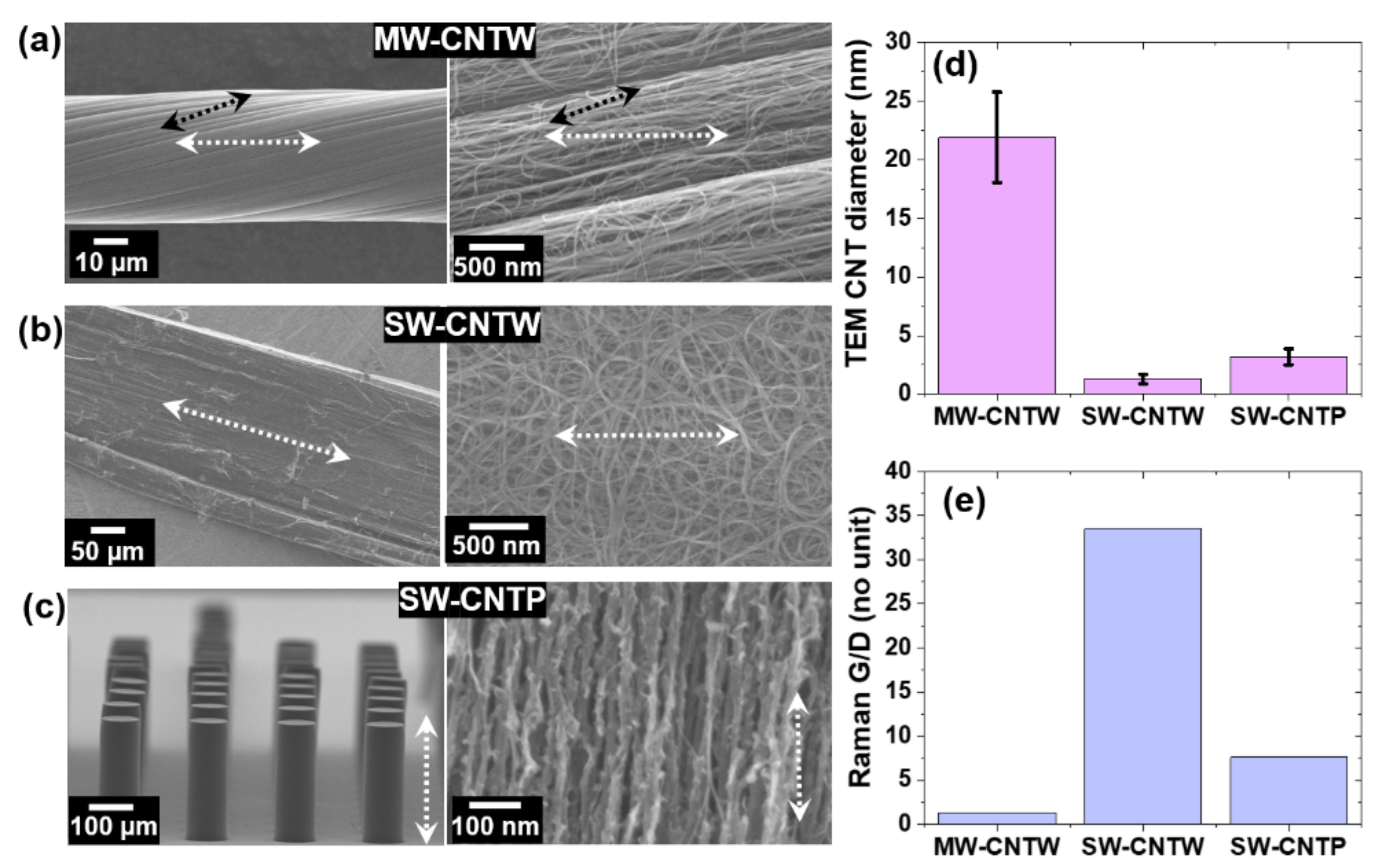
2.1. CNT Templates and Their Characterization

Three CNT templates with distinct nanotube characteristics were used in this study: (i) MW-CNTWs, (ii) SW-CNTWs, and (iii) SW-CNTPs. The MW-CNTWs were industrial wires (Muratec, Murata Machinery Ltd., Kyoto, Japan, 10 m spool) with density ≈ 0.5 g/cm3 and 40–50 μm in diameter). The wires were continuously twist-spun from vertical MW-CNT arrays (array height and CNT length ≈ 500 μm) grown on substrates by chemical vapor deposition (CVD). The SW-CNTWs (width ≈250 μm, density ≈ 0.06 g/cm3) were tapes directly obtained from a floating catalyst CVD reactor (CNT length 200–500 µm) [26,27]. Typical CNTW linear densities were ≈ 7–9 × 10⁻⁴ mg/mm. The SW-CNTPs were synthesized in-house by “supergrowth” (water-assisted CVD) on Si substrates, as described previously [7,28,29]. Arrays of pillars (diameter ≈ 100 µm, spaced ≈ 200 µm apart, pillar length and CNT length ≈ 300 µm, 95–98% porosity) were grown upon lithographically patterned CVD catalyst (≈3 nm thick Fe/40 nm thick Al2O3 buffer) deposited on patterned W lines (Figure S1, Supplementary Materials). The W lines served as electrical contacts between the pillars and W pads sputtered on Si substrates bearing the pillar array. This enabled contacting of all pillars in the array with the electrochemical workstation to permit Cu electrodeposition. To retain the pillar structure during electrodeposition, before composite fabrication, carbon was deposited from the gas phase amidst nanotubes and nanotube bundles in the SW-CNTPs (as reported in detail previously [7]).
Nanotube bundling and alignment, individual nanotube structure (diameter, wall number, etc.), and CNT graphitic structure in terms of Raman spectroscopy G-band to D-band intensity ratio (G/D) [30,31] were the chief template structural attributes we characterized. CNT bundling and alignment were observed by scanning electron microscopy (SEM, S4800, Hitachi High-Tech, Tokyo, Japan). Each individual nanotube structure was probed by transmission electron microscopy (TEM, Acceleration voltage = 200 kV, EM-002B, Topcon, Tokyo, Japan). TEM samples were prepared by dispersing templates (≈0.1 mg) in absolute ethanol (20 mL) by sonication and placing the dispersions on holey carbon TEM grids, which was followed by allowing the solvent to evaporate overnight. Diameters of 50 nanotubes (for each sample) obtained with ImageJ software were used to calculate average diameters. To obtain G/D ratios, Raman spectra were acquired from the templates (excitation laser wavelength = 532 nm, lateral resolution = 1 µm, Nicolet Almega XR Raman Spectrometer, Thermo-Electron, Tokyo, Japan).

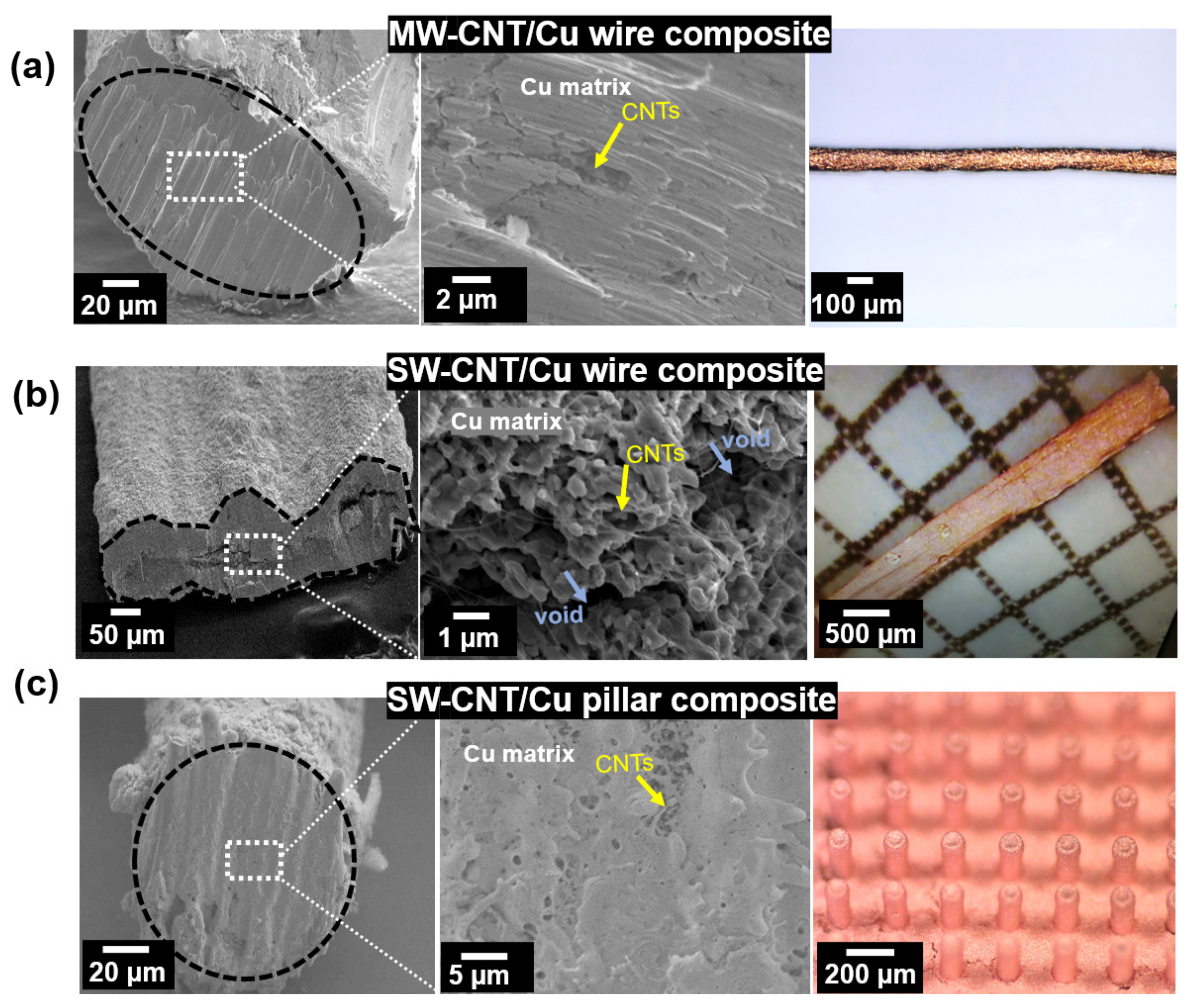
2.2. CNT/Cu Fabrication and Characterization

Composites were prepared from the three different CNT templates using two-step Cu electrodeposition (Figure 1). Routine aqueous electrolytes do not wet and infiltrate hydrophobic CNT templates and typically lead to only surface Cu deposition and core–sheath structured composites [8,11]. To enable internal Cu deposition and fabricate composites with CNTs and Cu uniformly mixed in the bulk [4,5,6,7,8,9,10,11], the two-step strategy was adopted. In the first step, Cu was seeded within templates from an organic electrolyte (anhydrous Cu(CH3COO)2 (Sigma Aldrich, Tokyo, Japan) in CH3CN (Wako pure chemicals, Osaka, Japan), 0.25 g/100 mL). To make the final composite samples, in the second step, the Cu seeds were grown by aqueous electrodeposition from commercial acidified aqueous CuSO4 electrolyte (40 g/L CuSO4.5H2O and ≈ 10 g/L H2SO4, without accelerators/suppressors, ATMI Inc., Danbury, Connecticut, USA). All electrodeposition experiments were carried out on VMP3 electrochemical workstation (Princeton applied research, Oakridge, TN, USA) at constant current mode. The electrodeposition set-up consisted of the CNT template cathode and Cu anode separated by Teflon spacers. In case of the CNTWs, samples (≈2 cm long) were mounted on a stainless-steel (SS) mesh sheet and mechanically clamped using SS clips. This arrangement was connected to the electrochemical station as the working electrode. In case of SW-CNTPs, the Si substrate bearing the pillars was directly used as the cathode (configuration illustrated in schematic shown in Figure S1, Supplementary Materials), which was connected to the electrochemical workstation through the sputtered W pad using crocodile clips.
The seeding condition i.e., current density (and time) for MW-CNTWs was 2.5 mA/cm2 (24 h), and that for SW-CNTWs and SW-CNTPs was 0.25 mA/cm2 (24 h). Subsequent aqueous deposition was carried out at 10 mA/cm2 (1 h) for MW-CNTWs and at 2.5 mA/cm2 (4 h) for SW-CNTWs and SW-CNTPs. CNT/Cu fabrication parameters were optimized and fixed based on our previous studies [9,10]. Excess electrolyte was removed by rinsing with CH3CN and deionized water after seeding and aqueous deposition, respectively. After each deposition step, samples were vacuum-dried (100 °C, 1 h) and subjected to reductive annealing (250 °C, 3 h, 150 cm3/min in H2 flow) to remove any Cu oxides.
We characterized the composite internal structures to ensure CNT-Cu mixing by cross-sectional SEM (CS-SEM, S4800, Hitachi High-Tech, Tokyo, Japan). In case of wires, cross-sections were obtained by slicing with high-precision scissors. For SW-CNT/Cu pillars, individual pillars were dislodged from the array and sliced using laser cutting (YO4 laser, Telecentric MD-T1000, Osaka, Japan). CNT/Cu densities were calculated from sample mass (resolution = 0.1 μg, UMX2, Mettler Toledo, Tokyo, Japan), length, and SEM or optical microscopy diameters (average 5 points).
Electrical resistances were acquired using a 4-probe set-up (PS-100 probe station, Lakeshore Cryotronics, Westerville, OH, USA and B1500A analyzer, Keysight, Tokyo, Japan). Contacting was done directly with samples using 25-micron-diameter Cu-Be probes on ≈ 1 cm long wire samples or on individual pillars dislodged from the substrate. Inter-probe distances to calculate conductivities was measured under an optical microscope. Cross-section areas were measured from CS-SEM images using ImageJ software. At least three values were measured for each wire sample, and averages were used for conductivity calculations. High-temperature resistances (up to 373 K) were obtained (at 10−3 Pa) with sample temperature regulated by a heating stage (controlled by Lakeshore Model 236 controller, Lakeshore Cryotronics, Westerville, OH, USA) to calculate TCR values. TCR was calculated as the slope of normalized resistance (measured resistance normalized by room temperature resistance, R/R298) vs. temperature difference (difference between measurement temperature and room temperature, T-T298) plot. Average and standard deviation values for electrical performance measurements from (at least) 3 samples of each type are presented. Electrical performances of neat Cu wires (100 μm diameter, 99.9% purity, Nilaco, Tokyo, Japan) and CNT templates were also measured for reference.

3. Results

CNT template SEM, TEM, and Raman spectroscopy characterization reveals key differences in the structure of nanotubes used for CNT/Cu fabrication (Figure 2). Electrical conductivities and their temperature stabilities (TCR) of composites consisting of different nanotube structures show distinct variations even with similar CNT-Cu mixing and composite internal structures (Figure 3 and Figure 4, and Table 1). Differences in the nanotube structural parameters of the three templates as well as the structure and performances of the respective composites are discussed in Section 3.1 and Section 3.2.

3.1. Nanotube Attributes in the CNT Templates

Nanotubes in MW-CNTWs (Figure 2a) are in general aligned along the twist direction, while in SW-CNTWs, nanotubes are entangled without any alignment (Figure 2b). Both types of wires can be expected to have multiple nanotube–nanotube junctions and ends due to the CNT length obtained at the synthesis stage (<500 µm), which is much shorter than macroscopic wire length scales (i.e., several meters). In SW-CNTPs (Figure 2c, nanotubes are in general aligned along the pillar axis and run end-to-end spanning the entire pillar length. All templates consist of spaces between nanotubes/nanotube bundles into which Cu2+ ions infiltrate and deposit copper during composite fabrication. As discussed in a previous work, appropriate template porosity and low densities are vital for optimal internal Cu electrodeposition, especially during the seeding step [10].
TEM analysis (Figure 2d and Figure S2a, Supplementary Materials) confirms the diameter and nanotube type constituting the templates. Nanotube diameters in MW-CNTWs, SW-CNTWs, and SW-CNTPs are 21.9 ± 3.9 nm, 1.3 ± 0.4 nm, and 3.2 ± 0.7 nm, respectively. Extensive SEM and TEM CNT template analysis revealed very little metal CVD catalyst residues. MW-CNTW templates show >96 wt % CNTs and catalyst residues < 1 wt % in air-TGA carried out from room temperature to 1000 °C, as reported in our earlier studies [8,10,11]. As mentioned in the experimental section, SW-CNTPs were obtained by water-assisted CVD, which is known to result in CNT materials of high purity with low catalyst residues [7,28,29]. Gas-phase carbon deposition was carried out on SW-CNTPs after CVD synthesis to include amorphous carbon in between nanotubes and nanotube bundles to retain pillar structural integrity during electrodeposition. Except for post-deposited amorphous carbon in the pillars, the purity of the three templates can be assumed to be comparable.
Raman spectra G peaks are observed at ≈1581/cm for MW-CNTWs and at 1588–1590/cm for SW-CNTWs and SW-CNTPs, which are typical for peak positions of MW- and SW-CNTs, respectively (Figure S2b, Supplementary Materials) [30,31]. In addition, RBM signatures distinctive to single-wall tubes [30,31] are observed from SW-CNTWs and SW-CNTPs, which are absent in the case of MW-CNTWs (Figure S3, Supplementary Materials). The Raman spectroscopy G/D ratios of the templates are also markedly different. The G/D—ratio of the graphitic G-band intensity (1580–1590/cm) and defective D-band (≈1340/cm) intensity—is a figure of merit of graphitic crystallinity of nanocarbon materials [30,31]. Imperfections in the graphitic lattice as well as amorphous impurities lead to lower G/D ratios. MW-CNTWs and SW-CNTPs show lower G/D (<7) than SW-CNTWs (G/D ≈ 33.5), indicating the better graphitic lattice quality of nanotubes in SW-CNTWs. To note, the gas-phase deposition of (amorphous) carbon in SW-CNTPs carried out after nanotube pillar CVD synthesis to retain the pillar structure during electrodeposition lowered G/D ratios from ≈7.6 to ≈1.1 (Figure S4, Supplementary Materials).
To summarize the differences in template nanotube characteristics: the twist-spun MW-CNTWs consist of low-G/D nanotubes with multiple ends and nanotube–nanotube junctions. SW-CNTWs are composed of high-G/D crystalline single-wall nanotubes (≈1.3 nm in diameter), also comprising of multiple ends and junctions. In SW-CNTPs, low-G/D (lower crystallinity) aligned single-wall tubes ≈ 3 nm in diameter run end-to-end with additional (amorphous) carbon. These nanotube characteristics can be assumed to be retained in the analogous CNT/Cu samples fabricated by two-step Cu electrodeposition.

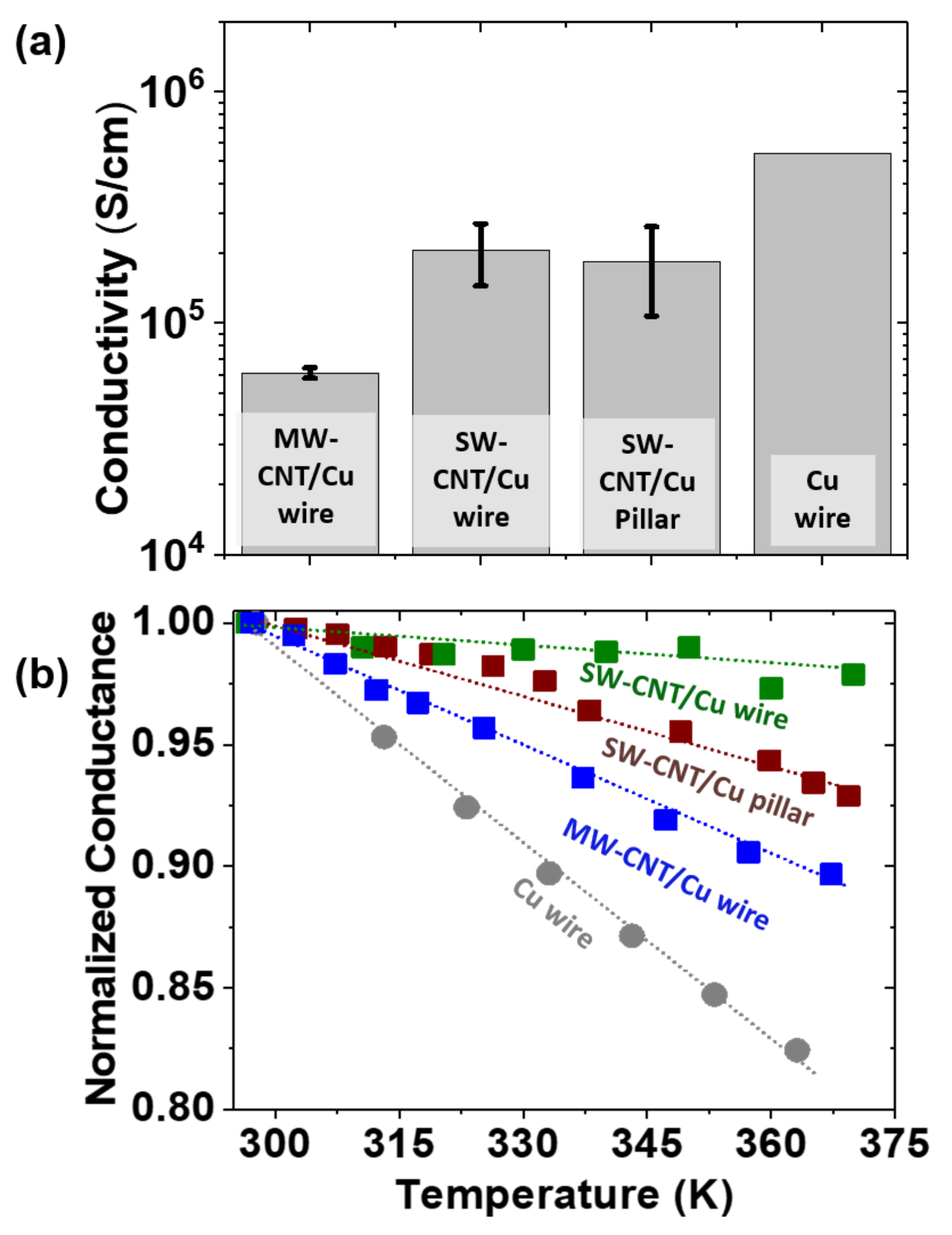
3.2. Composite Structure and Performances with Various Nanotube Attributes

CNT/Cu samples prepared from the three templates show nanotubes mixed uniformly in the Cu matrix with a regular Cu surface coating (SEM and optical microscopy images in Figure 3a–c and Figure S5, Supplementary Materials). CS-SEM after organic electrodeposition shows numerous Cu seeds (≈few hundreds of nm in diameter; see Figure S6, Supplementary Materials), which are vital for the subsequent seed growth and fabrication of final composites with uniform CNT–Cu mixing [9,10]. Around 20–40% of Cu mass in the final composites is estimated to be deposited during the Cu-seeding stage (organic deposition), with the rest deposited during aqueous deposition. In terms of composition, all three final composites show comparable Cu wt % of ≈98–99 wt % (Table S1) and are lighter than copper, as seen from the CNT/Cu densities (Table 1). In comparison to pure copper (density ≈ 8.9 g/cm3) [32], MW-CNT/Cu wire and SW-CNT/Cu pillar densities are ≈ 5.0 g/cm3, corresponding to ≈40–45 vol % nanotubes uniformly mixed in a copper matrix. SW-CNT/Cu wires show even lower densities (≈2 g/cm3), which can be attributed to voids observed in cross-sections (Figure 3b), in addition to the weight reduction arising from nanotubes uniformly mixed in the Cu matrix. These voids were inherent to these samples, which was possibly due to ultralow densities of the starting CNTW templates (<0.1 g/cm3). While the presence of voids in SW-CNT/Cu wires makes the nanotube vol % difficult to ascertain, based on sample masses and densities, CNT vol % in the composite wires is estimated to be ≈30–40 vol %.
The composite electrical performances in terms of conductivities and their temperature stabilities (TCR) are competitive to Cu, and variations in performances are observed among samples with different CNT attributes (Figure 4 and Table 1). The conductivities we measure for copper are comparable to standard values 5.85 × 10⁵ S/cm [32], confirming the validity of our electrical characterization protocol. The room temperature electrical conductivities (Figure 4a) of MW-CNT/Cu wires are ≈10% and an order of magnitude lower than that of Cu. SW-CNT/Cu wire and SW-CNT/Cu pillar conductivities are ≈ 3× higher than that of MW-CNT/Cu wires with similar Cu content (98–99 wt %, Table S1) and of the same order of magnitude as that of pure copper. The values range to ≈ 30–40% of Cu conductivity. In terms of specific conductivities (density-normalized values), for SW-CNT/Cu wires, SW-CNT/Cu pillars, and MW-CNT/Cu wires, the values are 1.4×, 0.5×, and 0.2× that of copper, respectively. The specific conductivity value of SW-CNT/Cu wires exceeding that of copper is in line with observations previously reported for SW-CNT/Cu composites [2,4,5]. Compared to parent CNT templates (Table S2, Supplementary Materials), CNT/Cu samples show two to three orders of magnitude higher conductivities, as may be expected from copper addition to nanotubes. The conductivities increase with Cu inclusion in each step of two-stage electrodeposition, as discussed in our previous studies [8,10]. For example, in MW-CNTWs, the conductivity increases from ≈261 S/cm for the neat wires to ≈350 S/cm for Cu-seeded wires and to ≈6.1 × 10⁴ S/cm for the final MW-CNT/Cu wires.
All composites show a decrease in conductance (normalized to room-temperature conductance) with temperature rise i.e., metal-like behavior (Figure 4b). However, composite conductances reduce less rapidly with temperature rise, and lower TCR values are observed vs. pure copper (Table 1, Figure S7). The lower the TCR, higher the temperature stability of the conductivity. The superior temperature stability of the conductivity of CNT/Cu is a widely reported merit of the composites arising from the participation of CNTs in the electron transport [4,6,8,12,13,15,16]. CNTs (and their ensembles) are known to show weak a temperature dependence of conductance (Table S2, Supplementary Materials [33,34,35]) and low TCR values. Rivalling composite conductivities, especially with high-temperature stability, are crucial for applications requiring conductors in electrical and electronic systems that operate above room temperature—ranging from motor windings, devices in aircrafts/cars, or even as interconnects in high-power electronics. As an aside, the macroscale wire and microscale pillar composites we have fabricated here are in forms that are relevant for real-world application as conducting wiring materials and vertical interconnect structures, respectively.
Comparing TCR values among the composites, SW-CNT/Cu wires show the lowest values (≈13% Cu-TCR), which is followed by the SW-CNT/Cu pillars (≈33% Cu-TCR) and MW-CNT/Cu wires (≈50% Cu-TCR). Compared to MW-CNT/Cu wires, the TCR of the SW-CNT/Cu composites are up to ≈ 4× lower. Considering both electrical conductivities and TCR, the superiority of the electrical performances of the samples in this study can be graded in decreasing order as SW-CNT/Cu wire > SW-CNT/Cu pillar > MW-CNT/Cu wire.
It is surprising that SW-CNT/Cu wires show copper-level electrical conductivities despite voids seen in the cross-section (Figure 3b). It could be construed that the copper outercoating rather than composite bulk containing both CNTs and Cu contributes dominantly to the conductivity. However, if this had been the case, the TCR values should have been closer to that of pure copper, as reported previously [8]. The combination of high conductivity and low TCR observed in SW-CNT/Cu wires despite voids indicate that the single-wall nanotubes in these composites play a significant role in composite electron transport.

4. Discussion

Our work lends experimental evidence to the impact of nanotube attributes on CNT/Cu composite electrical performances. Interpreting the results of our current study, we suggest that few-walled small-diameter nanotubes benefit composite electrical performances. In addition, high crystallinity (high G/D)/fewer nanotube ends and junctions/nanotube alignment may also contribute positively to composite performances.
Among the samples considered here, MW-CNT/Cu wires show lower electrical conductivites and temperature stabilities than SW-CNT/Cu composites (wires and pillars). The poorer performance of MW-CNT/Cu vs. SW-CNT/Cu could boil down to intrinsically lower conductivities of MW-CNTs and their aggregates [36] as well as geometric factors. For comparable nanotube vol %, small-diameter SW-CNTs afford a higher surface to volume ratio. Comparing SW-CNT/Cu pillars and MW-CNT/Cu wires (with ≈45 vol% nanotubes and G/D < 7), it is reasonable to assume the shared CNT-Cu interface area to be higher for SW-CNT/Cu than MW-CNT/Cu. In addition to the dissimilar shared interface areas stemming to large and small nanotube diameters, there are key differences between MW-CNT/Cu wires and SW-CNT/Cu pillars. While MW-CNT/Cu wires have multiple nanotube ends and junctions and CNTs are aligned along the wire twist direction (rather than along applied bias), in SW-CNT/Cu pillars, nanotubes run end-to-end aligned in general along applied bias. These factors may additionally contribute to the better performances of SW-CNT/Cu pillars vs. MW-CNT/Cu wires. Theoretical studies predict that CNTs aligned along the applied bias as well as fewer junctions and ends (that contribute to electron scattering) can lead to higher CNT/Cu electrical conductivities [24,25].
Among the SW-CNT/Cu samples, wires with high-G/D and smaller 1.3 nm diameter tubes show slightly better properties (especially, in terms of TCR) than pillars with low-G/D and 3 nm diameter tubes. This is the case despite SW-CNT/Cu wires containing voids, multiple tube ends and junctions, and a lack of CNT alignment vs. the SW-CNTs in pillars running end-to-end aligned along the applied bias. Based on the CNT vol% of the SW-CNT/Cu samples (pillars ≈ 45 vol%, wires estimated as ≈30–40 vol%), the higher shared interfacial areas arising from the smaller (≈1.3 nm) diameter tubes in the SW-CNT/Cu wires (vs. ≈3-nm tubes in pillars) may be a favorable factor. In addition to diameter, nanotube crystallinity variations seen as different G/D ratios (SW-CNTW G/D ≈ 33.5, SW-CNTPs G/D < 7) may also play a role. Higher CNT crystallinity is associated with higher intrinsic nanotube and CNT assembly conductivities [37], which may benefit composite performances. In addition, we hypothesize that better CNT lattice quality can also enhance CNT–Cu interactions and electron transport across the interface. In addition to the innate low G/D of nanotubes in the SW-CNTPs (G/D ≈ 7), amorphous carbon deposited after CVD synthesis (to retain pillar structure during electrodeposition; see Figure S4, Supplementary Materials) can perhaps act as additional scattering centers undermining electrical performances. A related effect on CNT/Cu thermal conductivity reduction with amorphous carbon inclusion was observed by Cho et al. [38], which was attributed to carbonaceous impurities at CNT–Cu interfaces acting as thermal barriers.
Our pointers from this study on favorable nanotube attributes i.e., small-diameter, few-wall, high-crystallinity nanotubes with fewer ends and junctions to achieve improved composite electrical properties, are unique in the literature. Studies dedicated to the influence of CNT characteristics on composite performances, especially electrical properties, are few. Most previous studies have attempted to corelate the composite mechanical performances (strength, hardness, etc.) with nanotube wall number, diameter, orientation, etc. [20,21,22,23]. Furthermore, a majority of these reports involve fabrication methodologies that damage CNTs/alter nanotube attributes during composite making, involving powder metallurgy techniques such as ball milling or CNT dispersion methods such as sonication [20,21,22,23]. In contrast, our composite fabrication methodology, i.e., the two-step electrodeposition of CNT templates, retains template nanotube attributes in the composites. Therefore, the differences in the composite electrical performances we observe in this study are attributable largely to the differences in the nanotube characteristics in the composites (and parent templates).
A drawback of our work is that multiple nanotube attributes (alignment, diameter, G/D, etc.) differ simultaneously in templates and consequently in the composite samples. The influence and impact of an individual CNT structural parameter—e.g., diameter—on composite performances, while all other attributes (G/D, wall number, length, alignment, presence/absence of nanotube junctions, etc.) are held constant, is unclear. In fact, fabricating composites with well-controlled CNT structures as well as synthesizing such regulated nanotubes (and templates) for composite fabrication is a major challenge for the CNT research community. In addition, despite the superior performances observed in SW-CNT/Cu in this work, our samples do not represent the true potential of SW-CNT-based composites because of the presence of amorphous carbon in the pillars and voids in the wires. Nevertheless, we believe that the results presented in this paper offer preliminary cues on the impact constituent nanotubes can exert on composite electrical properties for future research strategies toward performance tailoring.

5. Conclusions

In this work, we have attempted to demonstrate the impact of nanotube structural parameters on CNT/Cu electrical performances. We prepared three types of composites—MW-CNT/Cu wires, SW-CNT/Cu wires, and SW-CNT/Cu pillars—by two-step Cu electrodeposition of MW-CNTW, SW-CNTW, and SW-CNTP templates. The nanotube structural parameters in the respective templates (diameter, G/D, alignment, etc.) were characterized by SEM, TEM, and Raman spectroscopy. Our results indicate that few-walled small-diameter nanotubes are beneficial for composite electrical performances to achieve better temperature-stable conductivities. In addition, our data suggest that high CNT crystallinity (high G/D), fewer nanotube ends and junctions, and nanotube alignment along the bias direction may also positively influence the composite performances. SW-CNT/Cu wires and pillars outperformed MW-CNT/Cu wires with ≈3× higher room-temperature conductivities (values reaching 30–40% of Cu conductivity) even with comparable CNT vol % (≈45 vol %). SW-CNT/Cu also showed better temperature stability of conductivity, with up to 4× lower TCR than MW-CNT/Cu wires. Our results contribute unambiguous experimental evidence for the effect of CNT structural parameters on composite electrical performances enabled by a unique composite-making methodology (two-step Cu electrodeposition of CNT templates) that retains nanotube attributes during the fabrication. We believe that our results can be used as hints for electrical performance tailoring of CNT/Cu to develop these materials as lightweight temperature-stable electrical conductors with performances rivalling copper for real-world applications.

Supplementary Materials

The following are available online at https://www.mdpi.com/article/10.3390/c7040078/s1, Figure S1: (Left) Top-view of SW-CNTP array on W lines that act as electrical contacts for Cu electrodeposition. (Right) Schematic of the SW-CNTP array on Si substrate (top-view) used as cathode for Cu electrodeposition, Figure S2: Example (a) TEM images and (b) Raman spectra of MW-CNTW, SW-CNTW, and SW-CNTP samples used for CNT/Cu fabrication, Figure S3: Radial breathing mode region in the Raman spectra of nanotube templates used for CNT/Cu fabrication, Figure S4: Raman spectra and SEM images of SW-CNTP before and after carbon coating, Figure S5: SEM images of SW-CNT/Cu pillars (array and individual pillar), Figure S6: Cross-section SEM images of the Cu-seeded MW-CNTW, SW-CNTW, and SW-CNTP samples after organic Cu electrodeposition and H2 reduction, Figure S7: Measured resistance normalized by room-temperature resistance, R/R298 vs. difference between measurement temperature and room temperature, T-T298, Table S1: Cu content (wt %) in and cross-section areas of CNT/Cu composites, Table S2: Conductivity and TCR of CNT templates used for CNT/Cu fabrication.

Author Contributions

Conceptualization, methodology, validation and investigation, R.S. and A.S.; Conceptualization, D.F. and K.H.; Investigation, G.C.; Writing—original draft preparation, R.S.; Writing—review and editing, R.S., A.S., G.C., D.F., T.Y., K.K. and K.H.; Project administration, T.Y., D.F., A.S., K.K. and K.H.; Funding acquisition, R.S., A.S. and K.H. All authors have read and agreed to the published version of the manuscript.

Funding

This research was partially funded by the Japan Society for the Promotion of Science (JSPS) by JSPS KAKENHI Grant (Number JP 18F18050) through the JSPS international research fellowship.

Data Availability Statement

Raw data are available from authors on request.

Acknowledgments

We are grateful to M. Nishimura, H. Oosako, R. Shiina, S. Nemoto and M. Irie for their technical support. We thank Muratec, Murata Machinery Ltd. for providing the multi-wall CNT wires used in this work.

Conflicts of Interest

The authors declare no conflict of interest.

References

  1. Daneshvar, F.; Chen, H.; Noh, K.; Sue, H.J. Critical challenges and advances in the carbon nanotube–metal interface for next-generation electronics. Nanoscale Adv. 2021, 3, 942–962. [Google Scholar] [CrossRef]
  2. Sundaram, R.M.; Sekiguchi, A.; Sekiya, M.; Yamada, T.; Hata, K. Copper/carbon nanotube composites: Research trends and outlook. R. Soc. Open Sci. 2018, 5, 180814. [Google Scholar] [CrossRef] [Green Version]
  3. Tehrani, M. Advanced Electrical Conductors: An Overview and Prospects of Metal Nanocomposite and Nanocarbon Based Conductors. Phys. Status Solidi (A) 2021, 218, 2000704. [Google Scholar] [CrossRef]
  4. Subramaniam, C.; Yamada, T.; Kobashi, K.; Sekiguchi, A.; Futaba, D.N.; Yumura, M.; Hata, K. One hundred fold increase in current carrying capacity in a carbon nanotube–copper composite. Nat. Commun. 2013, 4, 2202. [Google Scholar] [CrossRef] [PubMed] [Green Version]
  5. Subramaniam, C.; Sekiguchi, A.; Yamada, T.; Futaba, D.N.; Hata, K. Nano-scale, planar and multi-tiered current pathways from a carbon nanotube–copper composite with high conductivity, ampacity and stability. Nanoscale 2016, 8, 3888–3894. [Google Scholar] [CrossRef] [PubMed]
  6. Sun, S.; Mu, W.; Edwards, M.; Mencarelli, D.; Pierantoni, L.; Fu, Y.; Jeppson, K.; Liu, J. Vertically aligned CNT-Cu nano-composite material for stacked through-silicon-via interconnects. Nanotechnology 2016, 27, 335705. [Google Scholar] [CrossRef]
  7. Chen, G.; Sundaram, R.; Sekiguchi, A.; Hata, K.; Futaba, D.N. Through-Silicon-Via Interposers with Cu-Level Electrical Conductivity and Si-Level Thermal Expansion Based on Carbon Nanotube-Cu Composites for Microelectronic Packaging Applications. ACS Appl. Nano Mater. 2020, 4, 869–876. [Google Scholar] [CrossRef]
  8. Sundaram, R.; Yamada, T.; Hata, K.; Sekiguchi, A. Electrical performance of lightweight CNT-Cu composite wires impacted by surface and internal Cu spatial distribution. Sci. Rep. 2017, 7, 1–11. [Google Scholar] [CrossRef]
  9. Sundaram, R.; Yamada, T.; Hata, K.; Sekiguchi, A. The influence of Cu electrodeposition parameters on fabricating structurally uniform CNT-Cu composite wires. Mater. Today Commun. 2017, 13, 119–125. [Google Scholar] [CrossRef]
  10. Sundaram, R.; Yamada, T.; Hata, K.; Sekiguchi, A. The importance of carbon nanotube wire density, structural uniformity, and purity for fabricating homogeneous carbon nanotube–copper wire composites by copper electrodeposition. Jpn. J. Appl. Phys. 2018, 57, 04FP08. [Google Scholar] [CrossRef] [Green Version]
  11. Sundaram, R.; Yamada, T.; Hata, K.; Sekiguchi, A. Thermal expansion of Cu/carbon nanotube composite wires and the effect of Cu-spatial distribution. J. Mater. Res. Technol. 2020, 9, 6944–6949. [Google Scholar] [CrossRef]
  12. Leggiero, A.P.; Driess, S.D.; Loughran, E.D.; McIntyre, D.J.; Hailstone, R.K.; Cress, C.D.; Puchades, I.; Landi, B.J. Platinum nanometal interconnection of copper–carbon nanotube hybrid electrical conductors. Carbon 2020, 168, 290–301. [Google Scholar] [CrossRef]
  13. McIntyre, D.J.; Leggiero, A.P.; Hailstone, R.K.; Puchades, I.; Cress, C.D.; Landi, B.J. Integrated Titanium-Carbon Nanotube Conductors via Joule-Heating Driven Chemical Vapor Deposition. ECS Trans. 2020, 97, 321–327. [Google Scholar] [CrossRef]
  14. McIntyre, D.J.; Hirschman, R.K.; Puchades, I.; Landi, B.J. Enhanced copper–carbon nanotube hybrid conductors with titanium adhesion layer. J. Mater. Sci. 2020, 55, 6610–6622. [Google Scholar] [CrossRef]
  15. Leggiero, A.P.; Trettner, K.J.; Ursino, H.L.; McIntyre, D.J.; Schauer, M.; Zeira, E.; Cress, C.D.; Landi, B.J. High conductivity copper–carbon nanotube hybrids via site-specific chemical vapor deposition. ACS Appl. Nano Mater. 2018, 2, 118–126. [Google Scholar] [CrossRef]
  16. Shuai, J.; Xiong, L.; Zhu, L.; Li, W. Enhanced strength and excellent transport properties of a superaligned carbon nanotubes reinforced copper matrix laminar composite. Compos. Part. A Appl. Sci. Manuf. 2016, 88, 148–155. [Google Scholar] [CrossRef]
  17. Shuai, J.; Xiong, L.Q.; Lin, Z.H.U.; Li, W.Z. Effects of ply-orientation on microstructure and properties of super-aligned carbon nanotube reinforced copper laminar composites. Trans. Nonferrous Met. Soc. China 2017, 27, 1747–1758. [Google Scholar] [CrossRef]
  18. Mendoza, M.E.; Solórzano, I.G.; Brocchi, E.A. Mechanical and electrical characterization of Cu-2 wt.% SWCNT nanocomposites synthesized by in situ reduction. Mater. Sci. Eng. A 2012, 544, 21–26. [Google Scholar] [CrossRef]
  19. Milowska, K.Z.; Ghorbani-Asl, M.; Burda, M.; Wolanicka, L.; Ćatić, N.; Bristowe, P.D.; Koziol, K.K. Breaking the electrical barrier between copper and carbon nanotubes. Nanoscale 2017, 9, 8458–8469. [Google Scholar] [CrossRef]
  20. Nayan, N.; Shukla, A.K.; Chandran, P.; Bakshi, S.R.; Murty, S.V.S.N.; Pant, B.; Venkitakrishnan, P.V. Processing and characterization of spark plasma sintered copper/carbon nanotube composites. Mater. Sci. Eng. A 2017, 682, 229–237. [Google Scholar] [CrossRef]
  21. Guiderdoni, C.; Pavlenko, E.; Turq, V.; Weibel, A.; Puech, P.; Estournès, C.; Peigney, A.; Bacsa, W.; Laurent, C. The preparation of carbon nanotube (CNT)/copper composites and the effect of the number of CNT walls on their hardness, friction and wear properties. Carbon 2013, 58, 185–197. [Google Scholar] [CrossRef] [Green Version]
  22. Sun, Y.; Chen, Q. Diameter dependent strength of carbon nanotube reinforced composite. Appl. Phys. Lett. 2009, 95, 021901. [Google Scholar] [CrossRef] [Green Version]
  23. Zhao, S.; Zheng, Z.; Huang, Z.; Dong, S.; Luo, P.; Zhang, Z.; Wang, Y. Cu matrix composites reinforced with aligned carbon nanotubes: Mechanical, electrical and thermal properties. Mater. Sci. Eng. A 2016, 675, 82–91. [Google Scholar] [CrossRef]
  24. Ghorbani-Asl, M.; Bristowe, P.D.; Koziol, K. A computational study of the quantum transport properties of a Cu–CNT composite. Phys. Chem. Chem. Phys. 2015, 17, 18273–18277. [Google Scholar] [CrossRef] [Green Version]
  25. Hjortstam, O.; Isberg, P.; Söderholm, S.; Dai, H. Can we achieve ultra-low resistivity in carbon nanotube-based metal composites? Appl. Phys. A 2004, 78, 1175–1179. [Google Scholar] [CrossRef]
  26. Kobayashi, K.; Shukla, B.; Ohmori, S.; Kiyomiya, M.; Hirai, T.; Kuwahara, Y.; Saito, T. Wall-Number Selectivity in Single/Double-Wall Carbon Nanotube Production by Enhanced Direct Injection Pyrolytic Synthesis. Jpn. J. Appl. Phys. 2013, 52(10R), 105102. [Google Scholar] [CrossRef]
  27. Saito, T.; Ohshima, S.; Okazaki, T.; Ohmori, S.; Yumura, M.; Iijima, S. Selective diameter control of single-walled carbon nanotubes in the gas-phase synthesis. J. Nanosci. Nanotechnol. 2008, 8, 6153–6157. [Google Scholar] [CrossRef] [PubMed]
  28. Chen, G.; Dodson, B.; Hedges, D.M.; Steffensen, S.C.; Harb, J.N.; Puleo, C.; Galligan, C.; Ashe, J.; Vanfleet, R.R.; Davis, R.C. Fabrication of high aspect ratio millimeter-tall free-standing carbon nanotube-based microelectrode arrays. ACS Biomater. Sci. Eng. 2018, 4, 1900–1907. [Google Scholar] [CrossRef] [PubMed]
  29. Hata, K.; Futaba, D.N.; Mizuno, K.; Namai, T.; Yumura, M.; Iijima, S. Water-assisted highly efficient synthesis of impurity-free single-walled carbon nanotubes. Science 2004, 306, 1362–1364. [Google Scholar] [CrossRef] [Green Version]
  30. Saito, R.; Hofmann, M.; Dresselhaus, G.; Jorio, A.; Dresselhaus, M.S. Raman spectroscopy of graphene and carbon nanotubes. Adv. Phys. 2011, 60, 413–550. [Google Scholar] [CrossRef]
  31. Reich, S.; Thomsen, C.; Maultzsch, J. Carbon Nanotubes: Basic Concepts and Physical Properties, 1st ed.; John Wiley & Sons: Weinheim, Germany, 2004; pp. 142–174. [Google Scholar]
  32. Haynes, W.M. (Ed.) Thermal and physical properties of pure metals. In CRC Handbook of Chemistry and Physics, 97th ed.; CRC Press, Taylor and Francis: Boca Raton, FL, USA, 2016; pp. 12–217. [Google Scholar]
  33. Behabtu, N.; Young, C.C.; Tsentalovich, D.E.; Kleinerman, O.; Wang, X.; Ma, A.W.; Bengio, E.A.; Waarbeek, R.F.; de Jong, J.J.; Hoogerwerf, R.E.; et al. Strong, light, multifunctional fibers of carbon nanotubes with ultrahigh conductivity. Science 2013, 339, 182–186. [Google Scholar] [CrossRef] [PubMed] [Green Version]
  34. Zhao, Y.; Wei, J.; Vajtai, R.; Ajayan, P.M.; Barrera, E.V. Iodine doped carbon nanotube cables exceeding specific electrical conductivity of metals. Sci. Rep. 2011, 1, 1–5. [Google Scholar] [CrossRef] [PubMed] [Green Version]
  35. Niven, J.F.; Johnson, M.B.; Juckes, S.M.; White, M.A.; Alvarez, N.T.; Shanov, V. Influence of annealing on thermal and electrical properties of carbon nanotube yarns. Carbon 2016, 99, 485–490. [Google Scholar] [CrossRef] [Green Version]
  36. Bulmer, J.S.; Kaniyoor, A.; Elliott, J.A. A Meta-Analysis of Conductive and Strong Carbon Nanotube Materials. Adv. Mater. 2021, 33, 2008432. [Google Scholar] [CrossRef] [PubMed]
  37. Tsentalovich, D.E.; Headrick, R.J.; Mirri, F.; Hao, J.; Behabtu, N.; Young, C.C.; Pasquali, M. Influence of carbon nanotube characteristics on macroscopic fiber properties. ACS Appl. Mater. Interfaces 2017, 9, 36189–36198. [Google Scholar] [CrossRef] [PubMed]
  38. Cho, S.; Kikuchi, K.; Kawasaki, A. On the role of amorphous intergranular and interfacial layers in the thermal conductivity of a multi-walled carbon nanotube–copper matrix composite. Acta Mater. 2012, 60, 726–736. [Google Scholar] [CrossRef]
Figure 1. Schematic representing CNT/Cu fabrication by two-step Cu electrodeposition of CNT templates—wires and pillars.
Carbon 07 00078 g001
Figure 2. Characterization of CNT templates used for CNT/Cu fabrication. Low- and high-magnification SEM images of (a) MW-CNTW, (b) SW-CNTW, and (c) SW-CNTP samples. White arrows indicate wire/pillar axis. Black arrows in (a) indicate twist direction. (d) TEM CNT diameter and (e) Raman G/D ratios of MW-CNTW, SW-CNTW, and SW-CNTP samples.
Carbon 07 00078 g002
Figure 3. Low- and high-magnification CS-SEM images and optical micrographs of (a) MW-CNT/Cu wires, (b) SW-CNT/Cu wires, and (c) SW-CNT/Cu pillars.
Carbon 07 00078 g003
Figure 4. Electrical performances of CNT/Cu composites: (a) room-temperature electrical conductivities and (b) normalized conductance (to room-temperature conductance) vs. temperature plot.
Carbon 07 00078 g004
Table 1. Composite properties (density, room temperature electrical conductivity, and TCR) and parent template nanotube characteristics (CNT diameter and G/D).
SampleComposite PropertiesCNT Attributes
Density
(g/cm3)
Conductivity (S/cm)TCR
(/K)
Diameter (nm)G/DRemarks
MW-CNT/Cu wire5.1 ± 0.36.1 × 104
± 3.2 × 10³
1.8 × 10⁻³
± 2.0 × 10⁻⁴
21.9 ± 3.9 ≈500 µm long MWCNTs with multiple ends and nanotube–nanotube junctions
1.3
SW-CNT/Cu wire2.2 ± 0.22.1 × 105
± 6.2 × 10⁴
4.4 × 10⁻⁴
± 1.9 × 10⁻⁴
1.3 ± 0.433.5≈200–500 µm long SWCNTs with multiple ends and nanotube–nanotube junctions
SW-CNT/Cu pillar5.0 ± 0.2
1.8 × 10⁵
± 7.6 × 10⁴
1.1 × 10⁻³
± 2.1 × 10⁻⁴
3.2 ± 0.77.6≈300 µm long SWCNTs (aligned) running end-to-end
Cu wire8.95.4 × 105
± 2.8 × 10³
3.3 × 10⁻³
± 4.3 × 10⁻⁴
---
Publisher’s Note: MDPI stays neutral with regard to jurisdictional claims in published maps and institutional affiliations.

