Article

Synthesis of Carbon Nanotubes by Plasma-Enhanced Chemical Vapor Deposition Using Fe1−xMnxO Nanoparticles as Catalysts: How Does the Catalytic Activity of Graphitization Affect the Yields and Morphology?

Division of Applied Chemistry, Faculty of Engineering, Hokkaido University, Kita 13 Nishi 8 Kita-ku, Sapporo 060-8628, Japan
*
Author to whom correspondence should be addressed.
Submission received: 26 June 2019 / Revised: 1 August 2019 / Accepted: 6 August 2019 / Published: 8 August 2019
(This article belongs to the Special Issue Plasma Processing for Carbon-based Materials)

Abstract

:
The choice of a catalyst for carbon nanotube (CNT) growth is critical to controlling the morphology and chirality of the final product. Plasma-enhanced chemical vapor deposition (PECVD) can alleviate the requirements of the catalyst, i.e., they must be active for both the decomposition of the source gas and graphitization in the conventional thermal CVD. However, it is still not well understood how the catalytic activity of the graphitization affects the yield and quality of CNTs. In this paper, we systematically investigated the influence of the catalytic activity of graphitization by tuning the composition of Fe1−xMnxO (x = 0–1) nanoparticles as catalysts. As the Mn component increased, the number of CNTs decreased because Mn has no catalytic function of the graphitization. The quality of CNTs also affected by the inclusion of the Mn component. Our study may provide useful information to develop a new catalyst for CNT growth in PECVD.

Graphical Abstract

1. Introduction

The carbon nanotube (CNT) has been widely studied since its discovery [1,2] due to its excellent properties such as high thermal conductivity [3], toughness [4] and high carrier mobility [5,6,7,8,9]. Several kinds of synthetic methods have been established to grow the CNTs, for instance, arc discharge [10,11], laser ablation [12] and thermal chemical vapor deposition (CVD) [13,14,15,16,17,18,19,20,21]. The thermal CVD is currently the most widely used technique for the CNT production due to its high yield, high quality and ease of use. Two primary methods of HiPCO [22] and super-growth [23] were invented by Nikolaev et al. and Hata et al., respectively, for the mass production of the single-walled CNT (SWCNT). After the invention of these two methods, many researchers tried to synthesize SWCNTs with single chirality for over ten years because the chirality determines the electronic property of the SWCNT. (6, 5) SWCNTs with chirality in a proportion higher than 50% were produced using the CoMo catalyst supported by porous silica [14,24]. When using the FeRu catalyst, the chirality depends on the reaction temperature; (6, 5) SWCNTs and a mixture of (8, 4) and (7, 5) SWCNTs are synthesized at 600 °C and 850 °C, respectively [15]. In 2014, (6, 6) SWCNTs were grown using singly capped ultrashort SWCNTs that were synthesized via barrel-shaped organic molecules (C96H54) [25]. A single chirality (12, 6) in a proportion more significant than 92% was achieved for the SWCNT growth using the W-Co nanocrystal catalyst [26]. For further improvement of the quality of CNT, many researchers are still intensively exploring the catalysts for the SWCNT growth because the SWCNT growth with a higher selectivity is desirable for electronic applications.
However, searching for a new catalyst is very challenging due to the strict requirements for the catalyst for the thermal CVD, which must possess both functions of decomposition of the source gas and graphitization of the carbon species [27,28,29,30]. The plasma-enhanced CVD (PECVD) can alleviate such strict requirements for the CNT growth because a high energy plasma makes active carbon species. Another advantage of the PECVD is that the amount of supplied ionized carbon species onto the surface of the catalyst can be tuned by applying a voltage to the substrate. Kato et al. demonstrated that the chirality distribution and growth rate of the SWCNTs in the PECVD could be controlled by tuning the size of the nanoparticles (catalysts) and the flow rate of H2 [31,32]. Although many articles reported the low-temperature synthesis of CNTs, synthesis of free-standing CNTs and synthesis of horizontally aligned CNTs by PECVD [33,34,35,36], it is still not well studied how the catalytic activity of the graphitization influences the yield and morphology of CNTs.
The purpose of this study is to systematically investigate how catalytic activity affects the yield and morphology of CNTs, which must be well understood before searching for a new catalyst for the CNT growth. In order to achieve this purpose, Fe1−xMnxO (x = 0–1) was selected as a catalytic nanoparticle because it is well-known that Fe is a suitable catalyst in the thermal CVD while Mn is not. Furthermore, it is easy to tune the chemical composition, which is x by controlling the synthetic conditions. Our study may provide useful information to develop a new catalyst for CNT growth.

2. Materials and Methods

The Fe1−xMnxO nanoparticles that were synthesized according to Hou [37] were used for the catalyst of the CNT growth. It was confirmed that the same procedure to make FeO nanoparticles can be used for the synthesis of the Fe1−xMnxO nanoparticles if the corresponding ratio of the acetylacetone complexes (starting materials) is used except when x = 1 (pristine MnO). We found that the MnO particles synthesized following the same procedure as Hou reported [37] were large (~200 nm). Therefore, the hot injection method [38,39] was used for preparing the MnO nanoparticles. The ratio of the acetylacetone complexes in the source materials is summarized in Table 1.
We found that FeO nanoparticles were reduced into Fe nanoparticles during PECVD by the active species generated in the plasma, which was confirmed by acquiring an electron diffraction pattern of the nanoparticles after the PECVD as shown in Figure 1. The inset shows a transmission electron microscope (TEM, JEM-2010, JEOL, Tokyo, Japan) image of the Fe nanoparticles attached to the CNTs. We further confirmed with a scanning electron microscope (SEM, JSM-6500F, JEOL, Tokyo, Japan) that there was no significant difference in the CNT growth in both cases when we used FeO nanoparticles with and without hydrogen treatment as shown in Figure 2a,b. Therefore, we did not carry out any special treatment, such as hydrogen treatment to reduce FeO into Fe in this study.
The specially designed PECVD chamber that can directly monitor the temperature under a high bias voltage using a thermocouple was utilized in this study. The detailed geometry of the PECVD chamber was described in the previous report [40]. A SiO2(285 nm)/Si wafer was cut into several 1 × 1 cm2 pieces and cleaned by the RCA method [41], then an Al2O3 layer was deposited by sputtering, if necessary. The oxide nanoparticles dispersed in a hexane solution were dip-coated on the substrate in a glove box. The substrates were transferred to the chamber as quickly as possible because the monoxide nanoparticles are gradually oxidized in air. After the substrates were introduced into the PECVD chamber, then the chamber was evacuated. When the pressure reached 1 × 10⁻⁴ Pa, the substrate was heated to 650 °C, then methane (CH4) was introduced into the chamber. The pressure was adjusted to 70 Pa that is the optimal pressure to form a stable plasma. The radiofrequency plasma was turned on, and the power was fixed at 20 W. A bias voltage (−200 V) was applied to the substrate, and the shutter was opened to start the PECVD. After a 10 min reaction, the shutter was closed to stop the growth of the CNTs. The plasma and the heater were turned off to avoid any undesired reaction while cooling.
XRD (Rint Ultima 2000, Rigaku, Tokyo, Japan) was measured to identify the nanoparticles with Cu Kα radiation (λ = 0.154056 nm). A TEM (JEM-2010, JEOL, Tokyo, Japan) and an SEM (JSM-6500F, JEOL, Tokyo, Japan) were used to observe the morphology of the nanoparticles and CNTs. An energy dispersive X-ray spectrometer (EDS) attached to the TEM was used to conduct the elemental analysis. The structural order of the CNTs was analyzed by Raman spectroscopy (Renishaw Invia) with a 532 nm excitation laser.

3. Results and Discussion

The dispersity of the nanoparticles on a substrate is very important to make dense CNTs [42,43]. Hence we examined the dispersity on the six kinds of substrate: SiO2/Si(100), SiO2/Si(100) with scratches, Si(100), 7° off Si(100), a molybdenum plate and Al2O3/SiO2/Si. Only the Al2O3/SiO2/Si substrate was effective to uniformly disperse the FeO nanoparticles as shown in Figure 3a. The FeO nanoparticles on a SiO2/Si substrate aggregated, forming large clusters as seen in Figure 3b. Such aggregation also occurred when using the other four substrates (not shown). The dispersity of Fe nanoparticles on the Al2O3/SiO2/Si substrate was maintained even though the substrate was heated to 650 °C. To demonstrate how the Al2O3 layer influences a final product, the PECVD was carried out for the substrates with and without the Al2O3 layer. The density of CNT synthesized with the Al2O3 layer (Figure 4a) was much higher than that without the Al2O3 (Figure 4b) because the aggregation lowered the activity of the nanoparticles. This result clearly illustrates that the Al2O3 layer is useful for suppressing the aggregation of the FeO nanoparticles and for the dense CNT growth. The suppression of the aggregation can be explained by the rough surface of the Al2O3 layer, which prevents the particles from moving on the surface. It is noteworthy that the Al2O3 does not show the catalytic function for the CNT growth because nothing formed when the Al2O3/SiO2/Si substrates without FeO nanoparticles were used. This result also indicates that only the function of graphitization is required in PECVD because no CNT grew at 650 °C and the CNT growth was observed at above 800 °C when the conventional thermal CVD was carried out.
Figure 5 shows TEM images of four kinds of nanoparticles prepared as mentioned in the Experimental section. Since we focus on the catalytic function of the graphitization of nanoparticles, minor differences in the size and shape of nanoparticles can be ignored. The exclusion of the size and shape effects was justified by [44,45,46,47] those reported that multi-walled carbon nanotube (MWCNT) could be synthesized using nanoparticles with any shape when the size is smaller than ~100 nm. Therefore, the catalytic activities of Fe1−xMnxO particles were examined merely by tuning the composition ratio of the nanoparticles. The Mn ratios (x) were evaluated by TEM-EDS as x = 0.5 and 0.97 for (ii) and (iii), respectively (see Table 1). XRD patterns of four nanoparticles were obtained to identify the nanoparticles and to evaluate the compositional uniformity of the alloy as shown in Figure 6a. All nanoparticles were identified as fcc-structure monoxides from (111), (200), (220), (311), and (222) peaks. The shoulder peak at 34.5° for the pristine FeO is due to the surface oxidation of the FeO nanoparticles while acquiring the XRD pattern. Similar air oxidation was also observed in the previous study [37]. No peak splitting indicates that Fe and Mn were uniformly distributed in the Fe1−xMnxO nanoparticles. The (200) peaks were extracted to see the peak shift in Figure 6b clearly. The minimum variation of the peak shift is larger than the angular resolution, and the chemical composition can be calculated based on Vegard’s law that is formulated as follows
a F e 1 x M n x O = ( 1 x ) a F e O + x a M n O ,
where a F e 1 x M n x O is the lattice constant of Fe1−xMnxO, a F e O is one of the pristine FeO (0.2139 nm) and a M n O is one of the pristine MnO (0.2223 nm). The Mn ratios (x) of (ii) and (iii) were calculated as 0.5 and 0.9, respectively. These results are consistent with the chemical compositions evaluated by TEM-EDS analysis. It is concluded that the chemical composition of Fe1−xMnxO nanoparticles can be controlled by adjusting the ratio of the acetylacetone complexes in the source materials. The x estimated by both TEM-EDS and XRD are summarized in Table 1.
Figure 7 shows the surface morphologies of the substrates after the PECVD was carried out for all nanoparticles. The density of CNT decreased as Fe ratio decreased, then finally, nothing formed when the pristine MnO nanoparticles were used. The number density of CNT was roughly estimated from SEM images as 48 µm−2 for (i), 24 µm−2 for (ii) and 4 µm−2 for (iii). This result shows that the number of catalytic sites of graphitization decreased as the Mn ratio increased, which means that the catalytic activity of graphitization can be tuned by adjusting the composition ratio. It should be noted that the possibility of the existence of pure FeO nanoparticles in samples (ii) and (iii) is not likely considering the XRD result (Figure 6) that shows no phase separation. Samples (i) and (ii) were scrutinized by TEM and Raman spectroscopy to clarify the quality of the CNTs.
Figure 8a,b show the TEM image and the electron diffraction pattern of the CNTs for samples (i) and (ii). The tubular structure was seen for both samples, and most of the nanotubes were MWCNTs. The average number of graphene layers on the wall was calculated as 12 by assuming the interlayer distance of graphite (0.336 nm). The electron diffraction analysis shows the ring pattern attributed to the graphitic layered structure of (002) plane, which is from the side walls parallel to the direction of the electron beam [2,48]. The average diameters of the samples (i) and (ii) were estimated from Figure 8 as 18 ± 13 nm and 29 ± 14 nm, respectively. We concluded from this result that the diameter of the CNT was determined by the size of nanoparticles, not the chemical composition.
Raman spectra of the samples (i) and (ii) were also obtained to elucidate the quality of CNTs as shown in Figure 9. The quality of CNTs can be evaluated by calculating the intensity ratio of D peak (ID) and G peak (IG) because the G band is assigned to the intrinsic vibrational mode of CNT, on the other hand, the D band is assigned to the defect mode [49,50]. ID/IG was calculated as 0.7 for sample (i) which is comparable to the reported value (0.2–0.7) of CNT with high quality [49,50] while ID/IG was calculated as 1.7 for sample (ii) which is much larger than that of the sample (i). A large ID/IG of the sample (ii) indicates the inclusion of the amorphous component. Fe in Fe0.5Mn0.5O nanoparticles might not be mobile enough to make a nanotube with excellent crystallinity because the MnO is not reduced in the plasma environment and does not melt at this temperature (the melting point of the MnO is 1650 °C). Lowering the catalytic activity of graphitization due to the inclusion of the MnO caused the formation of the amorphous component. Combining this result and the fact that the number density of CNT decreased as Mn component increased, we concluded that only high catalytic activity of graphitization was required to grow CNT in PECVD because high energy plasma decomposed the source gas. Raman of radius breathing modes (RBM) was also observed for the sample (i) at the region between 150–250 cm−1 as shown in the inset of Figure 9 while no RBM was seen for sample (ii). The RBM proved that the existence of the SWCNTs with a diameter of 1–2 nm. The formation of the SWCNTs is probably because FeO nanoparticles were the smallest among four kinds of nanoparticles; hence, there was a chance to grow SWCNTs. On the other hand, SWCNT was not produced when using Fe0.5Mn0.5O nanoparticles due to the large size.

4. Conclusions

We studied how the catalytic activity of graphitization influences the growth of CNT using Fe1−xMnxO nanoparticles as catalysts in PECVD. The number density of CNT decreases as the ratio of Mn increases, which shows that the catalytic activity can be tuned by controlling the composition ratio. Our results show that only the catalytic function of graphitization affects the yield and quality of CNTs. Although Fe or Ni is recognized as one of the best catalysts in PECVD, the decomposition function Fe or Ni possesses is not actually needed. We believe that our study will encourage researchers to search for a new catalyst with the high catalytic activity of graphitization, which is not necessary to show the catalytic activity of decomposition of a source gas.

Author Contributions

T.Y., T.M., T.S. (Tatsuya Shiratori) and M.W. conducted research and performing the experiments to obtain data/evidence. T.Y. and T.N. essentially contributed in discussion and in preparing the manuscript. T.S. (Toshihiro Shimada) planned the research, acquired the financial support for the project and reviewed the manuscript.

Funding

This work is partly supported by KAKENHI 17H03380, MEXT JAPAN.

Acknowledgments

Instrumental analysis was supported by the Nanotechnology Platform at Hokkaido University by METI, Japan.

Conflicts of Interest

The authors declare no conflict of interest.

References

  1. Iijima, S.; Ichihashi, T. Single-shell carbon nanotubes of 1-nm diameter. Nature 1993, 363, 603–605. [Google Scholar] [CrossRef]
  2. Iijima, S. Helical microtubules of graphitic carbon. Nature 1991, 354, 56–58. [Google Scholar] [CrossRef]
  3. Hone, J.; Llaguno, M.; Biercuk, M.; Johnson, A.; Batlogg, B.; Benes, Z.; Fischer, J. Thermal properties of carbon nanotubes and nanotube-based materials. Appl. Phys. A 2002, 74, 339–343. [Google Scholar] [CrossRef]
  4. Wong, E.; Sheehan, P.; Lieber, C. Nanobeam Mechanics: Elasticity, Strength, and Toughness of Nanorods and Nanotubes. Science 1997, 277, 1971–1975. [Google Scholar] [CrossRef]
  5. Franklin, A. Electronics: The road to carbon nanotube transistors. Nature 2013, 498, 443–444. [Google Scholar] [CrossRef] [PubMed]
  6. Tans, S.; Verschueren, A.; Dekker, C. Room-temperature transistor based on a single carbon nanotube. Nature 1998, 393, 49–52. [Google Scholar] [CrossRef]
  7. Martel, R.; Schmidt, T.; Shea, H.; Hertel, T.; Avouris, P. Single-and multi-wall carbon nanotube field-effect transistors. Appl. Phys. Lett. 1998, 73, 2447–2449. [Google Scholar] [CrossRef]
  8. Zhong, G.; Iwasaki, T.; Honda, K.; Furukawa, Y.; Ohdomari, I.; Kawarada, H. Low Temperature Synthesis of Extremely Dense and Vertically Aligned Single-Walled Carbon Nanotubes. Jpn. J. Appl. Phys. 2005, 44, 1558–1561. [Google Scholar] [CrossRef]
  9. Nakai, Y.; Honda, K.; Yanagi, K.; Kataura, H.; Kato, T.; Yamamoto, T.; Maniwa, Y. Giant Seebeck coefficient in semiconducting single-wall carbon nanotube film. Appl. Phys. Express 2014, 7, 025103. [Google Scholar] [CrossRef] [Green Version]
  10. Ebbesen, T.; Ajayan, P. Large-scale synthesis of carbon nanotubes. Nature 1992, 358, 220–222. [Google Scholar] [CrossRef]
  11. Ando, Y.; Iijima, S. Preparation of Carbon Nanotubes by Arc-Discharge Evaporation. Jpn. J. Appl. Phys. 1993, 32, L107–L109. [Google Scholar] [CrossRef]
  12. Thess, A.; Lee, R.; Nikolaev, P.; Dai, H.; Petit, P.; Robert, J.; Xu, C.; Lee, Y.; Kim, S.; Rinzler, A.; et al. Crystalline Ropes of Metallic Carbon Nanotubes. Science 1996, 273, 483–487. [Google Scholar] [CrossRef] [PubMed] [Green Version]
  13. Dai, H.; Rinzler, A.; Nikolaev, P.; Thess, A.; Colbert, D.; Smalley, R. Single-wall nanotubes produced by metal-catalyzed disproportionation of carbon monoxide. Chem. Phys. Lett. 1996, 260, 471–475. [Google Scholar] [CrossRef]
  14. Bachilo, S.M.; Balzano, L.; Herrera, J.; Pompeo, F.; Resasco, D.; Weisman, B. Narrow (n, m)-Distribution of Single-Walled Carbon Nanotubes Grown Using a Solid Supported Catalyst. J. Am. Chem. Soc. 2003, 125, 11186–11187. [Google Scholar] [CrossRef] [PubMed]
  15. Li, X.; Tu, X.; Zaric, S.; Welsher, K.; Seo, W.; Zhao, W.; Dai, H. Selective synthesis combined with chemical separation of single-walled carbon nanotubes for chirality selection. J. Am. Chem. Soc. 2007, 129, 15770–15771. [Google Scholar] [CrossRef] [PubMed]
  16. Takagi, D.; Homma, Y.; Hibino, H.; Suzuki, S.; Kobayashi, Y. Single-walled carbon nanotube growth from highly activated metal nanoparticles. Nano Lett. 2006, 6, 2642–2645. [Google Scholar] [CrossRef] [PubMed]
  17. Ding, L.; Zhou, W.; Chu, H.; Jin, Z.; Zhang, Y.; Li, Y. Direct preparation and patterning of iron oxide nanoparticles via microcontact printing on silicon wafers for the growth of single-walled carbon nanotubes. Chem. Mater. 2006, 18, 4109–4114. [Google Scholar] [CrossRef]
  18. Yuan, D.; Ding, L.; Chu, H.; Feng, Y.; McNicholas, T.P.; Liu, J. Horizontally aligned single-walled carbon nanotube on quartz from a large variety of metal catalysts. Nano Lett. 2008, 8, 2576–2579. [Google Scholar] [CrossRef]
  19. Liu, B.; Ren, W.; Gao, L.; Li, S.; Liu, Q.; Jiang, C.; Cheng, H.M. Manganese-catalyzed surface growth of single-walled carbon nanotubes with high efficiency. J. Phys. Chem. C 2008, 112, 19231–19235. [Google Scholar] [CrossRef]
  20. Takagi, D.; Kobayashi, Y.; Hibino, H.; Suzuki, S.; Homma, Y. Mechanism of gold-catalyzed carbon material growth. Nano Lett. 2008, 8, 832–835. [Google Scholar] [CrossRef]
  21. Helveg, S.; López-Cartes, C.; Sehested, J.; Hansen, P.H.; Clausen, B.S.; Rostrup-Nielsen, J.R.; Abild-Pedersen, F.; Norskov, J.K. Atomic-scale imaging of carbon nanofibre growth. Nature 2004, 427, 426–429. [Google Scholar] [CrossRef] [PubMed]
  22. Nikolaev, P.; Bronikowski, M.; Bradley, R.; Rohmund, F.; Colbert, D.; Smith, K.; Smalley, R. Gas-phase catalytic growth of single-walled carbon nanotubes from carbon monoxide. Chem. Phys. Lett. 1999, 313, 91–97. [Google Scholar] [CrossRef]
  23. Hata, H.; Futaba, D.; Mizuno, K.; Namai, T.; Yumura, M.; Iijima, S. Water-Assisted Highly Efficient Synthesis of Impurity-Free Single-Walled Carbon Nanotubes. Science 2004, 306, 1362–1364. [Google Scholar] [CrossRef] [PubMed] [Green Version]
  24. Kitiyanan, B.; Alvarez, W.; Harwell, J.; Resasco, D. Controlled production of single-wall carbon nanotubes by catalytic decomposition of CO on bimetallic Co–Mo catalysts. Chem. Phys. Lett. 2000, 317, 497–503. [Google Scholar] [CrossRef]
  25. Sanchez-Valencia, J.; Dienel, T.; Groning, O.; Shorubalko, I.; Mueller, A.; Jansen, M.; Amsharov, K.; Ruffieux, P.; Fasel, R. Controlled synthesis of single-chirality carbon nanotubes. Nature 2014, 512, 61–64. [Google Scholar] [CrossRef] [PubMed] [Green Version]
  26. Yang, F.; Wang, X.; Zhang, D.; Yang, J.; Luo, D.; Xu, Z.; Wei, J.; Wang, J.; Xu, Z.; Peng, F.; et al. Chirality-specific growth of single-walled carbon nanotubes on solid alloy catalysts. Nature 2014, 510, 522–524. [Google Scholar] [CrossRef] [PubMed]
  27. Hofmann, S.; Sharma, R.; Ducati, C.; Du, G.; Mattevi, C.; Cepek, C.; Cantoro, M.; Pisana, S.; Parvez, A.; Cervantes-Sodi, F.; et al. In situ Observations of Catalyst Dynamics during Surface-Bound Carbon Nanotube Nucleation. Nano Lett. 2007, 7, 602–608. [Google Scholar] [CrossRef] [PubMed]
  28. Hongo, H.; Yudasaka, M.; Ichihashi, T.; Nihey, F.; Iijima, S. Chemical vapor deposition of single-wall carbon nanotubes on iron-film-coated sapphire substrates. Chem. Phys. Lett. 2002, 361, 349–354. [Google Scholar] [CrossRef]
  29. Kong, J.; Soh, H.; Cassell, A.; Quate, C.; Dai, H. Synthesis of individual single-walled carbon nanotubes on patterned silicon wafers. Nature 1998, 395, 878–881. [Google Scholar] [CrossRef]
  30. Su, M.; Zheng, B.; Liu, J. A scalable CVD method for the synthesis of single-walled carbon nanotubes with high catalyst productivity. Chem. Phys. Lett. 2000, 322, 321–326. [Google Scholar] [CrossRef]
  31. Ghorannevis, Z.; Kato, T.; Kaneko, T.; Hatakeyama, R. Growth of single-walled carbon nanotubes from nonmagnetic catalysts by plasma chemical vapor deposition. Jpn. J. Appl. Phys. 2010, 49, 02BA01. [Google Scholar] [CrossRef]
  32. Kato, T.; Hatakeyama, R. Direct growth of short single-walled carbon nanotubes with narrow-chirality distribution by time-programmed plasma chemical vapor deposition. ACS Nano 2010, 4, 7395–7400. [Google Scholar] [CrossRef] [PubMed]
  33. Meyyappan, M. A review of plasma enhanced chemical vapor deposition of carbon nanotubes. J. Phys. D 2009, 42, 213001. [Google Scholar] [CrossRef]
  34. Abdi, Y.; Mohajerzadeh, S.; Koohshorkhi, J.; Robertson, M.D.; Andrei, C.M. A plasma enhanced chemical vapor deposition process to achieve branched carbon nanotubes. Carbon 2008, 46, 1611–1614. [Google Scholar] [CrossRef]
  35. Hofmann, S.; Kleinsorge, B.; Ducati, C.; Ferrari, A.C.; Robertson, J. Low-temperature plasma enhanced chemical vapour deposition of carbon nanotubes. Diam. Relat. Mater. 2004, 13, 1171–1176. [Google Scholar] [CrossRef]
  36. Cole, M.T.; Milne, W.I. Plasma Enhanced Chemical Vapour Deposition of Horizontally Aligned Carbon Nanotubes. Materials 2013, 6, 2262–2273. [Google Scholar] [CrossRef] [PubMed] [Green Version]
  37. Hou, Y.; Xu, Z.; Sun, S. Controlled Synthesis and Chemical Conversions of FeO Nanoparticles. Angewandte Chemie Int. Ed. 2007, 119, 6445–6448. [Google Scholar] [CrossRef]
  38. Donegá, C.M.; Liljeroth, P.; Vanmaekelbergh, D. Physicochemical evaluation of the hot-injection method, a synthesis route for monodisperse nanocrystals. Small 2005, 1, 1152–1162. [Google Scholar] [CrossRef]
  39. Peng, X.; Wickham, J.; Alivisatos, A. Kinetics of II-VI and III-V colloidal semiconductor nanocrystal growth: “Focusing” of size distributions. J. Am. Chem. Soc. 1998, 120, 5343–5344. [Google Scholar] [CrossRef]
  40. Shimada, T.; Miura, T.; Xie, W.; Yanase, T.; Nagahama, T. A thermocouple-based remote temperature controller of an electrically-floated sample for plasma CVD of nanocarbons with bias voltage. Measurement 2017, 102, 244–248. [Google Scholar] [CrossRef] [Green Version]
  41. Kern, W. The Evolution of Silicon Wafer Cleaning Technology. J. Electrochem. Soc. 1990, 137, 1887–1892. [Google Scholar] [CrossRef]
  42. Zhong, G.; Iwasaki, T.; Robertson, J.; Kawarada, H. Growth Kinetics of 0.5 cm Vertically Aligned Single-Walled Carbon Nanotubes. J. Phys. Chem. B 2007, 111, 1907–1910. [Google Scholar] [CrossRef] [PubMed]
  43. Esconjauregui, S.; Fouquet, M.; Bayer, B.; Eslava, S.; Khachadorian, S.; Hofmann, S.; Robertson, J. Manipulation of the catalyst-support interactions for inducing nanotube forest growth. J. Appl. Phys. 2011, 109, 044303. [Google Scholar] [CrossRef]
  44. Shukrullah, S.; Mohamed, N.; Shaharun, M. Optimum temperature on structural growth of multiwalled carbon nanotubes with low activation energy. Diam. Relat. Mater. 2015, 58, 129–138. [Google Scholar] [CrossRef]
  45. Hernadi, K. Catalytic synthesis of multiwall carbon nanotubes from methylacetylene. Chem. Phys. Lett. 2002, 363, 169–174. [Google Scholar] [CrossRef]
  46. Panic, S.; Bajac, B.; Rakić, S.; Kónya, K.A.Z.; Boskovic, V.G. Molybdenum anchoring effect in Fe-Mo/MgO catalyst for multiwalled carbon nanotube synthesis. React. Kinet. Mech. Catal. 2017, 122, 775–791. [Google Scholar] [CrossRef]
  47. Jeong, H.; Kim, K.; Jeong, S.; Park, M.; Yang, C.; Lee, Y. High-yield catalytic synthesis of thin multiwalled carbon nanotubes. J. Phys. Chem. B 2004, 108, 17695–17698. [Google Scholar] [CrossRef]
  48. Mizutani, K.; Kohno, H. Multi-walled carbon nanotubes with rectangular or square cross-section. Appl. Phys. Lett. 2016, 108, 263112. [Google Scholar] [CrossRef]
  49. DiLeo, R.; Landi, B.; Raffaelle, R. Purity assessment of multiwalled carbon nanotubes by Raman spectroscopy. J. Appl. Phys. 2007, 101, 064307. [Google Scholar] [CrossRef] [Green Version]
  50. Delhaes, P.; Couzi, M.; Trinquecoste, M.; Dentzer, J.; Hamidou, H.; Vix-Guterl, C. A comparison between Raman spectroscopy and surface characterizations of multiwall carbon nanotubes. Carbon 2006, 44, 3005–3013. [Google Scholar] [CrossRef]
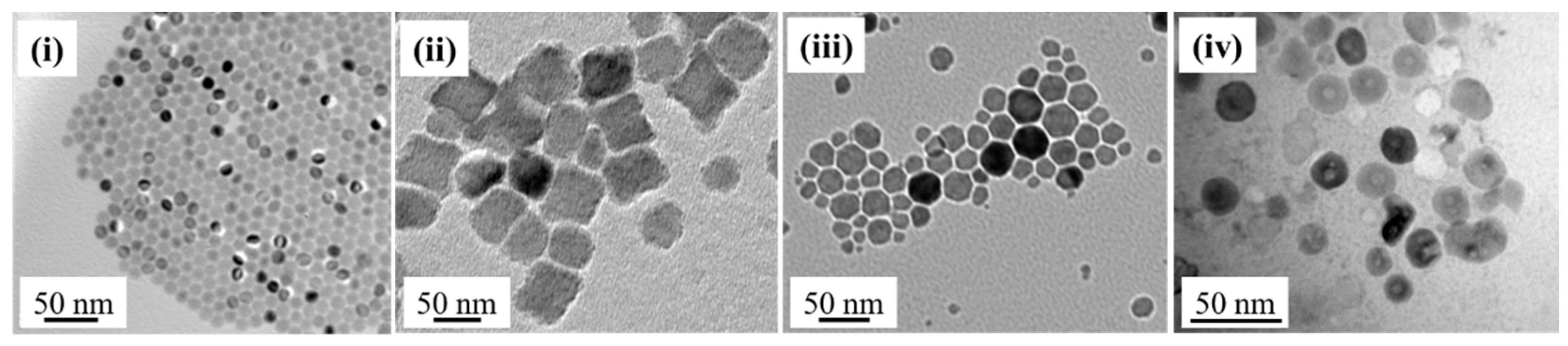
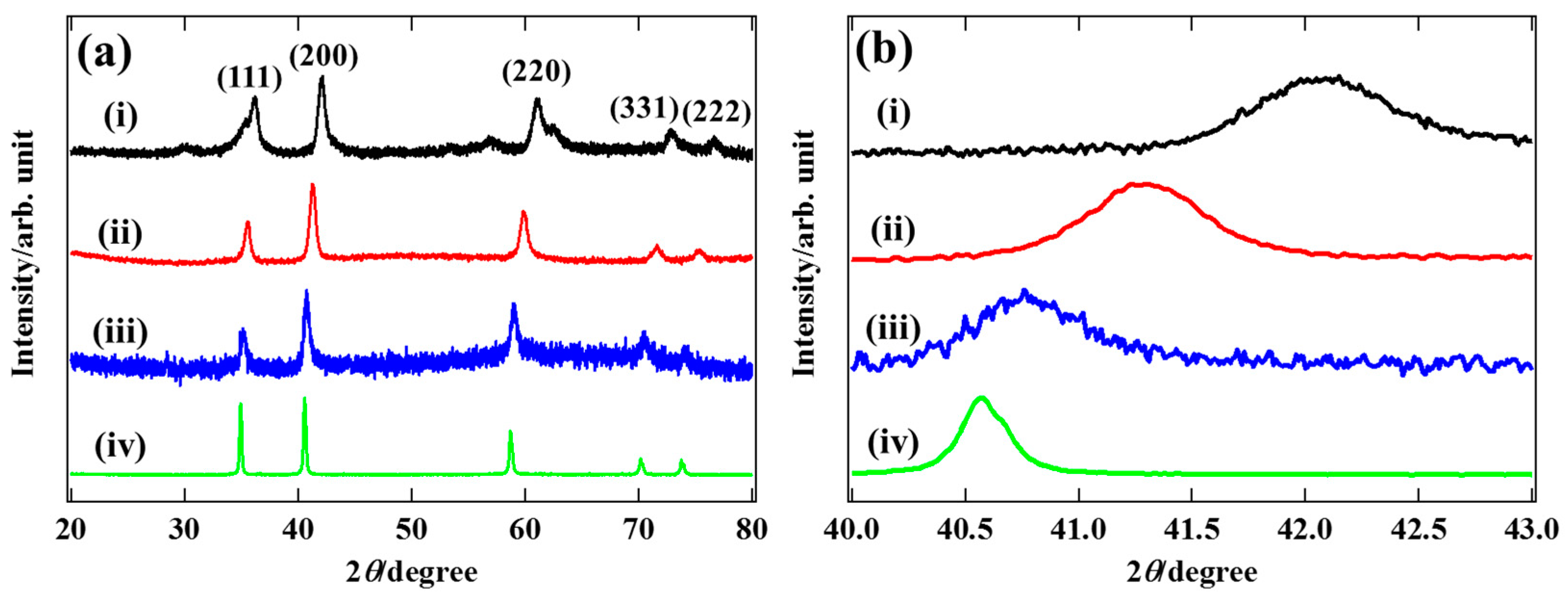
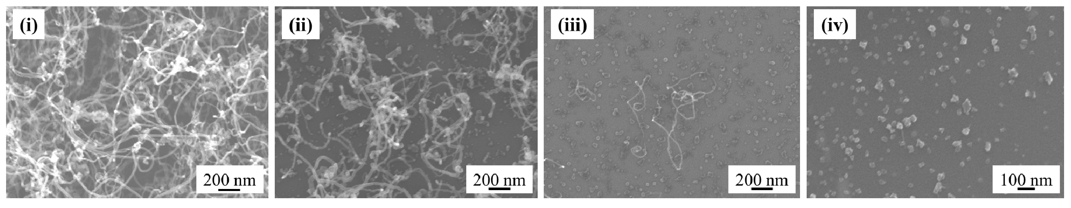
Figure 1. An electron diffraction pattern of the Fe nanoparticles after Plasma-enhanced chemical vapor deposition (PECVD). Inset shows the TEM image of nanoparticles attached to the carbon nanotubes (CNTs). Scale bar in the inset shows 100 nm.
Carbon 05 00046 g001
Figure 2. The surface morphology after the CNT growth with (a) and without (b) hydrogen treatment.
Carbon 05 00046 g002
Figure 3. Dispersity of the FeO nanoparticles on (a) an Al2O3/SiO2/Si substrate and (b) a SiO2/Si substrate.
Carbon 05 00046 g003
Figure 4. The surface morphology after the CNT growth (a) with Al2O3 layer and (b) without Al2O3 layer.
Carbon 05 00046 g004
Figure 5. TEM images of the Fe1−xMnxO nanoparticles with different composition ratio. (iiv) are as indicated in Table 1 that corresponds to different x in composition.
Carbon 05 00046 g005
Figure 6. (a) XRD patterns of nanoparticles. (b) Enlarged (200) peak to show the peak shift. (i)–(iv) are as indicated in Table 1.
Carbon 05 00046 g006
Figure 7. The surface morphology after the PECVD with different nanoparticle: (i) Fe (ii) Fe0.5Mn0.5 (iii) Fe0.9Mn0.1 (iv) Mn. The composition ratio is evaluated based on Vegard’s law.
Carbon 05 00046 g007
Figure 8. TEM images (a) and electron diffraction patterns (b) of CNTs grown with nanoparticles (i) and (ii).
Carbon 05 00046 g008
Figure 9. Raman spectra of the CNTs grown with (i) Fe nanoparticles and (ii) Fe0.5Mn0.5 nanoparticles. Inset shows the RBM of (i) in the range of 100–300 cm−1.
Carbon 05 00046 g009
Table 1. The ratio of acetylacetone complex in the source materials to prepare Fe1−xMnxO nanoparticles was shown in the first and second rows. acac stands for acetylacetone. The volumes of oleylamine and oleic acid (solvents) are both 5 mL. Chemical compositions evaluated by energy-dispersive X-ray spectroscopy and X-ray diffractionwere shown in the third row and fourth row, respectively.
Fe(acac)3/mmolMn(acac)3/mmolx by EDSx by XRD
(i)2.0000
(ii)1.01.00.50.5
(iii)0.171.80.970.9
(iv)02.011

