
Application of Patient-Specific Instrumentation in a Dog Model with Antebrachial Growth Deformity Using a 3-D Phantom Bone Model


Abstract
:1. Introduction
2. Materials and Methods
2.1. Case Selection
2.2. CT and Bone Image Segmentation
2.3. Preoperative Surgical Planning
2.4. Pre-Medication and Anesthesia
2.5. Surgery and Evaluation
2.6. Post-Operative Care
3. Results
4. Discussion
5. Conclusions
Author Contributions
Funding
Institutional Review Board Statement
Informed Consent Statement
Data Availability Statement
Acknowledgments
Conflicts of Interest
References
- Knapp, J.L.; Tomlinson, J.L.; Fox, D.B. Classification of Angular Limb Deformities Affecting the Canine Radius and Ulna Using the Center of Rotation of Angulation Method. Vet. Surg. 2016, 45, 295–302. [Google Scholar] [CrossRef] [PubMed]
- Johnson, J.A.; Austin, C.; Breur, G.J. Incidence of canine appendicular musculoskeletal disorders in 16 veterinary teaching hospitals from 1980 through 1989. Vet. Comp. Orthop. Traumatol. 1994, 7, 56–69. [Google Scholar] [CrossRef]
- Fox, D.B. Physeal injuries and angular limb deformities. Vet. Clin. N. Am. Small Anim. Pract. 2021, 51, 305–322. [Google Scholar] [CrossRef]
- Ramadan, R.; Vaughan, L. Premature closure of the distal ulnar growth plate in dogs—A review of 58 cases. J. Small Anim. Pract. 1978, 19, 647–667. [Google Scholar] [CrossRef]
- O’brien, T.R.; Morgan, J.P.; Suter, P. Epiphyseal plate injury in the dog: A radiographic study of growth disturbance in the forelimb. J. Small Anim. Pract. 1971, 12, 19–36. [Google Scholar] [CrossRef]
- Morgan, P.; Miller, C. Osteotomy for correction of premature growth plate closure in 24 dogs. Vet. Comp. Orthop. Traumatol. 1994, 7, 129–135. [Google Scholar]
- Henney, L.H.S.; Gambardella, P.C. Premature closure of the ulnar physis in the dog: A retrospective clinical study. J. Am. Anim. Hosp. Assoc. 1989, 25, 573–581. [Google Scholar]
- Fox, D.B.; Tomlinson, J.L.; Cook, J.L.; Breshears, L.M. Principles of uniapical and biapical radial deformity correction using dome osteotomies and the center of rotation of angulation methodology in dogs. Vet. Surg. 2006, 35, 67–77. [Google Scholar] [CrossRef]
- Nikolaou, C.; Black, C.; Ochoa, J.J.; Fitzpatrick, N. Guidelines for the Execution of True Spherical Osteotomies Using a Modified Dome Blade Design. Vet. Comp. Orthop. Traumatol. 2019, 33, 71–81. [Google Scholar] [CrossRef]
- Quinn, M.K.; Ehrhart, N.; Johnson, A.L.; Schaeffer, D.J. Realignment of the radius in canine antebrachial growth deformities treated with corrective osteotomy and bilateral (type II) external fixation. Vet. Surg. 2000, 29, 558–563. [Google Scholar] [CrossRef]
- Fox, S.; Bray, J.; Guerin, S.; Burbridge, H. Antebrachial deformities in the dog: Treatment with external fixation. J. Small Anim. Pract. 1995, 36, 315–320. [Google Scholar] [CrossRef] [PubMed]
- Harari, J. Complications of external skeletal fixation. The veterinary clinics of North America. Small Anim. Pract. 1992, 22, 99–107. [Google Scholar] [CrossRef]
- Green, S.A. Complications of external skeletal fixation. Clin. Orthop. Relat. Res. 1983, 180, 109–116. [Google Scholar] [CrossRef]
- Paley, D. Principles of Deformity Correction; Springer Science & Business Media: Berlin/Heidelberg, Germany, 2002. [Google Scholar]
- Arzi, B.; Cissell, D.D.; Pollard, R.E.; Verstraete, F.J. Regenerative approach to bilateral rostral mandibular reconstruction in a case series of dogs. Front. Vet. Sci. 2015, 2, 4. [Google Scholar] [CrossRef] [Green Version]
- Hespel, A.M.; Wilhite, R.; Hudson, J. Invited review-applications for 3D printers in veterinary medicine. Vet. Radiol. Ultrasound 2014, 55, 347–358. [Google Scholar] [CrossRef]
- Castilho, M.; Rodrigues, J.; Vorndran, E.; Gbureck, U.; Quental, C.; Folgado, J.; Fernandes, P.R. Computational design and fabrication of a novel bioresorbable cage for tibial tuberosity advancement application. J. Mech. Behav. Biomed. Mater. 2017, 65, 344–355. [Google Scholar] [CrossRef]
- Lee, H.-R.; Adam, G.O.; Yang, D.K.; Tungalag, T.; Lee, S.-J.; Kim, J.-S.; Kang, H.-S.; Kim, S.-J.; Kim, N.S. An Easy and Economical Way to Produce a Three-Dimensional Bone Phantom in a Dog with Antebrachial Deformities. Animals 2020, 10, 1445. [Google Scholar] [CrossRef]
- Fasanella, F.; Tomlinson, J.; Welihozkiy, A. Radiographic measurements of the axes and joint angles of the canine radius and ulna. Vet. Comp. Orthop. Traumatol. 2010, 23, A11. [Google Scholar]
- Jastifer, J.R.; Gustafson, P.A. Three-dimensional printing and surgical simulation for preoperative planning of deformity correction in foot and ankle surgery. J. Foot Ankle Surg. 2017, 56, 191–195. [Google Scholar] [CrossRef]
- Auricchio, F.; Marconi, S. 3D printing: Clinical applications in orthopaedics and traumatology. EFORT Open Rev. 2016, 1, 121–127. [Google Scholar] [CrossRef]
- Kwun, J.-D.; Kim, H.-J.; Park, J.; Park, I.-H.; Kyung, H.-S. Open wedge high tibial osteotomy using three-dimensional printed models: Experimental analysis using porcine bone. Knee 2017, 24, 16–22. [Google Scholar] [CrossRef] [PubMed]
- Balfour, R.J.; Boudrieau, R.J.; Gores, B.R. T-plate fixation of distal radial closing wedge osteotomies for the treatment of angular limb deformities in 18 dogs. Vet. Surg. 2000, 29, 207–217. [Google Scholar] [CrossRef] [PubMed]
- Dismukes, D.I.; Fox, D.B.; Tomlinson, J.L.; Essman, S.C. Use of radiographic measures and three-dimensional computed tomographic imaging in surgical correction of an antebrachial deformity in a dog. J. Am. Vet. Med. Assoc. 2008, 232, 68–73. [Google Scholar] [CrossRef]
- Morris, J.B. CAD/CAM options in dental implant treatment planning. J. Calif. Dent. Assoc. 2010, 38, 333–336. [Google Scholar] [PubMed]
- Martelli, N.; Serrano, C.; van den Brink, H.; Pineau, J.; Prognon, P.; Borget, I.; El Batti, S. Advantages and disadvantages of 3-dimensional printing in surgery: A systematic review. Surgery 2016, 159, 1485–1500. [Google Scholar] [CrossRef] [PubMed]
- Potamianos, P.; Amis, A.; Forester, A.; McGurk, M.; Bircher, M. Rapid prototyping for orthopaedic surgery. Proc. Inst. Mech. Eng. Part H J. Eng. Med. 1998, 212, 383–393. [Google Scholar] [CrossRef]
- Frame, M.; Huntley, J.S. Rapid prototyping in orthopaedic surgery: A user’s guide. Sci. World J. 2012, 2012, 838575. [Google Scholar] [CrossRef] [Green Version]
- Cartiaux, O.; Paul, L.; Francq, B.G.; Banse, X.; Docquier, P.L. Improved accuracy with 3D planning and patient-specific instruments during simulated pelvic bone tumor surgery. Ann. Biomed. Eng. 2014, 42, 205–213. [Google Scholar] [CrossRef]
- Meyer, D.C.; Siebenrock, K.A.; Schiele, B.; Gerber, C. A new methodology for the planning of single-cut corrective osteotomies of mal-aligned long bones. Clin. Biomech. 2005, 20, 223–227. [Google Scholar] [CrossRef]
- Michielsen, M.; Van Haver, A.; Bertrand, V.; Vanhees, M.; Verstreken, F. Corrective osteotomy of distal radius malunions using three-dimensional computer simulation and patient-specific guides to achieve anatomic reduction. Eur. J. Orthop. Surg. Traumatol. 2018, 28, 1531–1535. [Google Scholar] [CrossRef]
- Omori, S.; Murase, T.; Kataoka, T.; Kawanishi, Y.; Oura, K.; Miyake, J.; Tanaka, H.; Yoshikawa, H. Three-dimensional corrective osteotomy using a patient-specific osteotomy guide and bone plate based on a computer simulation system: Accuracy analysis in a cadaver study. Int. J. Med. Robot. Comput. Assist. Surg. 2014, 10, 196–202. [Google Scholar] [CrossRef] [PubMed]
- Omori, S.; Murase, T.; Oka, K.; Kawanishi, Y.; Oura, K.; Tanaka, H.; Yoshikawa, H. Postoperative accuracy analysis of three-dimensional corrective osteotomy for cubitus varus deformity with a custom-made surgical guide based on computer simulation. J. Shoulder Elb. Surg. 2015, 24, 242–249. [Google Scholar] [CrossRef] [PubMed] [Green Version]
- Murphy, S.B.; Kijewski, P.; Simon, S.; Chandler, H.; Griffin, P.; Reilly, D.; Penenberg, B.; Landy, M. Computer-aided simulation, analysis, and design in orthopedic surgery. Orthop. Clin. N. Am. 1986, 17, 637–649. [Google Scholar] [CrossRef]
- Webb, P. A review of rapid prototyping (RP) techniques in the medical and biomedical sector. J. Med. Eng. Technol. 2000, 24, 149–153. [Google Scholar] [CrossRef] [PubMed]
- Harrysson, O.L.; Cormier, D.R.; Marcellin-Little, D.J.; Jajal, K. Rapid prototyping for treatment of canine limb deformities. Rapid Prototyp. J. 2003, 9, 37–42. [Google Scholar] [CrossRef]
- Faber, J.; Berto, P.M.; Quaresma, M. Rapid prototyping as a tool for diagnosis and treatment planning for maxillary canine impaction. Am. J. Orthod. Dentofac. Orthop. 2006, 129, 583–589. [Google Scholar] [CrossRef]
- D’Urso, P.S.; Effeney, D.J.; Earwaker, W.J.; Barker, T.M.; Redmond, M.J.; Thompson, R.G.; Tomlinson, F.H. Custom cranioplasty using stereolithography and acrylic. Br. J. Plast. Surg. 2000, 53, 200–204. [Google Scholar] [CrossRef]
- Minns, R.; Bibb, R.; Banks, R.; Sutton, R. The use of a reconstructed three-dimensional solid model from CT to aid the surgical management of a total knee arthroplasty: A case study. Med. Eng. Phys. 2003, 25, 523–526. [Google Scholar] [CrossRef] [Green Version]
- Kim, M.S.; Hansgen, A.R.; Wink, O.; Quaife, R.A.; Carroll, J.D. Rapid prototyping: A new tool in understanding and treating structural heart disease. Circulation 2008, 117, 2388–2394. [Google Scholar] [CrossRef] [Green Version]
- Grujicic, A.; LaBerge, M.; Xie, X.; Arakere, G.; Pandurangan, B.; Grujicic, M.; Jeray, K.; Tanner, S. Computational investigation of the relative efficacies of nail-and plate-type proximal femoral-fracture fixation implants. Multidiscipline Model. Mater. Struct. 2011, 7, 212–244. [Google Scholar] [CrossRef]
- Ma, B.; Kunz, M.; Gammon, B.; Ellis, R.E.; Pichora, D.R. A laboratory comparison of computer navigation and individualized guides for distal radius osteotomy. Int. J. Comput. Assist. Radiol. Surg. 2014, 9, 713–724. [Google Scholar] [CrossRef] [PubMed]
- Soubeyrand, M.; Wassermann, V.; Hirsch, C.; Oberlin, C.; Gagey, O.; Dumontier, C. The middle radioulnar joint and triarticular forearm complex. J. Hand Surg. (Eur. Vol.) 2011, 36, 447–454. [Google Scholar] [CrossRef] [PubMed]
- Miyake, J.; Oka, K.; Kataoka, T.; Moritomo, H.; Sugamoto, K.; Murase, T. 3-dimensional deformity analysis of malunited forearm diaphyseal fractures. J. Hand Surg. 2013, 38, 1356–1365. [Google Scholar] [CrossRef] [PubMed]
- Tobias, K.M.; Johnston, S.A. Veterinary Surgery: Small Animal-E-BOOK: 2-Volume Set; Elsevier Health Sciences: Amsterdam, The Netherlands, 2013. [Google Scholar]


| Golden Retrievers | Mean Value | Reference Value | |
|---|---|---|---|
| Frontal | aMPRA | 83 | 82~83 |
| aLDRA | 86 | 85~87 | |
| Sagittal | aCdPRA | 85 | 84~86 |
| aCdDRA | 77 | 76~78 | |
| Θ | 27 | 21~32 | |
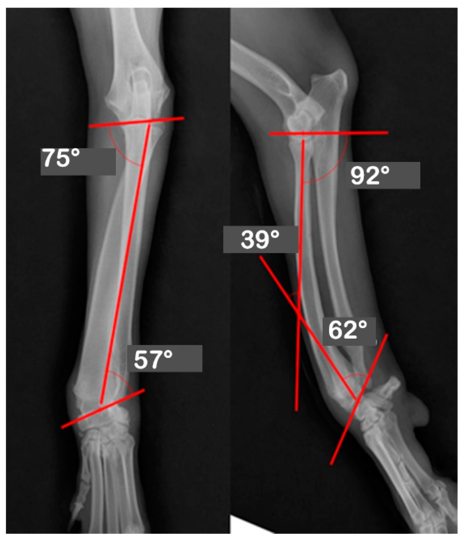
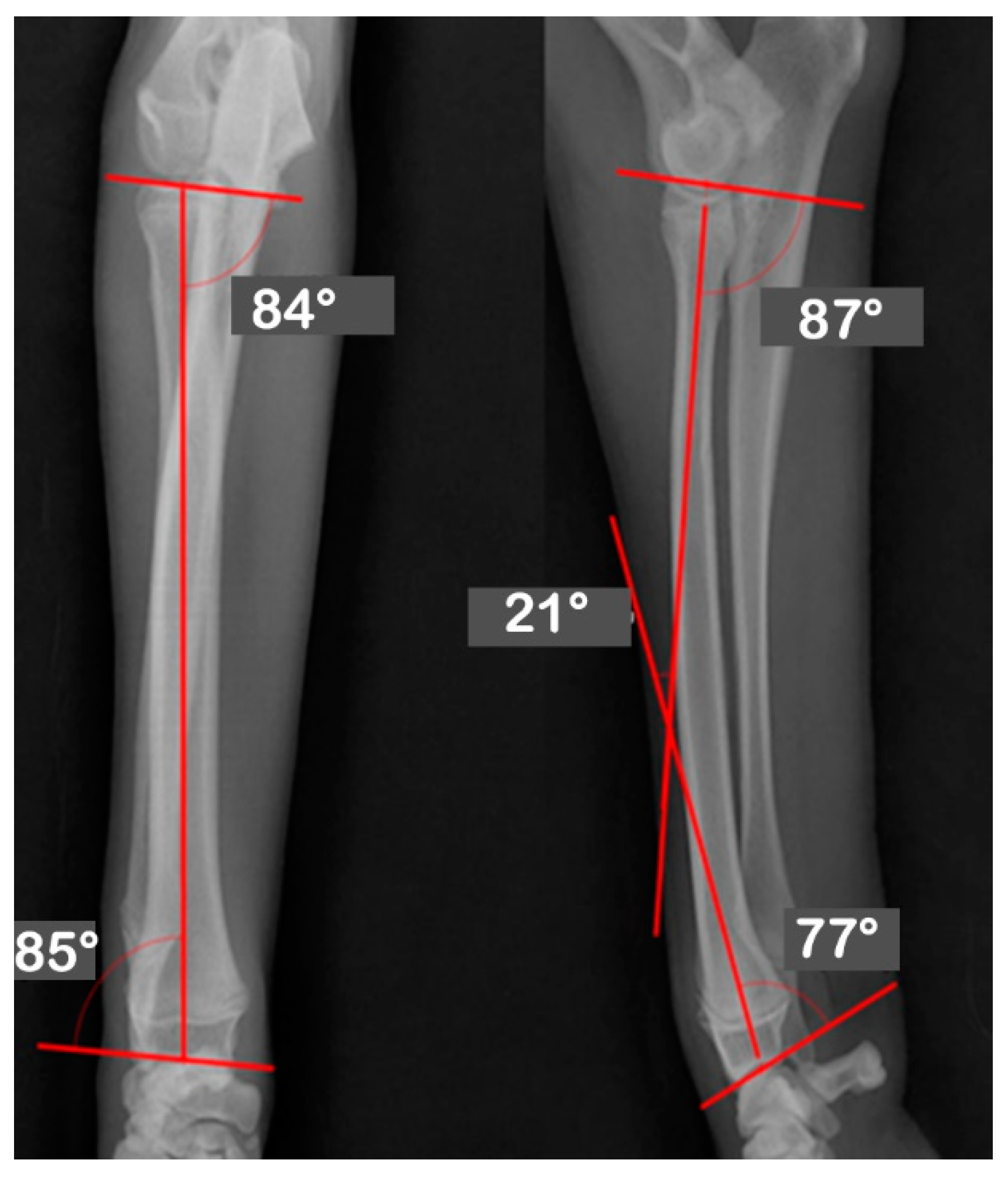
| JOA | Pre-OP | Post-OP | Target | Mean | Reference |
|---|---|---|---|---|---|
| Values | Values | ||||
| aLDRA | 57 | 85 | 85 | 86 | 85~87 |
| aCdPRA | 92 | 87 | 87 | 85 | 84~86 |
| aMPRA | 75 | 84 | 84 | 83 | 82~83 |
| aCdDRA | 62 | 77 | 77 | 77 | 76~78 |
| θ | 38 | 21 | 21 | 27 | 21~32 |
Publisher’s Note: MDPI stays neutral with regard to jurisdictional claims in published maps and institutional affiliations. |
© 2022 by the authors. Licensee MDPI, Basel, Switzerland. This article is an open access article distributed under the terms and conditions of the Creative Commons Attribution (CC BY) license (https://creativecommons.org/licenses/by/4.0/).
Share and Cite
Lee, H.-R.; Adam, G.O.; Kim, S.-J. Application of Patient-Specific Instrumentation in a Dog Model with Antebrachial Growth Deformity Using a 3-D Phantom Bone Model. Vet. Sci. 2022, 9, 157. https://doi.org/10.3390/vetsci9040157
Lee H-R, Adam GO, Kim S-J. Application of Patient-Specific Instrumentation in a Dog Model with Antebrachial Growth Deformity Using a 3-D Phantom Bone Model. Veterinary Sciences. 2022; 9(4):157. https://doi.org/10.3390/vetsci9040157
Chicago/Turabian StyleLee, Hee-Ryung, Gareeballah Osman Adam, and Shang-Jin Kim. 2022. "Application of Patient-Specific Instrumentation in a Dog Model with Antebrachial Growth Deformity Using a 3-D Phantom Bone Model" Veterinary Sciences 9, no. 4: 157. https://doi.org/10.3390/vetsci9040157