Review

MatriGrid® Based Biological Morphologies: Tools for 3D Cell Culturing

1
Department of Nano-Biosystems Engineering, Institute of Chemistry and Biotechnology, Ilmenau University of Technology, 98693 Ilmenau, Germany
2
Placenta Lab, Department of Obstetrics, Jena University Hospital, 07747 Jena, Germany
3
Biophysics Division, GSI Helmholtzzentrum für Schwerionenforschung, 64291 Darmstadt, Germany
4
Institute of Environmental Toxicology, Martin-Luther-University Halle-Wittenberg, 06097 Halle, Germany
*
Authors to whom correspondence should be addressed.
These authors contributed equally to this work.
Current address: Lonza AG, Quality Control Microbiology—Cleaning Validation, 3930 Visp, Switzerland.
§
Current address: Department of Bioelectronics (BEL), MINES Saint-Étienne, CEDEX 2, 42023 Saint-Étienne, France.
Bioengineering 2022, 9(5), 220; https://doi.org/10.3390/bioengineering9050220
Submission received: 8 April 2022 / Revised: 6 May 2022 / Accepted: 11 May 2022 / Published: 20 May 2022
(This article belongs to the Special Issue Analytical Approaches in 3D in vitro Systems)

Abstract

:
Recent trends in 3D cell culturing has placed organotypic tissue models at another level. Now, not only is the microenvironment at the cynosure of this research, but rather, microscopic geometrical parameters are also decisive for mimicking a tissue model. Over the years, technologies such as micromachining, 3D printing, and hydrogels are making the foundation of this field. However, mimicking the topography of a particular tissue-relevant substrate can be achieved relatively simply with so-called template or morphology transfer techniques. Over the last 15 years, in one such research venture, we have been investigating a micro thermoforming technique as a facile tool for generating bioinspired topographies. We call them MatriGrid®s. In this research account, we summarize our learning outcome from this technique in terms of the influence of 3D micro morphologies on different cell cultures that we have tested in our laboratory. An integral part of this research is the evolution of unavoidable aspects such as possible label-free sensing and fluidic automatization. The development in the research field is also documented in this account.

1. Introduction

A continuously rising number of literature sources claiming the similarities of 3D cell culturing to in vivo data shows the self-depicting importance of mimicking the three-dimensional microenvironment for cell culture [1]. The topic of 3D cell culturing featuring different aspects of their advantages is excellently reviewed [2,3,4]. The design and construction of oligocellular agglomerates or embroid bodies, such as cell aggregates or tissue-like oligocellular structures, are driven by different biological and technological trends in stem cell research [5]. Various techniques, such as 3D bioprinting [6], micromachining [7], hydrogel assembly [8], and microfluidics [9], are being developed day by day to obtain better ECM materials. Microfluidic approaches such as the hanging drop method [10] have led to embroid bodies as a starting point for the evolution of organoids, whereas 3D bioprinting with different types of cells embedded in, e.g., a bio ink as a type of scaffold-based approach is another way to come to organ-like structures [11]. Many of these techniques use gel-based approaches, which often vary in their composition and additionally limit the nutrient and oxygen supply [12]; therefore, more and more gel-free systems, such as anchorage-dependent cell culture [13], fiber-based scaffolds (either electro spun [14] or hollow fibers [15]), hanging drop culture [16,17], dielectrophoresis [18], micropillar [19], 2PP fabricated scaffolds [20,21], and microwell 3D culture [22], are in demand.
The hanging drop culture is perhaps the most widely used 3D cell culture method because it produces spheroids with uniform morphology; the operation is convenient and low cost. However, the workload is significant, and the high throughput operation is difficult to achieve. Efforts to resolve these disadvantages have resulted in commercial hanging drop plates in 96- and 384-well formats [23,24]. A. Ganguli et al. developed a silicon-based hanging drop microarray suitable for high throughput applications and compatible with high-resolution confocal microscopy [25]. A new hanging drop approach for producing consistent droplet volume was created by combining the hanging drop array with a fluidic system [26]. Consistent droplet volume is achieved by the spontaneously pulling of the cell suspension toward an internal chamber, which is caused by the pressure difference across the hanging drop array. A perfused hanging drop array based on a PMMA microfluidic chip was developed by Shu-Wei Huang et al. [27]. The chip design uses taper tubes for increased droplet stability and an enhanced liquid exchange rate.
In a comparative study, two cancer cell lines, MCF7 and OVCAR8, were used to grow spheroids using three different methods: the hanging drop plate, liquid overlay on an ultra-low attachment (ULA) plate, and liquid overlay on a ULA plate with rotating mixing [28]. The last method produced significantly more chemoresistant spheroids with higher amounts of deposited extracellular matrix.
Additionally, bottomless well plates are used for the hanging drop technique to form a droplet of medium within each well that is big enough for cells to aggregate but small enough to not fall off while cultured [4].
Other techniques to generate such self-assembled cell aggregates (spheroids) include low adhesion plates, v-shaped plates, and magnetic cell levitation [4,29]. The advantage of low adhesion plates or v-shaped plates compared to hanging drop plates is the avoidance of transfer of spheroids after their formation to a different plate for further culturing or experiments as these plates have a larger volume. Cell aggregation is prevented by using polystyrene plates that are treated with hydrophilic or hydrophobic coatings such as the non-adherent polymer poly-HEMA [30] or natural polymers such as agarose [31]. A new complex technique for generating spheroids is magnetic cell levitation. In this technique, cells are loaded with magnetic nanoparticles and levitated towards the air–liquid interface using a magnetic field. Magnetic cell levitation has been successfully used to produce monocellular and multicellular spheroids [32,33,34,35,36].
Compared to the spheroid building technique, culturing cells in 3D microcontainers brings the additional advantage of restricting the culture to growth within particular geometrical and biochemical boundaries. These, in turn, affect the cellular behavior of organoid cell culture. There is no doubt that all these features and parameters play an important role in the understanding (and the redesign) of biological systems. Higher macroscopic organisms consist of biological components on the microscale and nanoscale, so the starting point in this analysis is to consider all the geometric scales involved in the system. We have introduced the term “biotechnical multiscale engineering” for a methodological approach to designing artificial hybrids of biological and technological systems [37]. Hereby, many biological systems are analyzed, ranging from the sub-nanometer elements such as cell adhesion molecules to micron-sized capillaries and the macroscopic dimensions and functionality of whole organs. Thus, for better control over culturing space, shape, diffusion parameters, and imaging, transparent thermoplastics such as polycarbonate (PC) [38,39], poly methyl methacrylate (PMMA) [40,41,42], polystyrene (PS) [43], and cyclic olefin polymers or copolymers (COP/COC) [44,45] are being explored. The general resistance of thermoplastics toward changes in temperature, pressure, and high chemical stability makes them ideal for mass production [46].
Based on the idea that each specific organ-like cell agglomerate also needs a specific geometrical shape, we have developed tools and techniques for the construction of a family of polycarbonate substrate scaffolds that we call MatriGrid®s. These scaffolds are suitable not only for cell culturing but also for the manipulation and evolution of embroid bodies, for mimicking stem cell niches, or for control of the behavior of tissue slices. Some of these scaffold-based approaches use polymeric scaffolds for shaping the evolving oligocellular agglomerates. Scaffold-based approaches allow us not only to define the shape of the agglomerates but also to control biophysical and mechanical properties such as stiffness, shear stress, and nutritious flow if integrated into lab-on-a-chip devices or bioreactors [47].
The technique is based on template or morphology transfer technology, where the forming of thermoplastic (bio)-polymers allows us to design some complex geometries. This opens promising perspectives for the mimicking and bio-fabrication of free-form complex morphologies for the construction of more native and tissue-like microarchitectures [37] or manipulation tools [48]. This toolbox also includes methods of micrometer-scale biochemical or topographical patterning, which are commonly used to guide cell attachment and growth. By use of our advanced 3D microcontact printing (3DμCP) [49], predesigned microstructures can be fabricated. This includes fluidic channels with different depths and widths that contain biochemical cues or even more complex patterns.
Recently, we described a good example of the biotechnical multiscaling approach using template transfer technology by biomimetic reconstruction of the hematopoietic stem cell niche for in vitro amplification of human hematopoietic stem cells [50,51,52]. The main geometric features of a microtome intersection from the bone marrow (BM) of a human long bone were retrieved by image processing. The extracted features were adapted to construct photolithographic masks. This way, tools and molds for polymeric reproduction were designed (following the structure replication in different polymeric embodiments on an MTP footprint) and, finally, used for cell amplification experiments [50,51].
Apart from the scaffold design, organized fluidics is the most demanding part of such complex organotypic 3D models. Unlike a conventional cell culture, a special readout mechanism is required for the qualification of the culture parameters without manual intervention in mostly static and passive fluidics [53,54,55]. A big improvement is the dynamic (perfused) fluidic systems, with possibilities to enhance nutrition and metabolite transport in 3D cell culture [56,57,58]. It is also known that the flow direction has a significant influence on cell proliferation, which ultimately guides vascularization [59,60,61]. Furthermore, in a recent study of 3D MatriGrid® environments (static and perfused) for the culturing of neuroblastoma cancer cells, this was analyzed in detail and compared with neuroblastoma tissues and 2D culture, showing that anti-cancer drug treatments in 3D are closer to the real-world situation than a 2D culture [62]. In perfused culture systems for long-term experiments, it is desirable that the necessary media exchange and the sampling of probes for analytics are carried out in an automated way.
What is needed for analytical approaches for 3D in vitro systems? First of all, devices/scaffolds that bring the cells into a 3D shape and behavior. Second, the devices in which such scaffolds with the cell agglomerates are preferably handled. Third, an open interface to all traditional laboratory equipment, with the possibility of easily transferring the scaffolds to readers, microscopes, analytical devices, etc. It would also be desirable to integrate analytical functionality directly into the 3D cell culture devices, but this would result in complicated lab-on-chip experimental setups. Although they might be very fruitful, such solutions would still be expensive and not standardized in biological medicinal laboratories. In a parallel paper in this issue, we described a case study for such an integrated approach of a flow-through ELISA, together with our automatic bioreactor unit, based on commercially available components.
In the following sections, we describe our tools, techniques, and designs, with selected technical and biological examples, that use different polymeric scaffolds with adapted geometry and patterning to meet the 3D cell culture requirements for individual organs.
In the first part, we give an overview of the MatriGrid® scaffold family and describe the scaffolding techniques based on thermoforming tools, together with methods for functionalizing such substrates. In the following chapter, we introduce tools for fluidics and analytics, such as the microbioreactor device, the 3D-MEA device (for measuring electroactive neuronal cell agglomerates), and the automatic sampling drug application unit. Then, we report different species of MatriGrid®s with their morphology, function, and biological results. The following section describes the long-term measurements of the hepatic cell culture and the biological results achieved. We close the description of our account of research with a classification with respect to contextualization and a discussion of further perspectives of technological development.

2. Overview

Advanced cell culturing technologies should not only fulfill the demand of oligocellular cell populations, such as in real organs, but they should also meet physical, engineering, and economic aspects to make them suitable for a wide range of applications. However, many advanced cell culturing approaches developed in the past have maintained their individual and different characteristics [63]. Therefore, for scaffold-based 3D culturing devices, we consider the following engineering constraints and conditions desirable:
  • All the scaffolds and scaffold holders should be compatible with the MTP footprint to support laboratory automation standards.
  • Scaffold production should allow cost-efficient mass production.
  • Scaffold production should be scalable with respect to morphology and design (e.g., pore size).
  • If required, it should be possible to introduce and modify pores and channels specifically in order to achieve high diffusion gradients, flow-through, or active material transport.
  • For the devices adopting MTP and other footprints, compatibility with common laboratory equipment should be preferred as much as possible. This means that wherever possible, an open interface to readers, microscopes, etc., should be chosen. This includes aspects such as easy transfer, easy handling of covers, transparency of material, etc.
  • The platform design should be modular, and the building blocks should be able to connect to each other; for example:
    Possibility of stacking scaffolds in an MTP well or in a microbioreactor.
    Possibility of cascading single-unit micro bioreactors with optional fluid addition, e.g., to make drug administration or dilution of metabolic products possible.
Nevertheless, we were seeking a general method that could offer a feasible and rapid technique with the potential of integrating most of the information, data, and parameters in the field of advanced cell culturing systems. It is surely difficult to meet all biological, geometrical, and physiological constraints within a single approach. To make it more feasible from the (bio)-physical point of view, one should confine the limits of a system to particular characteristics.
We have chosen geometrical aspects of an organ as a major boundary condition because it can offer cellular confinement relevant to its native tissue. For example, in order to mimic the geometrical aspects of a liver-like advanced cell culture system, a cell culture medium flow rate of approximately 20 µL/min is required to adequately supply a liver lobule (approx. 2 × 10⁵ cells) with oxygen. This value is derived from the oxygen demand of the cells. For a 3D cell cluster, the maximum size that can be supplied by diffusion is approx. 300 µm (see Supplementary Information: O2 consumption of a liver lobule).
The same line of engineering arguments could be held for every native tissue model. From our point of view, aiming mainly for the geometrical aspect of different organs is mimicked easily by 3D microstructured morphologies, which have high chances for cost-effective production by template transfer technologies and, in turn, can facilitate the widespread utilization of native-tissue-inspired morphologies in science and industry. Based on our research philosophy, various geometrical approaches constrained to individual organs are shown in Figure 1.
As depicted in Figure 1, in principle, it is possible to mimic the geometrical aspects of almost every tissue. However, it might be misleading to generally compare advanced cell culturing systems using different approaches, materials, and techniques. There might be advantages of one system that can overcome another. If we focus, for example, on liver cell culture, for which there are, to date, well-explored advanced cell culturing systems, one can witness the relative and complimentary advantages of each system with respect to one another (see Table 1). In the following section, our approach to mimicking various tissue morphologies is explained.

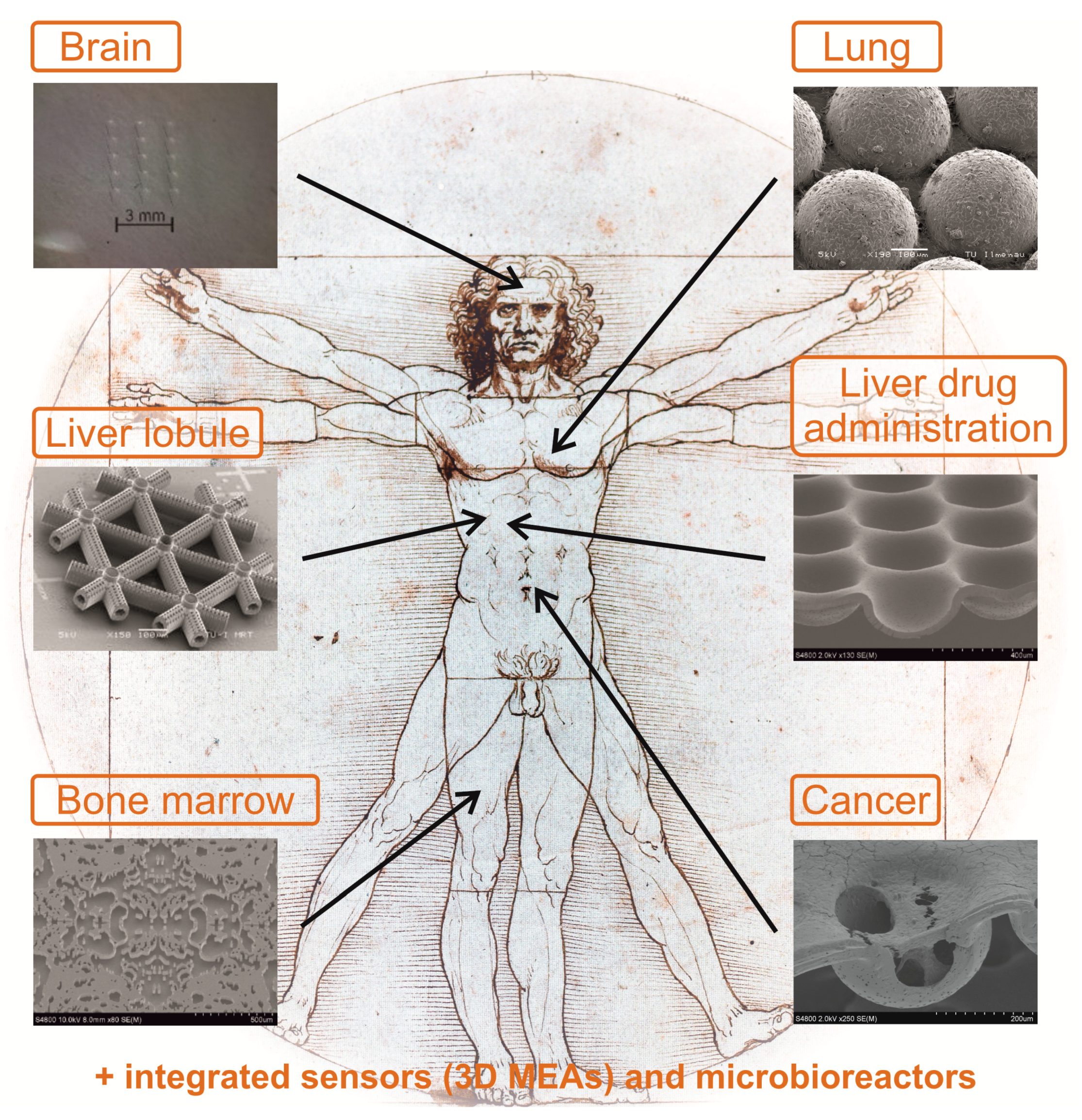
The MatriGrid®-Family—Overview

Three-dimensional (3D) cell cultures are becoming increasingly important as this method of cell culturing better mimics tissue physiology in multicellular organisms [84]. The 3D cell cultures can be classified according to scaffold-free and scaffold-based systems [84]. In scaffold-free 3D cell cultures, single cells are seeded in suspension culture. By preventing the cells from adhering to the walls of the cell culture vessel, the cells combine to form multicellular aggregates. These cell aggregates, formed by self-assembly, are commonly referred to as spheroids [85]. Spheroids have a variety of properties, such as ideal physiological cell–cell interactions, the formation of their own extracellular matrix (ECM) components, and better cell–ECM interactions [86]. On the other hand, organoids can be distinguished if 3D cell cultures from embryonic or primary stem cells, as well as primary tissue, show organ functions after self-assembly [87].
On the other hand, in scaffold-based 3D cell cultures, the cells are embedded in a matrix, and the properties of the cells growing there are determined by the chemical and physical properties of the scaffold itself. The scaffolds are designed to promote cell adhesion and cell–cell and cell–matrix interactions. Furthermore, adequate transport of nutrients and gases should be enabled to support cell growth and avoid toxicity [88]. In addition, 3D structures facilitate tissue-specific differentiation [89]. Technically, scaffold-based 3D cell cultures can be based on soft hydrogel or solid polymer structures. A variety of natural (fibrin, collagen, hyaluronic acid, silk, and gelatin) and synthetic (synthetic polymers, titanium, bioactive glasses, and peptides) materials are used as soft scaffolds, which are manufactured using nearly equal large numbers of manufacturing processes. On the other hand, polymer-based solid scaffolds have proven to be particularly suitable due to their properties, such as high porosity, small pore sizes, biodegradability, and mechanical properties [84]. Solid-scaffold-based 3D cell culturing systems provide mechanical support to the cells growing in a 3D environment, due to which the cellular outcome of such cultures is closer to the in vivo situation. Our research group has focused on polymer-based 3D scaffolds, tuned through the mentioned micro thermoforming technique that is described in detail in the following chapter. The tools and materials that the micro thermoforming technique depends on provide nearly unlimited possibilities to construct geometries of various designs, ranging from simple micro containers to complex bio-mimicking topographies.
The first ideas of scaffold-based containers for cell culturing were guided by the philosophy of forcing the cells to grow in a 3D manner or forming intercellular 3D contacts defined by the geometric shape in such a way that the cells inside the cell agglomerates would not become necrotic [90,91,92]. This was achieved by selecting proper scaffold geometry with dimensions that allowed nutritious supply to the cells by diffusion or perfusion through porous scaffold structures. In both cases, this may be implemented either by active fluidics or passive means, such as the diffusion or convection of the media. One has to consider not only the biophysical constraints but also the given technical limits of the physical properties of the material, micromachining, and tooling. In principle, with micro thermoforming technology, microstructures with dimensions down to 10 µm are feasible. However, it depends upon the specific structure and thickness of the source material. For example, in the case of MatriGrid®, 50 µm thick foil was stretched into a micro mold up to 300 µm depth. Beyond these dimensions, the cavities will rupture due to the lack of material strength. Therefore, the first MatriGrid® design was constructed as a scaffold with defined porous and non-porous regions, which allowed a controlled flow of the media through a 3D culture of pure hepatic cells [37,93,94,95]. Further development and applications are also possible by applying oligocellular cell mixtures in such a cavity; for instance, applications to cancer research have become possible [62].
Another idea is to mimic the real fluidic structure of an organ and then guide the different cell species to the right place on the scaffold for adhesion. The structures of MatriGrid®s are modeled according to the functional units of respective organs and their specific geometrical characteristics (biotechnical multiscale engineering) [20]. Using this idea, the first MatriGrid® design was created for directed oligocellular cultures, which was inspired by the morphology of the lung [96,97]. Following the idea of constructing real geometric environments for cell culturing, we developed a scaffold for mimicking the blood stem niche in bone marrow, which we call BMGrid® [50,51,52]. Similarly, to develop MatriGrid® for growing neurons, we evolved our micro-container-based scaffold into specialized linear structures for the growth and handling of neurons and spheroids. In another study, a line- and space-based 3D scaffold was developed to roughly mimic capillary structures as a base to approach the morphology of a liver lobule [98].
In the following section, we describe the learning outcome from the MatriGrid® scaffold family: MatriGrid® with applications to liver cells and the oligocellular lung alveoli model, NeuroGrid® for application to neuronal cells, and TissGrid® for application to placenta explants.

3. Micro Thermoforming and Functionalization of MatriGrid®s

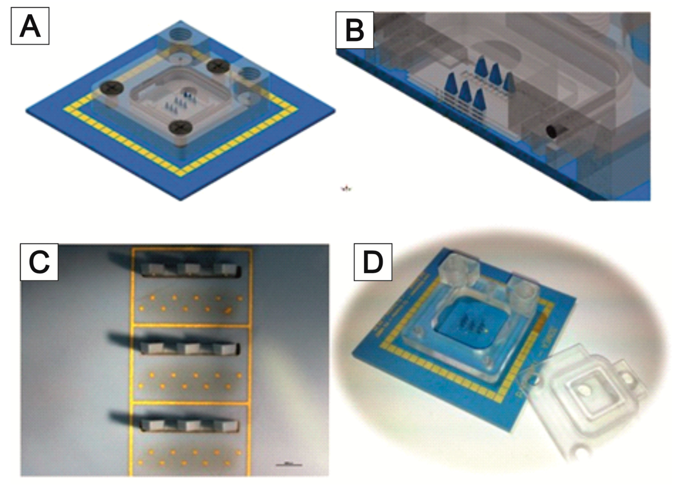
3.1. Micro Thermoforming

Most polymeric scaffolds are accessible through microscopical assessment, which makes them advantageous to inorganic/organic scaffolds or scaffolds derived from hydrogels. In addition, they are compatible with a wide range of processing technologies that provide access to low-cost production. Polymeric foils are also suitable for thermoforming; therefore, they are an attractive raw material for manufacturing polymeric 3D cell culturing scaffolds. For biological applications in cell culture, the scaffolds need to have accurate and reproducible properties; otherwise, experimental results are hardly comparable or even meaningless. Porous membranes offer advanced functionalities as they allow for the continuous perfusion of the cells through the scaffold’s micro pores, leading to an enhanced supply of nutrients and oxygen. In the following chapters, various selected scaffolds and their applications are presented, which were basically produced by the technology described below.
The micro thermoforming technology presented here produces reproducible scaffolds with precisely defined properties. Due to the single-stage manufacturing process, efficient production of scaffolds is possible through parallelization. To ensure the high homogeneity of the scaffolds, aspects of permanent quality control have been integrated. However, a major disadvantage of the ordinary thermoforming process is the inability to form porous materials due to pressure equalization through the pores during the processing of the material. This disadvantage can be overcome by adding an additional, non-porous support film that transfers the forming pressure to the porous film under isostatic conditions. In this process, a so-called polymer sandwich is formed. This one-step process results in the effective and parallel production of scaffolds with precisely defined and reproducible properties [99]. The carrier film can then be easily removed from the structured porous membrane. Boundary conditions for the production of the sandwich are the result of the forming temperature of the porous membrane, the material composition of the sandwich, and the thickness of the two films to ensure an optimal working process. A thermoforming machine (Wickert presstech, 76829 Landau i.d.Pf., Germany) specially designed for this application provides both vacuum and high pressure by means of integrated pumps and compressors. All these modules are integrated into the compact housing of the machine.
Separation of the heating and cooling plates by a two-stage mold design enables fast process sequences. Until the film stack is pressure-loaded, the heating plates are separated from the cooling block by insulated springs and guide rails. The cooling block is made of aluminum, which has a large heat capacity compared to the heating plate. The thin but rigid heating plate is made of special tool steel with a high elongation at break. Before the gas pressure is applied, the press closes the remaining 1 mm gap between the cooling block and the heating plate. Now, a counterforce to the gas pressure can be built up. This counterforce can be adjusted by varying the gas pressure. Guide blocks were mounted to align the heating plate and cooling block and to allow for different thermal expansions of the materials used. This setup provides good mold guidance and short cycle times. Figure 2 shows a scheme with a description of the manufacturing steps, used tools, and fabricated scaffold.
Isostatic molding technology has many advantages, such as uniform force distribution, easy force generation, and independence from the wedge error of the two sides of the tool. Tools can be made not only from a variety of established materials (e.g., metal, ceramics, semiconductors, or plastics), but it is also possible to use soft materials as tool dies [100]. Tools can thus be manufactured by a variety of manufacturing processes. Examples are conventional processes such as milling and EDM, but etching techniques used in microstructuring and rapid prototyping technologies can also be used.
A disadvantage is that the technique is mainly used to form thin materials. The isostatic principle is also disadvantageous in the forming of porous materials due to the use of a fluid as a force transmitter. The applied fluid pressure would immediately penetrate the membrane, depending on the pore geometry and the parameters of the fluid. Thus, the mapping of the mold geometry would no longer be possible.
In principle, there are two basic ways to process yet-porous substrates by thermoforming. One established method, as described above, is to use a transfer membrane. It allows the direct use of the porous film. A novel method was demonstrated by Giselbrecht et al., who processed films prepared before ion irradiation by thermoforming [92]. Later, the formed structures were etched to obtain porous microstructures. The advantage of this method is the ease of process adjustment.
One problem with this method is the annealing of the pre-irradiated ion tracks due to the thermal effects during the heating and cooling cycle. A detailed description of the annealing process can be found in Skehon et al. [101]. This leads to an uneven pore geometry. Recent research shows the appearance of membrane-like structures in the center of the holes, so-called apertures, as a result of the annealing of the ion tracks. These act like bottlenecks and increase the flow resistance of the entire pore enormously. Figure 3A,B show a comparison of healed and native porous PC film. Healing occurred after processing the film, according to the time scale that is standard for modified embossing machines.
Afterward, the film can be made porous by etching under alkaline conditions. Compared to the native and untreated film, the membrane with previous heat treatment shows a centered constriction in the etched pore. The heat treatment is a part of the thermoforming process in which the film is heated from room temperature to forming temperature (about 160 °C for polycarbonate), formed, and then cooled down to room temperature in a few minutes. This cycle time is caused by the large thermal mass of the heating plates in a conventional embossing machine. Additionally, the installed heating power is small compared to the mass of the heating plate. Due to these process-related limitations, the flow resistance of the foil increases enormously. Unfortunately, such defects are not visible during optical microscopy inspection of the transparent foil and can only be investigated using SEM images and cross-sections. To overcome this disadvantage, design and technological efforts must be taken to shorten the cycle times. Figure 3C shows an etched film with a short heat treatment before etching, according to the method described earlier and seen in Figure 2. Here, no annealing of the ion tracks can be seen due to the short cycle times. It illustrates the need for fully integrated and adapted processing of these special films with tailored thermoforming technology. Depending on the compact and robust machine design, mold design, and geometry, the heat treatment during the process significantly influences the manufacturing results. The polymers provide a good opportunity for additional treatment. Shaped polymers can be coated by ECM material or functionalized by chemical methods.

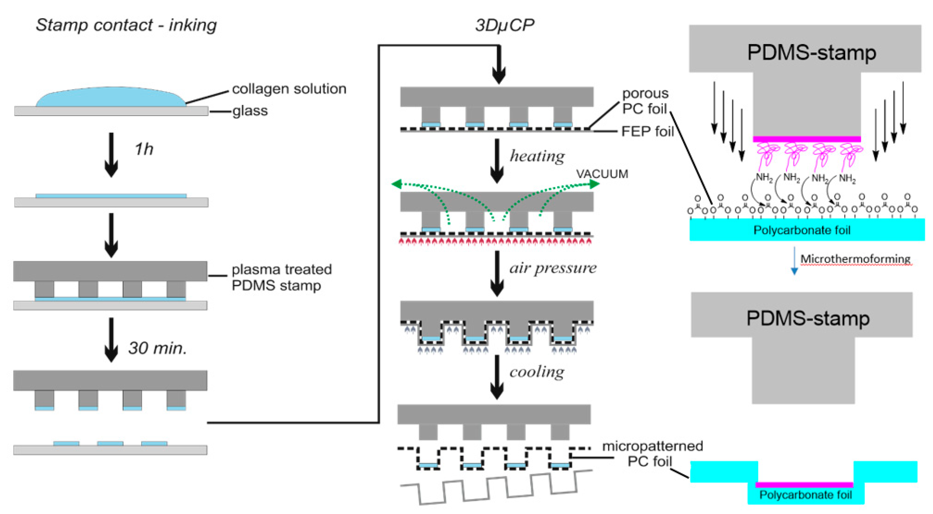
3.2. Microcontact Printing and Chemical Functionalization

Microcontact printing has proved to be a facile technique for patterned cell growth [102]. However, with the present microcontact printing techniques, there is no provision to create microscopic geometrical barriers along with chemical patterning. In other words, technical means of transferring biochemical molecules to the pre-structured micro geometries in a precise, reproducible, and high-throughput manner are limited [103,104,105]. Therefore, the applicability of conventional microcontact printing remains restricted when complex 3D surfaces, e.g., channels or tubular structures with defined chemical and topographical micropatterns, are desirable [103].
We have developed a 3-dimensional microcontact printing (3D µCP) technique within the context of thermoforming that is capable of structuring microtopographies on the surface and the precise transfer of the extracellular matrix (ECM) proteins into the obtained geometries simultaneously [49]. By combining the advantages of microcontact printing with microthermoforming to synchronize the chemical and topological patterning in one step, the extension of the scope of 2D surface patterning to the 3D surface is possible. Conventional stamps made from polydimethylsiloxane (PDMS) [106] can be used. In brief, a stamp with a target pattern was selectively inked with biomolecules and subsequently used as a mold for microthermoforming. Therefore, microstructuring and chemical patterning could be performed at the same time. During thermoforming, a polymer film is heated up to the thermoplastic state and formed under gas pressure onto a mold to replicate its topography [107]. Microthermoforming is highly reproducible, efficient for mass production, and works for most thermoplastics polymers, including biodegradable polymers used in tissue engineering as well as porous and permeable polymer films [108]. We chose polycarbonate membranes as a substrate because they are commonly used for cell culture applications, are highly transparent, and are available in different thicknesses and pore sizes [109]. Our process has been validated by microscopic measurements and fluorescence staining.
Among the various polymeric materials explored for solid 3D scaffold formation, polycarbonate is prominently suitable for thermoforming applications. Even in the case of 3D microcontact printing, it has a good chemical affinity to biopolymers such as collagen. The most probable reason for the chemical binding of the amine-containing biopolymers with polycarbonate is carbamate formation (Figure 4). Inspired by the tendency of covalent bond formation between amine and carbonate, we explored various terminal diamines and polyamines [110] to chemically functionalize the polycarbonate surface. Even the post thermoforming functionalization of polycarbonate surface was stable under cell culture conditions. Such aminized polycarbonate surfaces were explored to attach biologically interesting molecules and dyes [110]. Even photochromic dyes such as donor-acceptor Stenhouse adducts were explored as visible-light-assisted photoswitches on polycarbonate surfaces [111,112].

4. Tools for Fluidics and Analytics—The Bioreactors
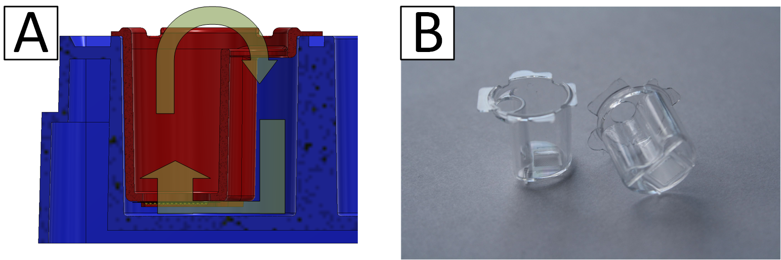
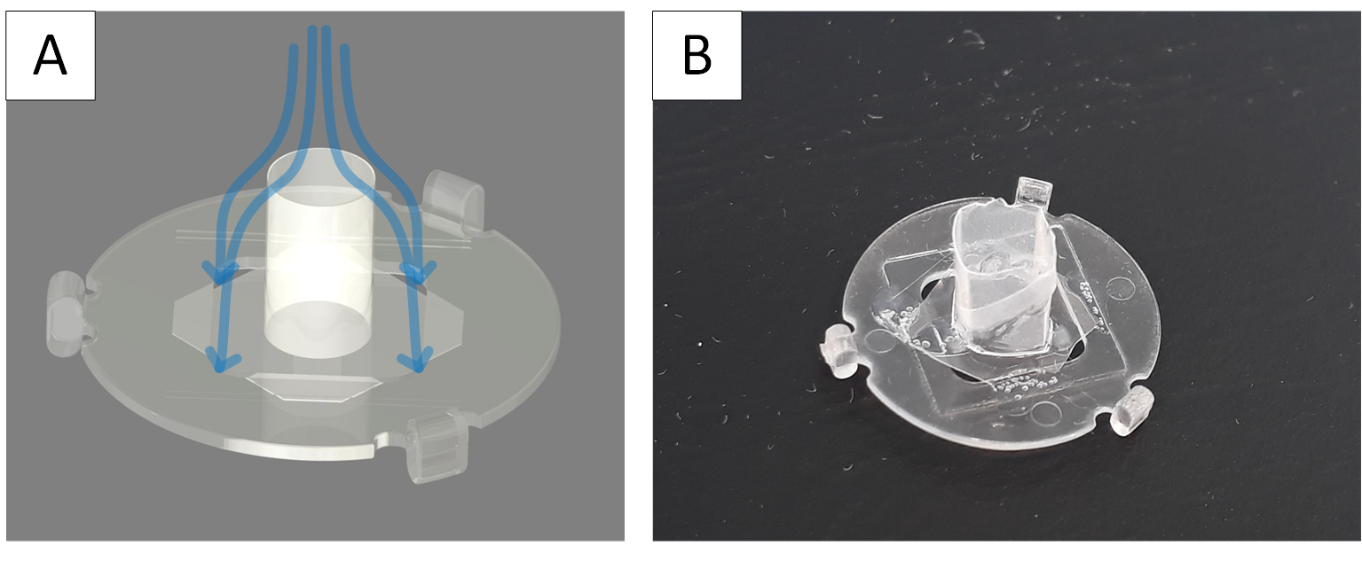
4.1. µ Inserts

The step from well-known and established 2D cell cultures to advanced 3D cell cultures is related to many innovations in culture management, working methods, and equipment. For many users, these challenges are associated with incalculable risks, which is one of the reasons why the application of 3D cell cultures in research and development has a high barrier to entry [113]. The so-called semi-active systems were developed in order to find a simple way for us to get into this field [114]. They combine the advantages of the well-known 2D cell culture with the essential possibilities offered by a 3D culture. These semi-active systems are based on units that can be used in the familiar 24-well microtiter plates. The laboratory handling of 24-well plates is part of common training and ensures comfortable manipulation by the user. Similar developments have been initiated in recent years by leading manufacturers of laboratory products [115]. In our case, within the inserts, different microstructured scaffolds can be used. This possibility is unique to our system. In this way, two fluidically separated compartments are formed in one well. If the microstructured scaffolds are porous, a certain flow through the scaffold and the cell culture contained in it to the other compartment can be achieved by a slight hydrostatic pressure generated by different levels of media in both compartments. This way, a very simple variant of an active perfusion of the cell culture is possible. Of course, the flow rate is not constant, as it would be with an active pump, but by recurrent pipetting of the liquid between the compartments, a volatile flow through the membrane can be generated. Due to the design of the systems, this recurring pipetting can be easily and quickly done by a robot. A good diffusive supply of the cell culture is also possible using an appropriate membrane. In addition, the use of high gradients of pharmaceutically active medium components and the partial segregation of cell products into the medium are possible. The handling is simple, and the systems can be easily inserted into the well and removed with tweezers. The inserts position themselves automatically, which even allows the use of multipettes or automatic transfer stations and pipetting robots. The lid of an MTP can be used conventionally, which prevents the evaporation of media and cross-contamination and allows convenient handling and transport. Due to the small distance between the scaffolds and the original well bottom, the cell culture can also be observed via inverted microscopy. Maximum compatibility with established laboratory methods is guaranteed. The systems can be manufactured cost-efficiently as disposables by injection molding. Thus, a simple and inexpensive entry into the capabilities of 3D cell culture is possible. As an example, the capability for air–liquid cultures is presented in the article. In addition to the ease of use of the systems, their application allows the characterization and observation of cell cultures in an intermediate-like stage between conventional 2D culture and sophisticated 3D cultures with active perfusion in microbioreactor systems. Thus, they provide a valuable source of data for linking both types of culture and, thereby, lead to a better understanding of the models. Figure 5 shows the schematic structure of a system and a picture of manufactured inserts.

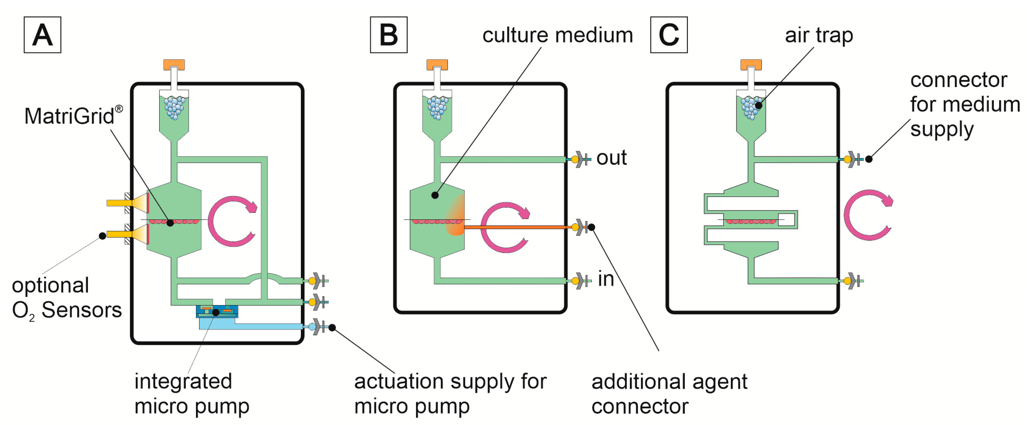
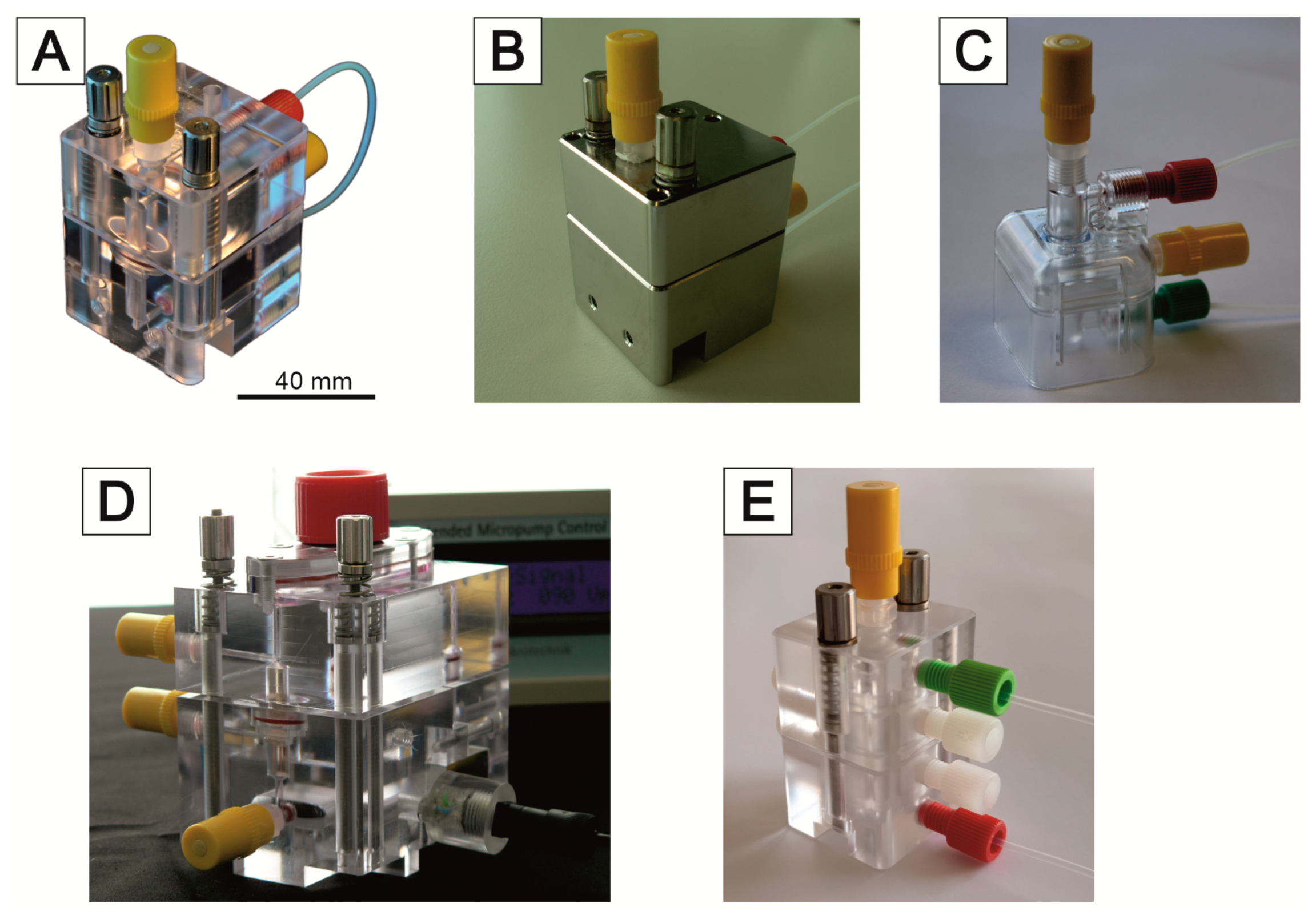
4.2. The Bioreactor Family

For the 3D culturing of cells, it is advantageous to replace a passive nutrient supply (diffusion) with an active one. Many different systems and concepts for 3D cell culturing have already been published. A concise overview can be found here [40,116]. A direct comparison of these systems is usually not possible because they are based on very different concepts and aims to be solved. However, there are systems/concepts that are very similar in functionality to ours, e.g., [117]. Our MatriGrid®s can be used for passive 3D culture as well as for active perfusion. For active perfusion of the MatriGrid®s, we have developed a number of micro bioreactors for various applications during the last 15 years. These systems have an internal volume of about 1.0 to 1.5 mL. The volume is adapted for the well size of a 24-well plate. The optimal flow rate depends on the cell type. There are two important factors that are mutually exclusive: on one hand, the O2 transport and, on the other hand, the shear stress on the cells. O2 transport is directly proportional to the flow rate. However, many cells do not tolerate large shear forces but have high O2 consumption. A compromise must be found here in order to optimally supply the cells but also not to overload them with shear forces (HepG2 25 µL/min, HepaRG 12 µL/min). In most cases, the cell culture medium is pumped in a closed loop. Different microbioreactor variants can be chosen for this purpose. In the simplest case, a peristaltic pump is used for perfusion. We have also integrated commercially available micropumps (Bartels MP6) or micropumps based on our own developments [118] for this purpose. Additionally, syringe pumps can also be utilized, and we used them to simulate time-dependent drug courses (MMT MDSP3f, MMT GmbH, Siegen, Germany). Figure 6 shows the fluidic scheme of the microbioreactors.
Like the MatriGrid®, the bioreactors are made of transparent polycarbonate (PC). This also allows a view into the system. To minimize absorption effects by the walls of fluidic channels, one type of reactor was also made of inert steel (1.4404). The first versions of the reactors were manufactured by milling. Because this is laborious and expensive, these systems are intended for multiple use. The material is suitable for sterilization by superheated steam and with ethanol. In order to provide a sufficient quantity of microbioreactors for laboratory work, we have developed a variant (Figure 7C) that is manufactured by injection molding and can be used inexpensively as a disposable product. PC was again used as the material because it performed well with the milled microbioreactors. This bioreactor consists of only two parts, which can be closed with an integrated snap closure. All microbioreactors are equipped with 1/4-28 thread connectors to allow easy and flexible connectivity (P-205, Upchurch Scientific Inc., Oak Harbor, Washington, DC, USA). The systems are vented via infusion plugs. Likewise, active ingredients can still be added via these plugs, or samples can be taken during operation (IN-Stopfen, PZN: 02133082, B.Braun, Melsungen, Germany).
Figure 7 shows a selection of variants manufactured and used. In most cases, we use the system pictured in Figure 8C. If we need information about the dissolved O2 concentration, the system of Figure 8A,D can be used. A sensor system can be integrated to measure dissolved oxygen concentration and consumption. This allows the real-time monitoring of the cells [119]. The reactor in Figure 7E has a very modular design. Inserts for perfusion or superfusion can be placed into the upper or lower part. This reactor is mostly suitable for experiments requiring superfusion. Due to this flexible design, it is also possible to realize lower or upper cross flows to the main flow. In this way, it is possible to generate gradients of active substances via the MatriGrid® (Figure 7B).
The analysis of the cells in such systems occurs mostly by the analysis of the supernatants or exchanged media using standard equipment. The other possibility is an on-demand analysis by integrated sensors, as described above, or the integration of sensors in the fluidic circuit, as described by Baca et al. in this issue or in the way of Zhang et al. [120]. More and more controlled parameters have recently been integrated into a self-standing system; this leads to complex and sophisticated systems, as shown by de Bournonville et al. [121]. From our point of view, it is more beneficial to introduce optical and biochemical read-out parameters, thus keeping the system compatible with standard laboratory read-out systems.
However, electroactive cells should be analyzed not only by optical-based assays but also by direct measurement of the electroactivity of such cells, respectively, in 3D cultures. Therefore, such devices have to be developed, which is the subject of the next section.

4.3. Analytical Unit/the 3D MEA

While extracellular recordings by microelectrode arrays (MEAs) are subject to the attenuation and temporal filtering of electrical signals, a relatively large number of excitable cells can be stimulated and recorded simultaneously. Due to the marker-free and non-invasive recording of the extracellular signals, long-term studies over days and months are possible [122].
The first application of an MEA chip for the detection of electrically active cells (cardiomyocytes) cultured in vitro was presented in 1972 by Thomas et al. [123]. The MEA used there consisted of gold-plated nickel electrodes that were applied to a glass substrate passivated with a structured photoresist. A glass ring was additionally applied to the substrate around the microelectrodes in order to create a defined culturing area. Since then, microelectrode arrays have been continuously developed. In the first extracellular derivation of dissociated neurons in 1980, Pine [124] used silicon dioxide instead of an organic photoresist to improve the insulation of the conductor paths. The problem of visualizing cells that had grown on the opaque metal microelectrodes could be solved by using transparent electrode arrays made of indium tin oxide (ITO) [125] or conductive organic polymers such as PEDOT:PSS [126]. Despite the worse signal-to-noise (S/N) ratio caused by using the ITO electrodes, Gross et al. used this MEA to stimulate a neural network [127]. In addition to these standard metal electrode MEAs, more complex structures based on open-gate field-effect transistors (FET) were also developed, in which individual neurons were cultured on the gates of the FETs. The first of these MEAs was developed by Fromherz et al. [128] and further developed for the stimulation of cultured neurons [129]. In basic research [130], pharmacology [131], and toxicology [132], commercial MEAs with planar electrode geometry for the use of monolayer cell cultures are widespread.
The proven advantage of 3D over 2D cell culture models is their similar behavior to in vivo behavior when mimicking signaling pathways or drug effects [133,134,135]. This leads to a great interest in the development of 3D MEA systems, addressing the increased complexity of 3D models. Planar MEA electrodes are insufficiently capable of acquiring signals from inside a 3D cell culture model. In order to overcome the limitations of planar 2D electrodes, a large number of different geometries (nanostructures) were tested during the development of 3D electrodes. All of these structures offer the advantage of an enlarged electrode surface and stronger adhesion of the cells to the electrode. Reduced distance between the nanostructured electrode and the cell resulted in improved signal quality [136].
For a spatial resolution of the electrical signals in 3D cell culture models that are several hundred micrometers to a few millimeters in size, needle electrodes with a length of up to several millimeters appear to be suitable. Several microelectrodes can be located on one or both sides on different levels of the electrode shank in order to achieve a spatial resolution of the 3D cell culture model [137]. When using needle electrodes, the 3D cell culture model (e.g., hydrogel) can be built up directly around the electrodes [138], or they can be inserted into the model (hydrogel or spheroid) after the cell culture has matured [139]. This type of 3D MEA also enables optical stimulation of the cells and the introduction of active substances directly into the interior of the 3D cell culture models via hollow needle electrodes [139].
The 3D cell culture models not only enable similar cell behavior to in vivo behavior but also require a more complex nutrient supply due to their size in order to avoid cell death in the center of the culture and to enable long-term cultures. Rowe et al., therefore, developed a scaffold made of a negative photoresist that, in addition, integrates electrodes on different levels of the scaffold, including microfluidic connections for optimal nutrient supply [140]. Another approach to perfused 3D MEA systems was developed by Musick et al., where electroactive cells are cultured on different levels of a cell culture chamber. The levels are micro-fluidically connected to each other and have integrated electrodes. It could be shown that electrical signals could be measured with a high degree of synchronicity between the electrodes of different levels [141].
If dissociated cells, cell aggregates (spheroids), or acute tissue sections are immobilized on planar microelectrodes, the cells adhere through the electrostatic or chemical interactions of the adhesion molecules of the cell membrane with the molecules of the surface coating of the MEA [142]. During cell depolarization and repolarization, the ion currents through the cell membrane cause an electric field in the cell’s proximity, which can be sensed by a microelectrode [143]. The ion current can be altered by influencing the ion channels with suitable inhibitors [144]. To maintain high S/N ratios and space resolutions, the electrode size should not be significantly bigger than the cell size. Because the amplitude extracellular electric field (caused by the action potential) decreases rapidly with the distance from the cell, the recording electrode should be placed within the range of several tens of micrometers. To prevent signal amplitude degradation, the electrode impedance should be as low as possible (electrode impedance is inversely proportional to its surface area), and the input impedance of the recording amplifier should be as high as possible.

Design and Construction of 3D MEA Sensors

The 3D MEAs developed by the Institute for Micro and Nano Technologies (IMN) MacroNano® at TU Ilmenau contain needle electrodes for spatial derivation in addition to bottom electrodes. The suitability of these 3D MEAs for measuring neuronal signals has already been proven [145,146].
The MEAs are equipped with a culturing chamber (Figure 8A), which can be perfused with the culture medium. Each 3D MEA has a three-level sensor surface made of gold electrodes to measure cell signals from stacked cell support foils (Figure 8B). The electrodes are arranged as 10 bottom electrodes and 3 needle electrodes, each with 3 electrodes at different heights. The sensing area is surrounded by an integrated reference electrode (Figure 8C).
The measurement setup, described by Bartsch et al. [145], is based on an integrated circuit from Intan Technologies (RHD2132); it enables the simultaneous sampling of all 57 MEA electrodes. Two RHD2132 chips are mounted on a circuit board equipped with spring-loaded contacts for the standard MEA format for 60 electrodes. The circuit board is mounted on an aluminum frame for mechanical robustness and electromagnetic shielding. The structure is controlled via the open-source software RHD2000 (Intan Technologies).
In addition to sensing, automation plays an important role when it comes to efficient drug testing and sampling in an autonomously driven bioreactor.

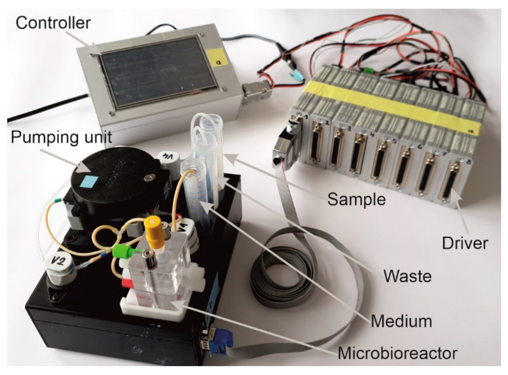
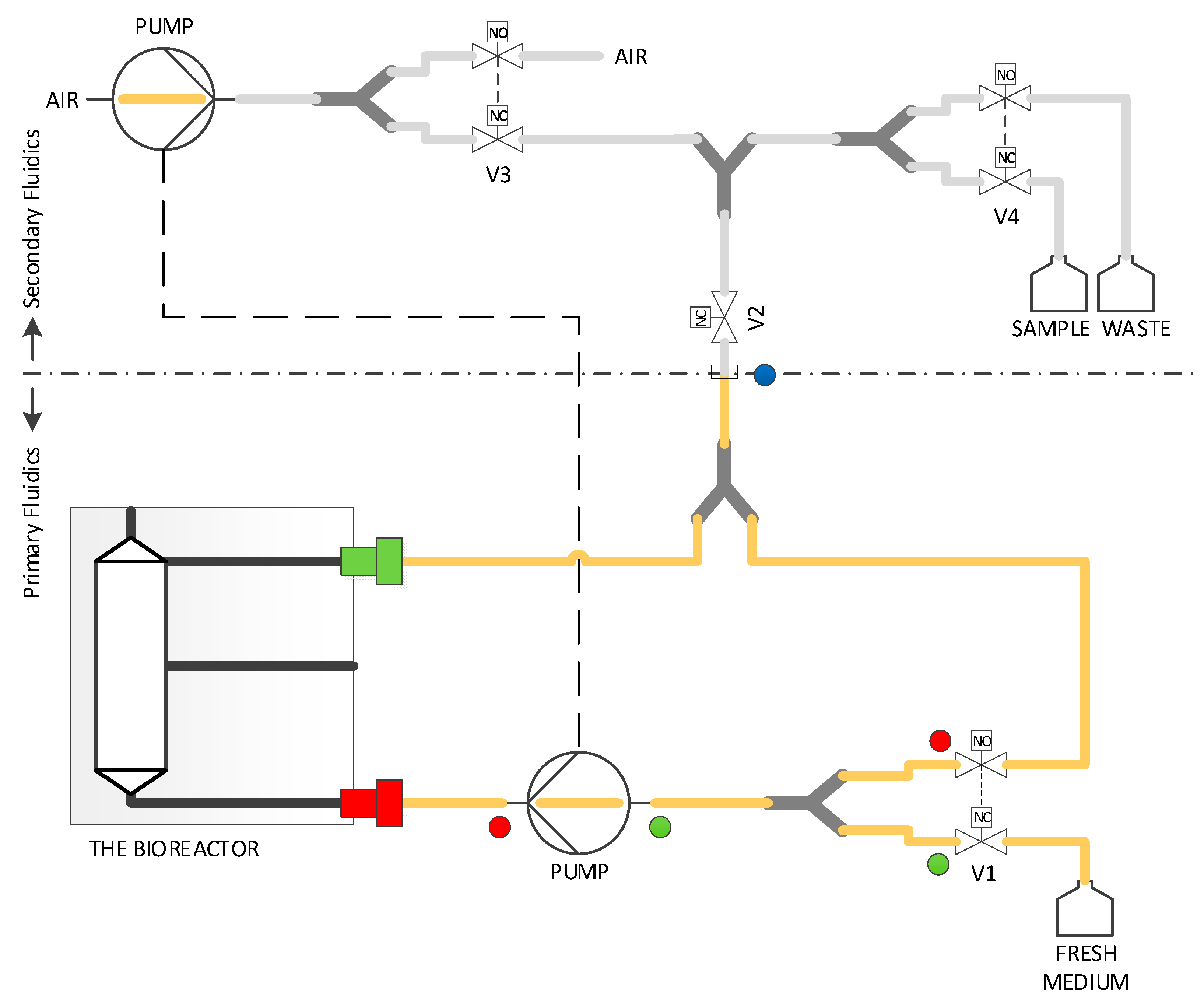
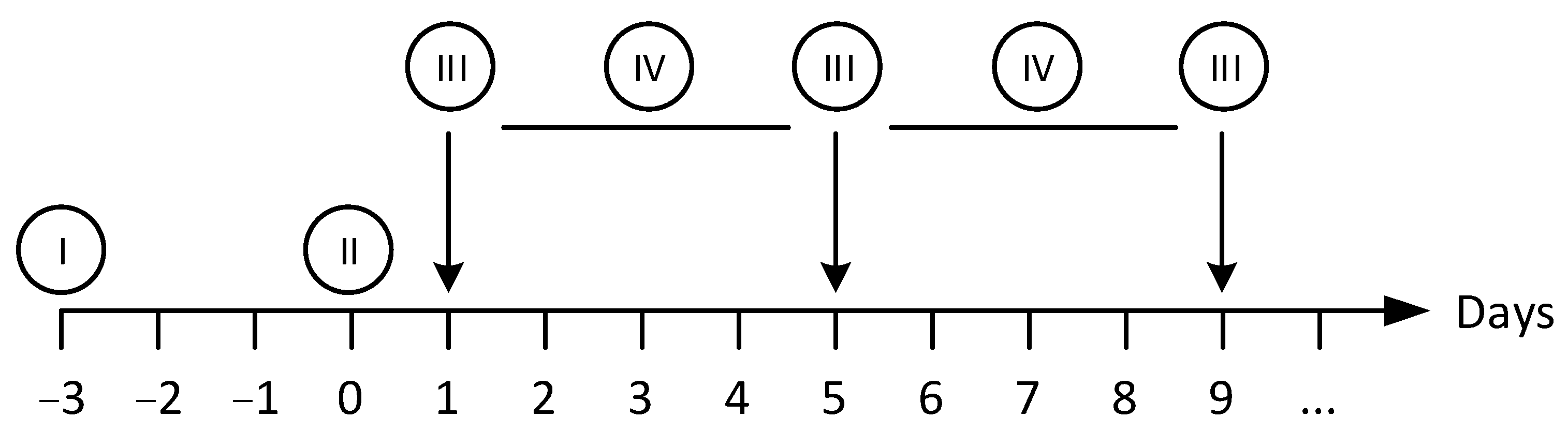
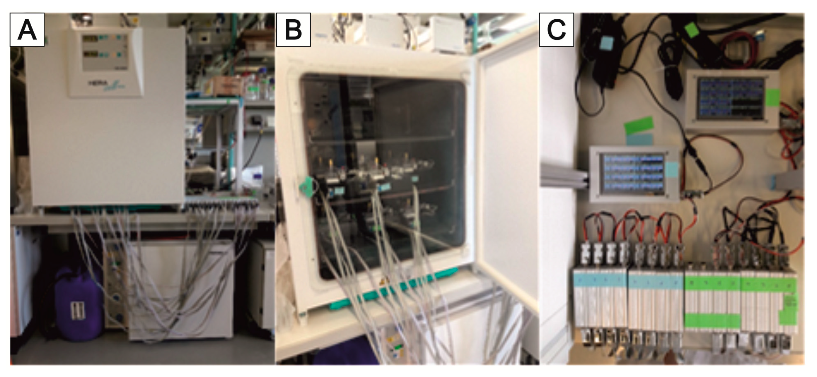
4.4. Automated Culturing and Drug Administration

The acceptance of organotypic 3D models ranges up to millifluidic scale systems [54,55], whereby most systems are based on static, passive fluidics [53,56,57]. However, dynamic (perfused) fluidic systems offer significant advantages, for example, increased transport of nutrients and metabolites within the 3D culture [58,59,60]. The fluid flow also has a direct influence on cell proliferation [61] by virtue of mechanical influences such as shear stress, pressure, and compression, which are essential factors for organ development and function [47]. Advanced cell culture techniques such as microfluidic organs-on-chips (OOCs) offer the opportunity to overcome these limitations. OOC is understood to mean microfluidic systems that are used to culture living cells in micrometer-sized chambers with a continuous flow and to model the physiological and pathological functions of tissues and organs [63]. Regardless of the manufacturing method and the material used, OOCs are suitable for studying biological phenomena that depend on tissue microarchitecture and perfusion [147]. Microfluidic OOCs, therefore, have the potential to become an alternative to animal models [148]. Individual organs-like models of lungs [149], skin [150], liver [151], kidneys [152], heart [153], and gut [154]) and various multi-organ systems [151,155,156] are available. OOCs have also been used for various clinical issues such as drug development and testing [157,158,159,160], cancer therapy [161,162], and oncoimmunology [163] or to identify antiviral therapeutics [164].
However, to date, no OOCs have been approved as an in-vitro alternative for animal testing in the relevant guidelines for chemical or pharmaceutical testing [165]. The reason behind this failure is the multiparameter conditioning that must replicate the actual biochemical, geometrical, and fluidic situation in the real organ. Moreover, in perfused long-term cell culture experimental systems, it is particularly important to have an automated medium exchange setup to maintain sterile and reproducible conditions [166]. Additionally, such an automated facility enables the real-time monitoring of cell health [167,168] or functional markers without disassembling the culture system. Since the structure of most body-on-a-chip systems is very complex, online monitoring is suitable for this purpose. Therefore, a number of new generation liver-on-a-chip systems were developed; they are equipped with biosensors or bio imaging to enable the online monitoring of pH and oxygen [169,170] and the cellular metabolic state [171,172] and the detection of cell-derived analytes in the culture medium [120,173,174]. This way, cells do not need to be removed from the perfused culture systems to identify drug toxicity and cellular health. In particular, quantitative analysis of cell-secreted proteins by microfluidic ELISA provides a suitable method for measuring non-invasively the drug toxicity in complex culture systems [120]. However, most studies use PDMS (polydimethylsiloxane)-based chip technologies that strongly interfere with the detection of soluble marker proteins due to adsorption.
We have developed a custom-made automated culturing and drug administration device for long-term measurements; it can also be used for the microbioreactors and scaffolds described in this account of research (Figure 9). In principle, the interface is adaptable to any other system with a similar fluidic scale. If the scaffolds are designed in the right way, organ-on-a-chip applications are possible. Because the automated media change is performed in defined periods, the collected medium can easily be fed into the usual laboratory analysis, such as readers, etc.; see the Section 6.
The perfusion and the automatic medium change are realized via two separate fluidic circuits within the pump and tubing system by switching different solenoid valves. Both circuits run via the same peristaltic pump (Figure 10). The medium in the bioreactor is continuously pumped through the MatriGrid® culture via the primary fluid circuit (perfusion). For this purpose, valve V2 is in the closed state (NC = normally closed), and the fluid circuit runs via the powerless open state (NO = normally open) of valve V1. For the medium change, the valves V1 and V2 are powered and switched on. The medium is now pumped into the secondary fluid circuit via the peristaltic pump and is directed there via the appropriate setting of valve V4 into the sample or waste container. The used medium is, thereby, replaced by the supply of the new medium. After the medium change, the sample in the tubing leading to the waste container is flushed and replaced by air.
An important endpoint in the toxicity assessment of chemicals and pharmaceuticals is repeated administration (repeated dose). The main objective of such an automated fluidic system is to characterize the toxicological profile of the test substance after repeated administration and to identify potential reversibility [175]. In order to replace animal experiments with in vitro methods, culturing systems that allow cells to be cultured in a controlled manner over a long period of time and administer defined repetitive application profiles are required. The presented culturing system with automatic medium change is, therefore, being examined for its suitability as a platform for repeated dose application for long-term experimentation, as discussed in the Section 6.
However, in the heart of every bioreactor are the various culturing scaffolds we call MatriGrid®s, which have been manufactured through the micro thermoforming technique described above.

5. The MatriGrid®-Family

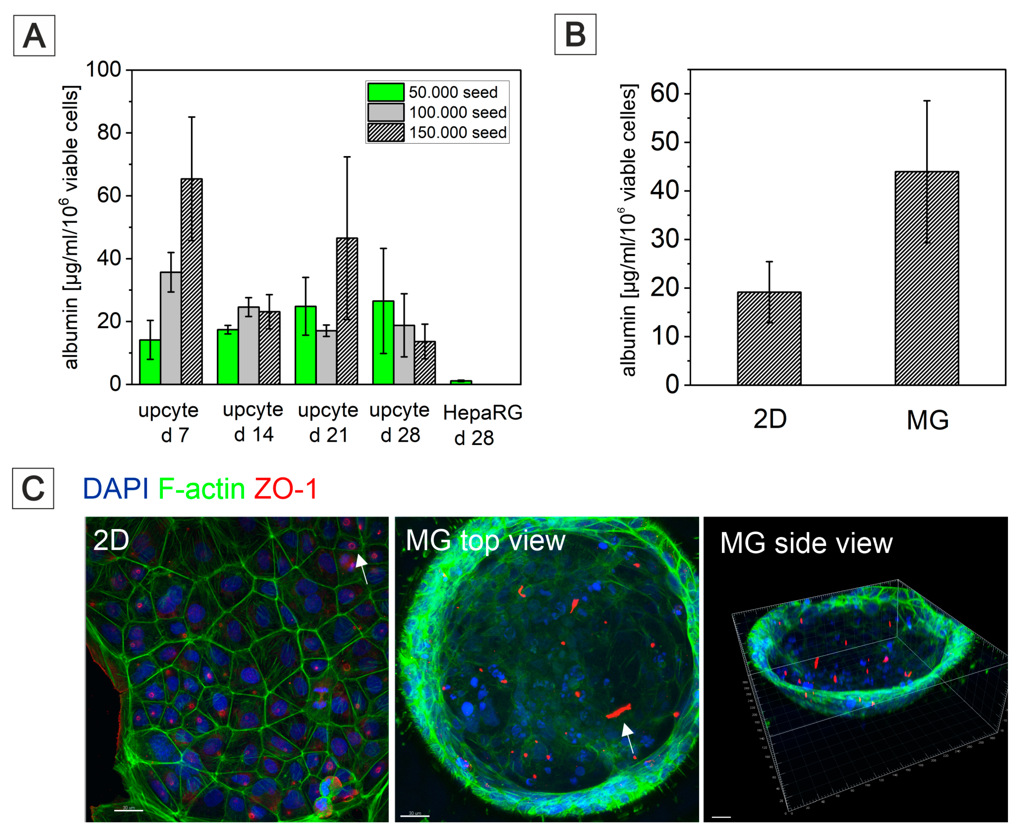
5.1. 3D Hepato MatriGrid®

Complimentary to various liver-on-a-chip models [176,177,178], MatriGrid®s with typical cavity/container-like morphology were used for culturing human primary Upcyte® hepatocytes and HepaRG hepatocarcinoma cells to mimic organotypic liver growth. Generally, biopsy-derived primary human hepatocytes (PHHs) are the gold standard for in vitro experiments on liver biology and for studying the hepatoxicity of a wide variety of drugs [179]. They can be cultured as monolayers only for a limited period of time due to rapid dedifferentiation and loss of the expression of CYP450 enzymes. Using Upcyte® technology that releases primary hepatocytes from cell cycle arrest by overexpressing the HPV oncogenes E6 and E7 without immortalization, long-proliferating hepatocytes from various donors with stable function were created recently [180]. Many studies have demonstrated that Upcyte® hepatocytes are suitable for preclinical drug metabolism and hepatotoxicity investigations [181,182,183]. Another hepatocarcinoma cell line, the HepaRG cell line, is also convincing due to long-lasting hepatofunctionality, but it has a significant disadvantage, namely, a long differentiation time of over 4 weeks with dimethylsulfoxide [184,185]. Both cell types were established in our MatriGrid® scaffolds and compared in terms of albumin production. Upcyte® hepatocytes were seeded with different starting cell numbers in MatriGrid®s, and albumin production was monitored over a time period of 28 days (Figure 11). The highest seed cell number resulted in a sharp increase in albumin secretion after 7 days of culturing in MatriGrid®s. Continuous culturing of the cells for up to 28 days resulted in an almost similar and stable albumin secretion that was independent of the seeding cell number. In contrast, differentiated HepaRG cells produced more than 20× less albumin than the Upcyte® hepatocytes grown for 28 days in MatriGrid®s.
Additional monitoring of cell numbers and viability revealed gradually increasing cell counts over time and stable viability up to 28 days for Upcyte® hepatocytes (data not shown). MatriGrid® versus monolayer (2D) culturing of Upcyte® hepatocytes for 7 days showed 2-fold increased albumin production due to the 3D environment in MatriGrid® cavities (Figure 11). This impressively demonstrates that the 3D environment provided by the cavity morphology leads to an improvement in the hepatofunctionality of Upcyte® hepatocytes. This result was further supported by labeling Bile canaliculi through ZO-1-F-actin staining in monolayer- and MatriGrid®-grown Upcyte® hepatocytes. Organotypic hepatocyte culture clearly promotes tubular versus ring-like Bile canaliculi labeled by zona occludens protein-1. With these data, we demonstrate that the organotypic 3D culturing of hepatocytes in MatriGrid®s significantly improves hepatofunctionality and, thus, is more suitable for studies on liver biology and hepatotoxicity than monolayer culture.

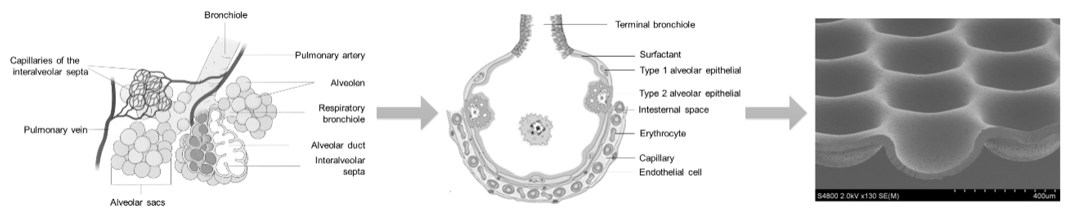
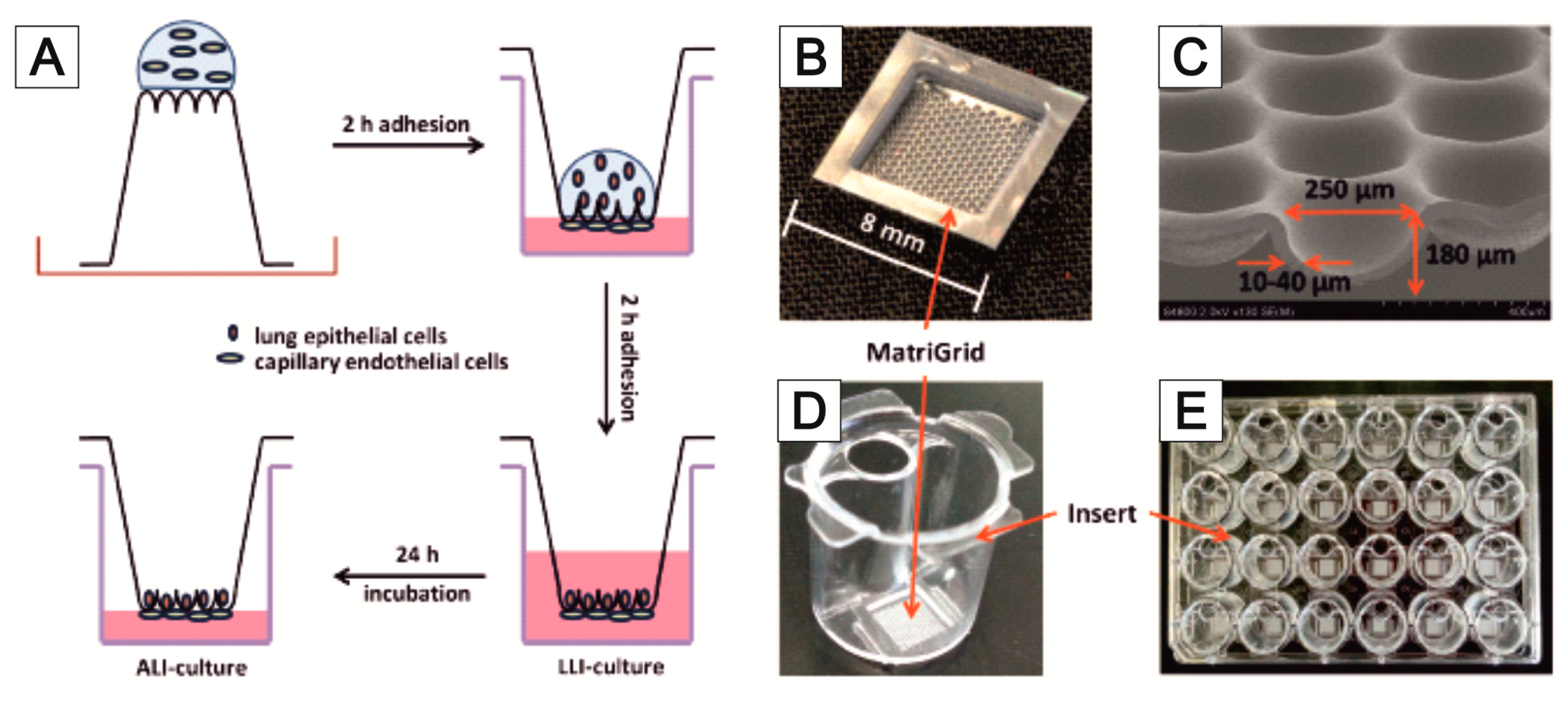
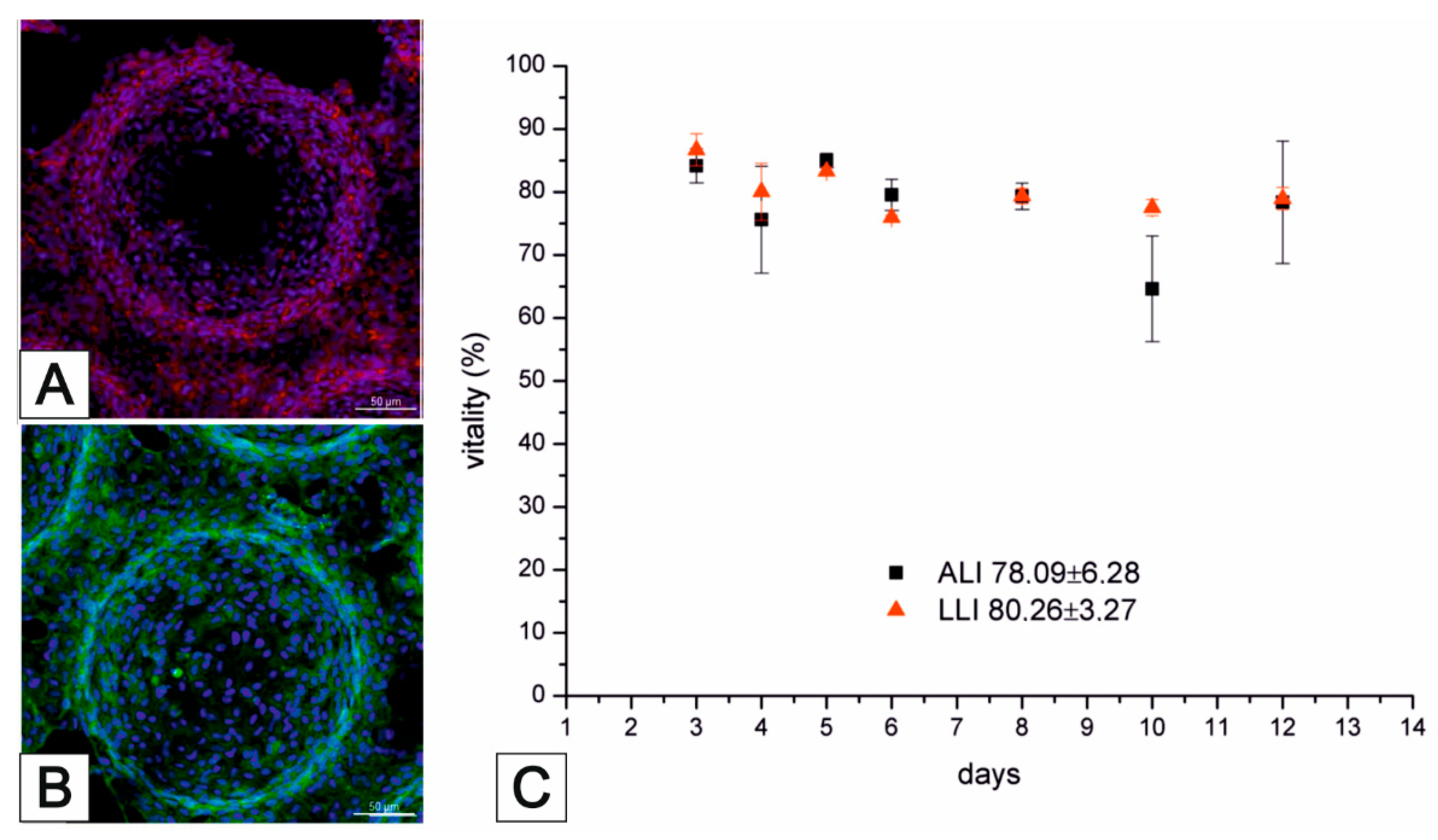
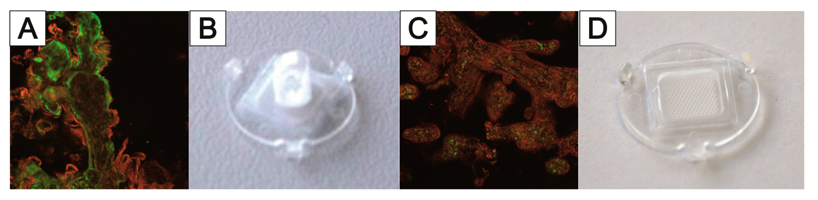
5.2. Lung MatriGrid®—An Example of Directed Oligocellular Coculture

Early cell culture models of the lung were mostly based on flat and porous membranes made of, e.g., polycarbonate (PC) or polyethylene terephthalate (PET), on which different combinations of alveolar cells, epithelial cells, and blood cells were cultured [186,187,188,189]. Khalid et al. have developed a lung-cancer-on-chip platform as a promising tool for the cytotoxicity evaluation of novel drug compounds [190].
While using well plate inserts in an air–liquid-interface could be applied to these models to mimic specific lung physiology, Huh et al. [149] were the first to report a lung-on-chip model with a uniaxially stretched membrane to mimic the breathing motion of the lung. In a similar approach, Huang et al. reported a hydrogel-based physiologically relevant model of human pulmonary alveoli [191]. That concept was later improved with a 3D-stained PDMS membrane [192] and the integration of impedance sensors to monitor cell behavior and membrane movement [193]. Furthermore, with respect to the alveoli dimensions, a biodegradable and stretchable biological membrane from collagen and elastin was reported to mimic the central aspects of the air–blood barrier [194]. Comparative to that approach within the MatriGrid®-family, a Lung-MatriGrid® based on the shape and size of human lung alveoli was developed using the previously described biotechnical microscale engineering and micro thermoforming technology (Figure 12).
The Lung-MatriGrid® permits the possibility of a 3D oligocellular coculture model of the blood–air barrier with respect to physiological characteristics. The blood–air barrier is characterized by an extremely thin and highly connected layer of epithelial cells that is spread over pulmonary capillaries [195]. Only a 1–2 µm thin structure supports the passive diffusion of respiratory gases [196]. To enable such organotypic exposure of the alveolar epithelia cells against ambient air, the oligocellular coculture model is cultured under an air–liquid interface (ALI) condition. This more physiological ALI culturing is realized by attaching the Lung-MatriGrid® onto the previously described semi-active system (Figure 5). The barrier itself is realized by the seeding of capillary endothelia cells to the basal side of the scaffold, while alveolar epithelia cells are brought into the alveolar-like cavities on the apical side (Figure 13)
The medium in ALI culturing is only present underneath the basal side of the scaffold supply of the apical cells, which is ensured by the porosity of the scaffold (pore diameter = 2–4 µm, pore density = 106 pores/cm2, thickness = 10–40 µm). Viability and metabolic activity of alveolar epithelial cells (A549) and capillary endothelia cells (EAhy.926) cultured in a lung MatriGrid® are shown to be not compromised in comparison to the culturing in a liquid–liquid interface (LLI) culture over 12 days (Figure 14). Additionally, A549 forms a thick monolayer, with the expression of cell-adhesion molecules (ZO-1, E-cadherin) in the cavities of the Lung-MatriGrid® (Figure 13A). Since the Lung-MatriGrid® can be reversibly separated from the insert system, the cell layer on the scaffold, as well as the cell culture medium, can be evaluated with established methods such as (immuno)-histochemical staining or ELISA to identify changes in cytokine levels or the expression of cell-adhesion molecules due to exposure to, e.g., nanoparticles. Further research is ongoing in the DFG project (DFG 397981139) in cooperation with the Institute of Environmental Toxicology at Martin-Luther-University Halle-Wittenberg to examine the toxicity of BaSO4 nanoparticles on primary cells and cell lines in Lung-MatriGrid®s.

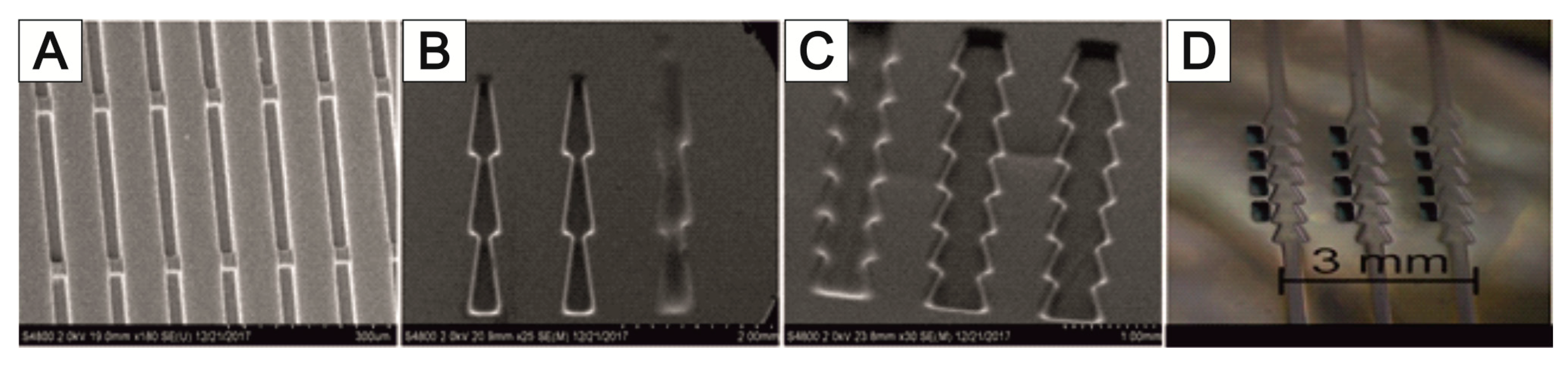
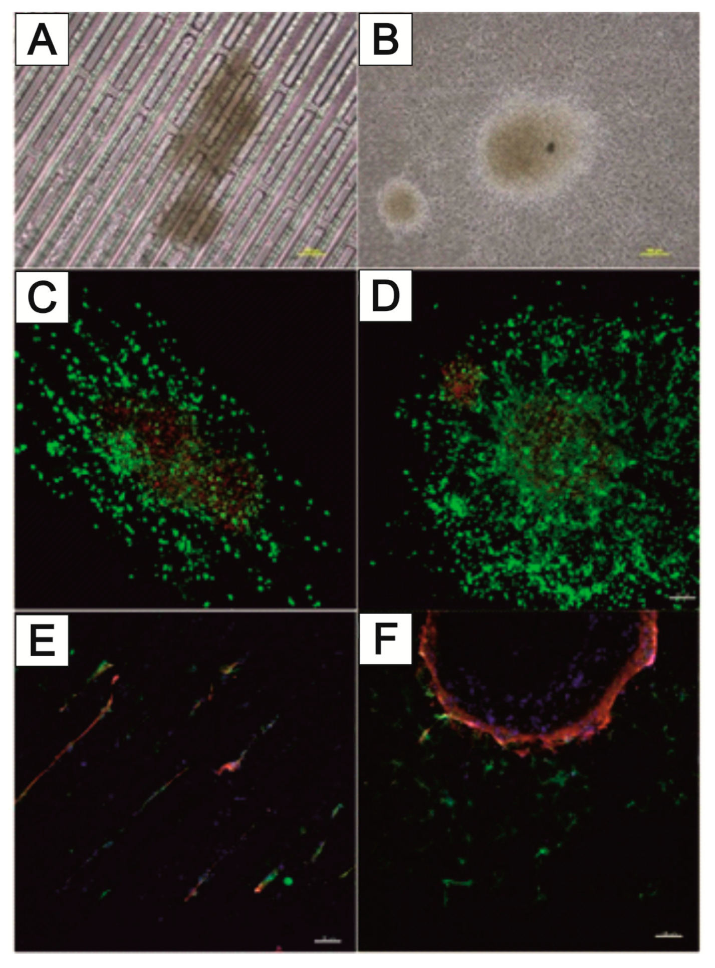
5.3. NeuroGrid®—Scaffolds for the Manipulation and Directed Growth of Neurons and Cerebral Organoids

It is well known that different cellular processes, such as attachment, proliferation, directional migration, and differentiation of neurons, are dependent on morphological and biochemical cues in the surrounding surface [197,198,199]. In this way, the direction and outgrowth of axons and dendrites have been studied by symmetric or asymmetric shapes of trenches [200,201] or specific microplates [202] to guide the connectivity between 3D neuronal cell clusters [203] or to record muscle activity after stimulation of axons in different microfluidic chambers [204]. In addition, there are indications found that the migration capacity of neural cells depends on the stage of neuronal differentiation [205]. Additionally, circular 3D PDMS scaffolds have been used for defining spheroid-like neuronal cell agglomerates [206]. Here, we describe the design of polymeric scaffolds in PC, which should be used as a proof-of-concept study for the handling and shaping of neurons and neuronal organoids.
For this reason, it is being investigated whether appropriate modifications of the MatriGrid® scaffold can enable the directed growth of neurons to reproduce desired morphologies, with the vision of developing flexible tools to mimic the complex hierarchies of neuronal tissue. Various designs of MatriGrid®s were used to induce the guided growth of embryonic and adult neurons. The set of MatriGrid®s with function-dependent embossed structures is given in Figure 15. Besides the fact that neurons are guided easily by microchannels, the geometries of our structures were inspired by the size of neuronal fiber bundles, which are in the range of approximately 500 µm in the case of a cortical column [207,208].
Primary rat cortical neurons were used to allow directed growth through the structures. In the same way, the culturing of neurospheres from induced pluripotent stem cells (iPSC) was investigated. MatriGrid® cultures are also used to bring the guided neurons into close contact with microelectrodes of 2D and 3D MEAs so that it is easier to capture the neuronal signals. That targeted application of MatriGrid® scaffolds can easily be extended by stacking those scaffolds to create complex 3D models to evaluate real 3D network signals from neuronal cells.
Figure 16 shows the directional growth of neuronal cells that have grown out of neurospheres. The typical radial outgrowth of neuronal cells from a neurosphere can be seen on the unstructured PC foil (Figure 16B), although it is not possible to evaluate the growth of neurons within the trench structure using bright field microscopy (Figure 16A). Cell staining is needed to estimate any guided neuronal cell growth inside the narrow NeuroGrid®-structures. Live–dead staining as well as immunofluorescence staining against neuronal markers microtubulin-associated protein 2 (MAP2) and βIII-tubulin (TUBB3) were performed. In addition, the cell nuclei were stained with DAPI (blue). The trench structure forces a directional growth compared to the unstructured PC foil (Figure 16C,D). Mainly viable (green-stained) cells outside the neurospheres can be seen. Viable cells, on the other hand, are present in the neurospheres. While TUBB3-stained neurons grow along the trenches, MAP2-stained cells do not undergo this directed growth and are also found in the areas between the trenches (Figure 16E). In contrast, on the unstructured PC foil, mainly MAP2-stained cells grow out of the aggregates of the rat cortex neurons, and only a small number of TUBB3-stained cells can be seen (Figure 16F).
A major problem in deriving neuronal signals is the growth of neuronal cells outside the sensor area of the MEA. This circumstance makes planning more difficult and prevents the standardization of the experiments. For this reason, the targeted application of neuronal cells to the electrodes of the 2D and 3D MEAs was tested using MatriGrid® foils (Figure 17A). Normal PC foils and MatriGrid® with a towering tree structure were used for the experiments with 2D MEAs. Special 3D MEA foils with cutouts for the 3D needle electrodes were used for targeted positioning on 3D MEAs. In both variants, neurospheres were pre-cultured on the foils for 7 days and then transferred to the 2D or 3D MEA and cultured further for at least 7 days. The signals were recorded daily after the transfer to the MEA. The neurospheres for the 2D MEA were pipetted as centrally as possible onto the foil or into the tree structures of the MatriGrid®. For the 3D MEA, neurospheres were placed in the structures on the ridges between the cutouts for the needle electrodes. All foils were coated with Geltrex in order to cover the entire foil with cells. Figure 17 shows the behavior of the neuronal cells after application over a culturing period of 9 days. While the neurospheres are intact on the first day after the transfer (Figure 17B), they show gaps during longer culturing, which become larger the longer the foils are cultured on the MEAs (Figure 17C,D). Individual outgrown neuronal cells can be seen within these gaps. However, it cannot be seen whether these have grown on the foil or the MEA (Figure 17D). After a few days, detached cells are present in the medium, both at the edge of the foils placed (Figure 17E) and over the remaining MEA surface (Figure 17F). These do not adhere to the surface of the MEA but form cell aggregates. It could also be observed that the PC film slips on the 2D MEA when changing the medium (Figure 17F).
Figure 18 shows the 3D MEA foil before it was transferred to the 3D MEA (Figure 18A). When the foil was applied, it was transferred to the 3D MEA with the cells facing down. When neurospheres are cultured in the tree structures of the 3D MEA foil, they can be placed directly on the needle electrodes (Figure 18B); when cultured on the ridges between the cutouts, it is also possible to position the neurospheres specifically on the bottom electrodes of the 3D MEA (Figure 18C). It should be noted that individual neurospheres can become detached from the 3D MEA film during transfer (comparison of Figure 18A,B).
Figure 19 shows an example of a 3D MEA measurement of neuronal signals after the targeted application of a 3D MEA foil. Neural signals were measured at the opposing electrodes B-014 and B-020 (comparison of Figure 19A,B). Here, electrode B-020 is a bottom electrode that is opposite the middle needle electrode B-014. The signals from the two electrodes show a high degree of synchronicity (Figure 19C). The background noise of the electrodes is between 5 and 10 µV; mainly negative spikes with a maximum of 20 µV were measured. Both signals contained bursts (see Materials and Methods in the Supplementary Information).
Besides the use for the directed growth of neurons and a targeted application to 2D or 3D MEAs, the MatriGrid®s can also be used as a handling tool to create more uniform spheroids of neuronal cells. For this purpose, dissociated rat cortex neurons were pipetted into the cavities of the MatriGrid®s. The cavities were previously coated with anti-adherence rinsing solutions. The spheroids precultured and shaped in the MatriGrid® were transferred directly onto 2D MEAs or into structures of other MatriGrid®s (Figure 20). For both approaches, the attachment of the spheroids and the outgrowth of neurons were verifiable. A big advantage of that approach in forming spheroids is the possibility of defining the diameter of the spheroid through the size of the cavities. Because of that, the spheroids are highly adaptable to the purpose they will be used for.

5.4. TissGrid®

The need for adapted scaffold structures is not only important in cell cultures based on cell lines or primary cell cultures; the culturing of explants or tissue slices can also benefit from the advantages of a scaffold approach. The scaffold creates an adapted microenvironment for the specific explant and, thus, optimal survival conditions. This is particularly important for longer culturing periods. Flow-induced shear stress has a big influence on cells and tissues [209,210,211,212,213], either in a positive way, mimicking the effects of vascularization, or in a negative way on sensitive cells and tissue slices, where the stress damages the cells. In a case study, we have examined this effect on placenta tissues, called placenta explants, because drug and particle transport across the human placenta is a deciding factor for fetus development [214,215]. It is generally known that fluidics also have a major influence on the cellular phenotypes of the placenta [216]. Therefore, it is desirable not only to culture the explants statically but also to culture them inside microfluidic systems. Placenta explants are sensitive tissue structures that lose their integrity under fluid shear stress; they cannot maintain their viability for an indefinite period. We examined the fluid stress effects on explants under different fluidic regimes. Following the observation that placenta explants are very sensitive, we designed a new scaffold structure that combined the potential shelter function of a porous cavity with the advantage of better fluidic supply with respect to nutritious flow. The TissGrid® structure is designed in the following way. A central cylindrical cavity standing on a porous base surface is used to accommodate the explant. This can be easily inserted into the scaffold from above without damage. The cavity is made of microporous transparent polycarbonate film by thermoforming. Microscopic observation of the explant is possible during culturing. Due to the porosity, a very good diffusive supply of cells is possible. In order to achieve an effective flow around the explant cylinder and, thus, high diffusion gradients, bypass openings were inserted at the corners of the base surface. The base surface was also made of porous polycarbonate film, which also allows the microscopic inspection of the samples. To integrate the system into the microreactors described above, the scaffolds were fixed onto a carrier chip. In order to avoid an undesired influence on cell culture, no adhesives should be used to bind the scaffolds. Especially in long-term cultures, substances may leach out of the adhesive. In the application described here, the scaffold parts were, therefore, bonded with solvent. This could be completely removed by appropriate heat treatment in a vacuum. This way, easy storage and handling and good sealing of the scaffold in the bioreactor are possible. A schematic representation of the TissGrid® is shown in Figure 21.
We were able to show that with the specially designed TissGrid®s, a flow-through protective structure could be set up, which enables the explants to be supplied with medium/serum flowing past while maintaining viability [217].
Under conventional culture conditions, without the influence of test substances, we were able to observe relatively stable glucose consumption and stable lactate production in placenta explants in a conventional microtiter plate (MTP) for up to 10 days, which indicates good placental functionality and metabolism. By changing the culture conditions with the help of specially developed fluidic systems (TissGrid®s in bioreactors [217]; Figure 22), a placental-active metabolism could even be stimulated, which shows an increased production of estradiol by the syncytiotrophoblast at flow rates of 100 µL/min of the culture medium (unpublished data). The substrate structures were thoroughly tested and led to the specially developed TissGrid®. In addition, different flow rates were varied in these experiments.
In contrast, the relative decrease in estradiol production under static (not perfused) conditions (2D, static plate) and the low flow rates of 10 µL/min indicate the degeneration and decreased function of the explants. Preliminary tests also showed that it was not possible to carry out tests at high flow rates in the structures developed for 3D cell culture (called MatriGrid®s (Figure 22)). The tissue lost its intact structure (Figure 22C). With the help of the TissGrid®s in special MTPs or microbioreactors designed for this purpose (Figure 22A), which are to be standardized, a further time window can be opened up due to the supply of the placenta explants with culture medium.
Besides the culturing of primary cells and even explants in fluidic setups, as described before, long-term experiments bear a high potential for the application of MatriGrid® scaffolds. In the following section, we describe a selected example where hepatocytes were cultured and characterized for up to 28 days.

6. Long-Term Automated Culturing and Drug Administration

For the examination of hepatocytes after repeated administration of a hepatotoxic substance, primary Upcyte® hepatocytes (uHep) were seeded in the MatriGrid®.
Upcyte® hepatocytes (uHep) are established as a model for the metabolism of metabolically stable compounds [218]. Primary donor cells are used for uHeps, which are stimulated to proliferate using the E6 and E7 genes of human papilloma virus 16 [180]. This has the advantage that the immortalization avoids a change in the phenotype of the primary liver cells. The activities of CYP1A2, CYP2C9, and CYP3A4, when stimulated by CYP inhibitors, are equivalent to or higher than their activities in primary human hepatocytes [219], but fluctuations in the expression of various genes between the individual donors can be observed [182,219,220].
The schematic test procedure is shown in Figure 23. For the test, 150,000 uHeps of donor 10-03 was used as the starting cell count and “pre-cultured” statically in the MatriGrid® in an MTP for 3 days (Figure 23I). The MatriGrid®s were then transferred to the bioreactors (Figure 23II), where they were cultured automatically. The MatriGrid® cultures were perfused at 12 µL/min, and the medium was changed daily. The first addition of the drug acetaminophen (APAP) took place after 24 h during the medium change and then again after 4 days of incubation (Figure 23III). The drug addition was repeated six times. Between drug additions, the cell cultures were incubated with daily medium changes (Figure 23IV). The exchanged medium was collected separately for each bioreactor. APAP concentrations of 0.25, 2, and 5 mM were investigated. For this purpose, the albumin and LDH concentrations were determined from the collected medium.
Figure 24 shows the laboratory setup for the experiment. Here, 14 parallel operating bioreactors (2× control, 4 × 0.25 mM, 4 × 2 mM, and 4 × 5 mM) were kept in the incubator throughout the experiment.
To investigate the suitability of the automatic perfusion system for repeated dose studies, the repeated addition of acetaminophen in concentrations of 0.25, 2, and 5 mM was tested. The long-term culturing of the primary Upcyte® hepatocytes (uHep) in the bioreactor with automatic medium change by the culturing system was carried out as mentioned above. Albumin secretion and LDH leakage by the Upcyte® cells, treated with repeated doses of APAP, were normalized against the initial values measured on the first day of culturing, which were set to 1.
Figure 25A shows the course of albumin secretion from the Upcyte® hepatocytes after repeated administration of 0.25, 2, and 5 mM APAP. Relative to albumin secretion on day 1, the addition of acetaminophen at the concentration of 0.25 mM resulted in a continuously increasing albumin secretion of the treated Upcyte® hepatocytes, peaking on day 20 with a 14.5-fold increase. Repeated addition of 2 mM APAP also resulted in an increase in albumin synthesis, with two peaks on day 14 (12-fold increase) and day 22 (16-fold increase). It was observed that each addition of APAP led to a short impairment of cellular albumin secretion, followed by a further enhancement in albumin synthesis to an even higher level. This effect was most notable at a concentration of 2 mM APAP. Repeated dosage of a high APAP concentration (5 mM) impaired albumin secretion by the Upcyte® hepatocytes from the beginning, and after the APAP pulse on day 5, the cells almost ceased albumin secretion.
Analysis of LDH secretion (Figure 25B) showed that after the first pulse of the highest concentration of APAP (5 mM), cell death occurred, visible as a 2.6-fold increase of LDH secretion on day 3 of perfusion culturing. A slight increase in LDH release was also observed after the first dose of 2 mM APAP on day 2. The lowest APAP concentration (0.25 mM) did not lead to significant LDH leakage, indicating that no cell damage occurred at this APAP concentration.
We were able to perfuse Upcyte® hepatocytes seeded in MatriGrid®s in an automated perfusion system for up to 24 days. Relevant biological endpoints (albumin, LDH) were used for the analysis of the cell health and functionality of the perfused Upcyte® hepatocytes. A repeated dose–response study, with APAP as the investigated drug, showed the reversible induction of albumin synthesis by APAP concentrations of 0.25 and 2 mM. An up-to-16-fold increase of albumin production by 2 mM APAP, compared to the albumin secretion at the first perfusion day, was detected. It is conceivable that under stress conditions (in the presence of the toxic APAP), the cells increase their metabolism to reduce toxicity. The increase in albumin synthesis could have a counter-regulatory function in binding the high drug concentrations in the blood. In contrast, a higher APAP concentration (5 mM) impairs the albumin production of Upcyte® cells directly after the first drug addition, with no apparent recovery over time. This indicates cellular damage leading to decreased cell functionality, as shown by reduced albumin secretion. In experiments with spheroids from HepG2/C3A cells [221], Fey et al. found a chronic impairment of viability of the cells to the repeated addition of 10 mg APAP per mg of protein. Lower concentrations showed no lethal effect, while higher concentrations led to an immediate loss of cell viability. In studies with a significantly higher APAP concentration (18.6 mM) on primary hepatocytes in 2D cultures in 96-well MTPs, a reversible decrease in albumin concentration after the addition of the used drug was also observed [222,223].

7. Conclusions and Outlook

We close the description of our account of research with a classification with respect to contextualization and a discussion of further perspectives of technological development.

7.1. Conclusions

We have shown that polymeric substrates for 3D culturing can be adapted to the needs of specific cells of different organs. Starting with the basic idea of forcing cells to develop 3D contacts with each other by simultaneously guaranteeing a sufficient supply of oxygen and nutrients [92,224], the first MatriGrid® was developed with defined porous and non-porous regions in its structure. We apply this basic structure to different liver cell types. Such cavities reflect even the real morphology of lung alveoli, which opens the way to an oligocellular model of the alveoli, with site-specific adhesion of the suitable cell types. Such MatriGrid®s can be integrated into insert systems that are used in MTPs or into our own specially developed micro bioreactors. Other morphologies, such as linear trenches, are suitable for neurons and can be used for the examination of the differentiation and evolution of neuronal cells. In addition, such cavities also allow us to form organoid-like structures. Furthermore, these NeuroGrid®s can be used for the transfer and manipulations of organoids for analytical purposes. A family of micro bioreactors that are optimized for our MatriGrid®s has been established, including a system for automatic long-term culturing and drug administration, allowing for experiments of even one month.
Specially adapted TissGrid® structures with an optimal fluidic design have also opened a way for culturing tissue slices, explants, and biopsy material in bioreactor devices. A short overview of the pros and cons of the presented systems is given in Table 2.

7.2. Contextualization and a Discussion of Further Perspectives of the Technological Development

We have chosen template transfer technology based on the principles of biotechnical multiscale engineering as the main strategy of designing scaffolds for advanced cell culture. Within this frame, microforming technologies are a versatile tool to construct cost-efficient microfluidic substrates, especially for cell culturing. Nevertheless, there are drawbacks that have to be considered. One issue is the design of real free-form 3D lumen-like structures, which might also be problematic for all traditional microsystem technologies. Using connection and packaging methods, such 3D lumen structures are realized, which is also possible for thermoformed foil designs. Within this scope is the clapping and stacking technology developed by our department [225]. Another way forward might be a family of 3D printing technologies, which is promising but still far from high-throughput production in this field.
Additionally, it would be fruitful to combine microforming with traditional micromachining technologies; one solution could be advanced lamination technologies such as thermo-blow mold lamination [226], which would allow for the integration of sensors and actuators in such micro devices in combination with polymer foil technology.
Within this context, especially for the examination of electroactive cells, it would be fruitful to integrate electrodes in polymeric fluidic and even cell culture substrates. One solution could be PEDOT-based polymeric systems [126]; however, these approaches lack the possibility of combining electronics in such a way that even porous substrates can be combined with fluidics.
Guided site-specific positioning and adhesion of specific cell types remain challenging, but it is a necessity for the future design of oligocellular organotypic devices. We have shown some building blocks on the way to this future, but there is still no general way to the complete realization of this promising scenario. Furthermore, the combination of the methods described above should allow the design of hybrid systems that mimic liver lobules or the cortical column. Nevertheless, the interplay between shape and morphological development, mechanical and physical cues, and cell differentiation gives a strong hint for the further development of scaffold-based cell culturing devices for the reproducible culturing of organoids, which should help pharmaceutical drug testing and the avoidance of animal testing especially.
Routine applications of automated systems for drug administration have demonstrated robust behavior, but the simultaneous use of more than 16 reactors, together with their driver units, in one regularly sized incubator is challenging. For this purpose, the parallelization and miniaturization of micro bioreactors would be advantageous. Other groups [68,227,228,229] have also recognized the need for parallelization and miniaturization, which will gradually become more and more important. For this reason, we are developing a parallel micro bioreactor platform based on a 24-well plate. Each well receives a micro pump so that active perfusion of the MatriGrid®s can take place independently in each well. The basis of the system is a 24-well from Greiner, into which the MatriGrid®s are inserted; the pump plate is then placed. In addition, this system is open on an ordinary 24-well plate so that the medium can be removed or added at any time with a pipette.

Supplementary Materials

The following supporting information can be downloaded at: https://www.mdpi.com/article/10.3390/bioengineering9050220/s1, Selected information regarding the micro bioreactor, MatriGrid® production, cell culture, staining methods, and MEA measurements can be found in the Supplementary Information material and methods [119,230,231,232,233,234,235].

Author Contributions

Conceptualization, A.S. (Andreas Schober), P.M., M.B., J.H. and S.S.; project administration and funding acquisition A.S. (Andreas Schober) and U.R.M.; methodology, D.B., P.M., M.B., J.H., F.W., M.K., J.M.K. and M.G., investigation D.B., M.B., P.M., J.H., F.W., S.S., I.S.S., F.G., D.E., B.S. and A.S. (André Schmidt); writing—original draft preparation P.M., M.B., J.H., F.W., S.S., D.B., J.B. and A.S. (Andreas Schober). All authors have read and agreed to the published version of the manuscript.

Funding

This research was funded by the Federal Ministry of Education and Research (FKZ-16SV3701, FKZ-03Z1M511/512, FKZ-03ZIK465, FKZ VIP+03VP00591, VIP+ 03VP08691, VIP+ 03VP08691), the Thuringian Ministry of Education, Science, and Culture (FKZ-B714-09064), AIF (FKZ-KF2731202AK0, FKZ-4457302CR8, FKZ- KK5240403NK1, FKZ: KK5240403NK1), the Carl-Zeiss Foundation (FKZ0563-2.8/399/1), and the 3D Neuro Project in the European Union′s FP7, Future and Emerging Technologies grant agreement No. 296590.

Institutional Review Board Statement

The study was approved by the respective local ethic committees (Jena University Hospital, registration number 1509-03/05).

Informed Consent Statement

Informed consent was obtained from all subjects involved in the study.

Data Availability Statement

No additional data, accept for the Supplementary Material is provided.

Acknowledgments

We thank Gregor Schlingloff, Heike Bartsch, Annette Hartung, and Karin Friedel for their excellent cooperation. In addition, we would like to thank our colleagues James Beck and his team at the Klinik für Kinder und Jugendmedizin Universitätsklinikum Jena, Olaf Witt and Ina Oehme at the German Cancer Research Center (DKFZ) in Heidelberg, the GSI Helmholtzzentrum für Schwerionenforschung in Darmstadt and Heidi Foth from the Institut für Umwelttoxikologie at the Martin-Luther-Universität Halle-Wittenberg, and Christiane Thielemann from the FH Aschaffenburg for using the evaluation software “DrCell”. We acknowledge support for the publication costs from the Open Access Publication Fund of the Technische Universität Ilmenau. Additionally, the Institute for Micro and Nano Technology (IMN MacroNano®) of TU Ilmenau has gratefully provided competent technical support.

Conflicts of Interest

The authors declare no conflict of interest. MatriGrid® is a trademark of the Technical University of Ilmenau.

References

  1. Jensen, C.; Teng, Y. Is It Time to Start Transitioning From 2D to 3D Cell Culture? Front. Mol. Biosci. 2020, 7, 33. [Google Scholar] [CrossRef] [PubMed] [Green Version]
  2. Habanjar, O.; Diab-Assaf, M.; Caldefie-Chezet, F.; Delort, L. 3D Cell Culture Systems: Tumor Application, Advantages, and Disadvantages. Int. J. Mol. Sci. 2021, 22, 12200. [Google Scholar] [CrossRef] [PubMed]
  3. Law, A.M.K.; de la Fuente, L.R.; Grundy, T.J.; Fang, G.; Valdes-Mora, F.; Gallego-Ortega, D. Advancements in 3D Cell Culture Systems for Personalizing Anti-Cancer Therapies. Front. Oncol. 2021, 11, 782766. [Google Scholar] [CrossRef]
  4. Langhans, S.A. Three-Dimensional in Vitro Cell Culture Models in Drug Discovery and Drug Repositioning. Front. Pharmacol. 2018, 9, 6. [Google Scholar] [CrossRef] [PubMed]
  5. Vunjak-Novakovic, G.; Scadden, D.T. Biomimetic platforms for human stem cell research. Cell Stem Cell 2011, 8, 252–261. [Google Scholar] [CrossRef] [PubMed] [Green Version]
  6. Yilmaz, B.; Al Rashid, A.; Mou, Y.A.; Evis, Z.; Koç, M. Bioprinting: A review of processes, materials and applications. Bioprinting 2021, 23, e00148. [Google Scholar] [CrossRef]
  7. Cagnin, S.; Cimetta, E.; Guiducci, C.; Martini, P.; Lanfranchi, G. Overview of micro- and nano-technology tools for stem cell applications: Micropatterned and microelectronic devices. Sensors 2012, 12, 15947–15982. [Google Scholar] [CrossRef] [Green Version]
  8. Farhat, W.; Hasan, A.; Lucia, L.; Becquart, F.; Ayoub, A.; Kobeissy, F. Hydrogels for Advanced Stem Cell Therapies: A Biomimetic Materials Approach for Enhancing Natural Tissue Function. IEEE Rev. Biomed. Eng. 2019, 12, 333–351. [Google Scholar] [CrossRef]
  9. Zhang, J.; Wei, X.; Zeng, R.; Xu, F.; Li, X. Stem cell culture and differentiation in microfluidic devices toward organ-on-a-chip. Future Sci. OA 2017, 3, FSO187. [Google Scholar] [CrossRef] [Green Version]
  10. Trettner, S.; Seeliger, A.; zur Nieden, N.I. Embryoid body formation: Recent advances in automated bioreactor technology. Methods Mol. Biol. 2011, 690, 135–149. [Google Scholar] [CrossRef]
  11. Xiang, Y.; Miller, K.; Guan, J.; Kiratitanaporn, W.; Tang, M.; Chen, S. 3D bioprinting of complex tissues in vitro: State-of-the-art and future perspectives. Arch. Toxicol. 2022, 96, 691–710. [Google Scholar] [CrossRef] [PubMed]
  12. Cheng, K.; Lai, Y.Z.; Kisaalita, W.S. Three-dimensional polymer scaffolds for high throughput cell-based assay systems. Biomaterials 2008, 29, 2802–2812. [Google Scholar] [CrossRef] [PubMed]
  13. Ong, S.M.; Zhang, C.; Toh, Y.C.; Kim, S.H.; Foo, H.L.; Tan, C.H.; van Noort, D.; Park, S.; Yu, H. A gel-free 3D microfluidic cell culture system. Biomaterials 2008, 29, 3237–3244. [Google Scholar] [CrossRef]
  14. Chen, C.; Townsend, A.D.; Hayter, E.A.; Birk, H.M.; Sell, S.A.; Martin, R.S. Insert-based microfluidics for 3D cell culture with analysis. Anal. Bioanal. Chem. 2018, 410, 3025–3035. [Google Scholar] [CrossRef] [PubMed]
  15. Eghbali, H.; Nava, M.M.; Mohebbi-Kalhori, D.; Raimondi, M.T. Hollow fiber bioreactor technology for tissue engineering applications. Int. J. Artif. Organs 2016, 39, 1–15. [Google Scholar] [CrossRef] [PubMed] [Green Version]
  16. van Duinen, V.; Trietsch, S.J.; Joore, J.; Vulto, P.; Hankemeier, T. Microfluidic 3D cell culture: From tools to tissue models. Curr. Opin. Biotechnol. 2015, 35, 118–126. [Google Scholar] [CrossRef] [Green Version]
  17. Hsiao, A.Y.; Torisawa, Y.S.; Tung, Y.C.; Sud, S.; Taichman, R.S.; Pienta, K.J.; Takayama, S. Microfluidic system for formation of PC-3 prostate cancer co-culture spheroids. Biomaterials 2009, 30, 3020–3027. [Google Scholar] [CrossRef] [Green Version]
  18. Schutte, J.; Hagmeyer, B.; Holzner, F.; Kubon, M.; Werner, S.; Freudigmann, C.; Benz, K.; Bottger, J.; Gebhardt, R.; Becker, H.; et al. “Artificial micro organs”—A microfluidic device for dielectrophoretic assembly of liver sinusoids. Biomed. Microdevices 2011, 13, 493–501. [Google Scholar] [CrossRef]
  19. Choi, J.; Kim, S.; Jung, J.; Lim, Y.; Kang, K.; Park, S.; Kang, S. Wnt5a-mediating neurogenesis of human adipose tissue-derived stem cells in a 3D microfluidic cell culture system. Biomaterials 2011, 32, 7013–7022. [Google Scholar] [CrossRef]
  20. Zeussel, L.; Hampl, J.; Weise, F.; Singh, S.; Schober, A. Bio-inspired 3D micro structuring of a liver lobule via direct laser writing: A comparative study with SU-8 and SUEX. J. Laser Appl. 2022, 34, 012007. [Google Scholar] [CrossRef]
  21. Marino, A.; Tricinci, O.; Battaglini, M.; Filippeschi, C.; Mattoli, V.; Sinibaldi, E.; Ciofani, G. A 3D Real-Scale, Biomimetic, and Biohybrid Model of the Blood-Brain Barrier Fabricated through Two-Photon Lithography. Small 2018, 14, 1702959. [Google Scholar] [CrossRef] [PubMed]
  22. Gottwald, E.; Giselbrecht, S.; Augspurger, C.; Lahni, B.; Dambrowsky, N.; Truckenmuller, R.; Piotter, V.; Gietzelt, T.; Wendt, O.; Pfleging, W.; et al. A chip-based platform for the in vitro generation of tissues in three-dimensional organization. Lab Chip 2007, 7, 777–785. [Google Scholar] [CrossRef] [PubMed]
  23. GravityPLUS(TM) 3D Culture and Assay Platform. 2015. Available online: https://www.selectscience.net/ (accessed on 5 May 2022).
  24. Tung, Y.C.; Hsiao, A.Y.; Allen, S.G.; Torisawa, Y.S.; Ho, M.; Takayama, S. High-throughput 3D spheroid culture and drug testing using a 384 hanging drop array. Analyst 2011, 136, 473–478. [Google Scholar] [CrossRef] [PubMed]
  25. Ganguli, A.; Mostafa, A.; Saavedra, C.; Kim, Y.; Le, P.; Faramarzi, V.; Feathers, R.W.; Berger, J.; Ramos-Cruz, K.P.; Adeniba, O.; et al. Three-dimensional microscale hanging drop arrays with geometric control for drug screening and live tissue imaging. Sci. Adv. 2021, 7, eabc1323. [Google Scholar] [CrossRef]
  26. Cho, C.Y.; Chiang, T.H.; Hsieh, L.H.; Yang, W.Y.; Hsu, H.H.; Yeh, C.K.; Huang, C.C.; Huang, J.H. Development of a Novel Hanging Drop Platform for Engineering Controllable 3D Microenvironments. Front. Cell Dev. Biol. 2020, 8, 327. [Google Scholar] [CrossRef]
  27. Huang, S.W.; Tzeng, S.C.; Chen, J.K.; Sun, J.S.; Lin, F.H. A Dynamic Hanging-Drop System for Mesenchymal Stem Cell Culture. Int. J. Mol. Sci. 2020, 21, 4298. [Google Scholar] [CrossRef]
  28. Raghavan, S.; Mehta, P.; Horst, E.N.; Ward, M.R.; Rowley, K.R.; Mehta, G. Comparative analysis of tumor spheroid generation techniques for differential in vitro drug toxicity. Oncotarget 2016, 7, 16948–16961. [Google Scholar] [CrossRef]
  29. Möller, J.; Pörtner, R. Digital Twins for Tissue Culture Techniques—Concepts, Expectations, and State of the Art. Processes 2021, 9, 447. [Google Scholar] [CrossRef]
  30. Ivascu, A.; Kubbies, M. Rapid generation of single-tumor spheroids for high-throughput cell function and toxicity analysis. J. Biomol. Screen. 2006, 11, 922–932. [Google Scholar] [CrossRef] [Green Version]
  31. Friedrich, J.; Seidel, C.; Ebner, R.; Kunz-Schughart, L.A. Spheroid-based drug screen: Considerations and practical approach. Nat. Protoc. 2009, 4, 309–324. [Google Scholar] [CrossRef]
  32. Tseng, H.; Gage, J.A.; Raphael, R.M.; Moore, R.H.; Killian, T.C.; Grande-Allen, K.J.; Souza, G.R. Assembly of a three-dimensional multitype bronchiole coculture model using magnetic levitation. Tissue Eng. Part C Methods 2013, 19, 665–675. [Google Scholar] [CrossRef] [PubMed] [Green Version]
  33. Souza, G.R.; Molina, J.R.; Raphael, R.M.; Ozawa, M.G.; Stark, D.J.; Levin, C.S.; Bronk, L.F.; Ananta, J.S.; Mandelin, J.; Georgescu, M.M.; et al. Three-dimensional tissue culture based on magnetic cell levitation. Nat. Nanotechnol. 2010, 5, 291–296. [Google Scholar] [CrossRef] [PubMed] [Green Version]
  34. Lewis, N.S.; Lewis, E.E.; Mullin, M.; Wheadon, H.; Dalby, M.J.; Berry, C.C. Magnetically levitated mesenchymal stem cell spheroids cultured with a collagen gel maintain phenotype and quiescence. J. Tissue Eng. 2017, 8, 2041731417704428. [Google Scholar] [CrossRef] [PubMed] [Green Version]
  35. Lewis, E.E.; Wheadon, H.; Lewis, N.; Yang, J.; Mullin, M.; Hursthouse, A.; Stirling, D.; Dalby, M.J.; Berry, C.C. A Quiescent, Regeneration-Responsive Tissue Engineered Mesenchymal Stem Cell Bone Marrow Niche Model via Magnetic Levitation. ACS Nano 2016, 10, 8346–8354. [Google Scholar] [CrossRef] [PubMed] [Green Version]
  36. Haisler, W.L.; Timm, D.M.; Gage, J.A.; Tseng, H.; Killian, T.C.; Souza, G.R. Three-dimensional cell culturing by magnetic levitation. Nat. Protoc. 2013, 8, 1940–1949. [Google Scholar] [CrossRef]
  37. Schober, A.; Fernekorn, U.; Singh, S.; Schlingloff, G.; Gebinoga, M.; Hampl, J.; Williamson, A. Mimicking the biological world: Methods for the 3D structuring of artificial cellular environments. Eng. Life Sci. 2013, 13, 352–367. [Google Scholar] [CrossRef]
  38. Tehranirokh, M.; Kouzani, A.Z.; Francis, P.S.; Kanwar, J.R. Microfluidic devices for cell cultivation and proliferation. Biomicrofluidics 2013, 7, 51502. [Google Scholar] [CrossRef] [Green Version]
  39. Park, J.; Li, Y.; Berthiaume, F.; Toner, M.; Yarmush, M.L.; Tilles, A.W. Radial flow hepatocyte bioreactor using stacked microfabricated grooved substrates. Biotechnol. Bioeng. 2008, 99, 455–467. [Google Scholar] [CrossRef]
  40. Coluccio, M.L.; Perozziello, G.; Malara, N.; Parrotta, E.; Zhang, P.; Gentile, F.; Limongi, T.; Raj, P.M.; Cuda, G.; Candeloro, P.; et al. Microfluidic platforms for cell cultures and investigations. Microelectron. Eng. 2019, 208, 14–28. [Google Scholar] [CrossRef]
  41. Meddens, M.B.M.; Liu, S.; Finnegan, P.S.; Edwards, T.L.; James, C.D.; Lidke, K.A. Single objective light-sheet microscopy for high-speed whole-cell 3D super-resolution. Biomed. Opt. Express 2016, 7, 2219–2236. [Google Scholar] [CrossRef] [Green Version]
  42. Chen, Y.; Zhang, L.; Chen, G. Fabrication, modification, and application of poly (methyl methacrylate) microfluidic chips. Electrophoresis 2008, 29, 1801–1814. [Google Scholar] [CrossRef] [PubMed]
  43. Chan, C.Y.; Goral, V.N.; DeRosa, M.E.; Huang, T.J.; Yuen, P.K. A polystyrene-based microfluidic device with three-dimensional interconnected microporous walls for perfusion cell culture. Biomicrofluidics 2014, 8, 046505. [Google Scholar] [CrossRef] [PubMed] [Green Version]
  44. Becker, H.; Schulz, I.; Mosig, A.; Jahn, T.; Gärtner, C. Microfluidic devices for cell culture and handling in organ-on-a-chip applications. Proc. SPIE-Int. Soc. Opt. Eng. 2014, 8976, 103–108. [Google Scholar] [CrossRef]
  45. Jena, R.K.; Yue, C.Y. Cyclic olefin copolymer based microfluidic devices for biochip applications: Ultraviolet surface grafting using 2-methacryloyloxyethyl phosphorylcholine. Biomicrofluidics 2012, 6, 12822–1282212. [Google Scholar] [CrossRef] [PubMed] [Green Version]
  46. Gencturk, E.; Mutlu, S.; Ulgen, K.O. Advances in microfluidic devices made from thermoplastics used in cell biology and analyses. Biomicrofluidics 2017, 11, 051502. [Google Scholar] [CrossRef]
  47. Bhatia, S.N.; Ingber, D.E. Microfluidic organs-on-chips. Nat. Biotechnol. 2014, 32, 760–772. [Google Scholar] [CrossRef]
  48. Gjorevski, N.; Nikolaev, M.; Brown, T.E.; Mitrofanova, O.; Brandenberg, N.; DelRio, F.W.; Yavitt, F.M.; Liberali, P.; Anseth, K.S.; Lutolf, M.P. Tissue geometry drives deterministic organoid patterning. Science 2022, 375, eaaw9021. [Google Scholar] [CrossRef]
  49. Borowiec, J.; Hampl, J.; Singh, S.; Haefner, S.; Friedel, K.; Mai, P.; Brauer, D.; Ruther, F.; Liverani, L.; Boccaccini, A.; et al. 3D Microcontact Printing for Combined Chemical and Topographical Patterning on Porous Cell Culture Membrane. ACS Appl. Mater. Interfaces 2018, 10, 22857–22865. [Google Scholar] [CrossRef]
  50. Marx-Blümel, L.; Marx, C.; Weise, F.; Frey, J.; Perner, B.; Schlingloff, G.; Lindig, N.; Hampl, J.; Sonnemann, J.; Brauer, D.; et al. Biomimetic reconstruction of the hematopoietic stem cell niche for in vitro amplification of human hematopoietic stem cells. PLoS ONE 2020, 15, e0234638. [Google Scholar] [CrossRef]
  51. Marx-Blümel, L.; Marx, C.; Sonnemann, J.; Weise, F.; Hampl, J.; Frey, J.; Rothenburger, L.; Cirri, E.; Rahnis, N.; Koch, P.; et al. Molecular characterization of hematopoietic stem cells after in vitro amplification on biomimetic 3D PDMS cell culture scaffolds. Sci. Rep. 2021, 11, 21163. [Google Scholar] [CrossRef]
  52. Schober, A.; Hampl, J.; Weise, F.; Borowiec, J.; Fernekorn, U.; Gebinoga, M.; Singh, S.; Schlingloff, G.; Häfner, S.; Beck, J.; et al. Reproduction of a Stem Cell Niche of an Organism and Method for the Generation Thereof. U.S. Patent 10,780,613, 22 September 2020. [Google Scholar]
  53. Schwab, A.; Meeuwsen, A.; Ehlicke, F.; Hansmann, J.; Mulder, L.; Smits, A.; Walles, H.; Kock, L. Ex vivo culture platform for assessment of cartilage repair treatment strategies. ALTEX-Altern. Anim. Exp. 2017, 34, 267–277. [Google Scholar] [CrossRef] [PubMed] [Green Version]
  54. Gherman, C.D.; Catoi, C.; Socaciu, C.; Pintea, A.; Oros, N.A.; Tabaran, F.; Nagy, A.-L.; Sambuy, Y.; De Angelis, I.; Coccini, T.; et al. IN vitro toxicology: From INtestine to braIN. ALTEX-Altern. Anim. Exp. 2017, 34, 439–440. [Google Scholar] [CrossRef] [PubMed] [Green Version]
  55. Scanarotti, C.; Rovida, C.; Penco, S.; Vernazza, S.; Tirendi, S.; Baldelli, I.; Ciliberti, R.; Bassi, A.M. Giving meaning to alternative methods to animal testing. ALTEX-Altern. Anim. Exp. 2018, 35, 256–257. [Google Scholar] [CrossRef] [PubMed] [Green Version]
  56. Junaid, A.; Mashaghi, A.; Hankemeier, T.; Vulto, P. An end-user perspective on Organ-on-a-Chip: Assays and usability aspects. Curr. Opin. Biomed. Eng. 2017, 1, 15–22. [Google Scholar] [CrossRef]
  57. Proctor, W.R.; Foster, A.J.; Vogt, J.; Summers, C.; Middleton, B.; Pilling, M.A.; Shienson, D.; Kijanska, M.; Ströbel, S.; Kelm, J.M.; et al. Utility of spherical human liver microtissues for prediction of clinical drug-induced liver injury. Arch. Toxicol. 2017, 91, 2849–2863. [Google Scholar] [CrossRef]
  58. Groeber, F.; Engelhardt, L.; Lange, J.; Kurdyn, S.; Schmid, F.F.; Rucker, C.; Mielke, S.; Walles, H.; Hansmann, J. A first vascularized skin equivalent as an alternative to animal experimentation. Altex 2016, 33, 415–422. [Google Scholar] [CrossRef] [Green Version]
  59. Daniel, C.R.; Labens, R.; Argyle, D.; Licka, T.F. Extracorporeal perfusion of isolated organs of large animals–Bridging the gap between in vitro and in vivo studies. ALTEX-Altern. Anim. Exp. 2018, 35, 77–98. [Google Scholar] [CrossRef] [Green Version]
  60. Nirde, P.; Richaud, M.; Dabboue, H.; Reynier, J.P.; Galas, S.; Vincent, L.A.; Moles, J.P.; Marti-Mestres, G.; Chambon, P. 1st INEXO Symposium: Alternative models in vitro, ex ovo and organisms: From research to applications in pathologies and aging. Altex 2018, 35, 123–125. [Google Scholar] [CrossRef] [Green Version]
  61. Petrik, D.; Myoga, M.H.; Grade, S.; Gerkau, N.J.; Pusch, M.; Rose, C.R.; Grothe, B.; Gotz, M. Epithelial Sodium Channel Regulates Adult Neural Stem Cell Proliferation in a Flow-Dependent Manner. Cell Stem Cell 2018, 22, 865–878. [Google Scholar] [CrossRef] [Green Version]
  62. Bingel, C.; Koeneke, E.; Ridinger, J.; Bittmann, A.; Sill, M.; Peterziel, H.; Wrobel, J.; Rettig, I.; Milde, T.; Fernekorn, U.; et al. Three-dimensional tumor cell growth stimulates autophagic flux and recapitulates chemotherapy resistance. Cell Death Dis. 2017, 8, e3013. [Google Scholar] [CrossRef] [Green Version]
  63. Zhang, B.; Korolj, A.; Lai, B.F.L.; Radisic, M. Advances in organ-on-a-chip engineering. Nat. Rev. Mater. 2018, 3, 257–278. [Google Scholar] [CrossRef]
  64. Ho, C.-T.; Lin, R.-Z.; Chen, R.-J.; Chin, C.-K.; Gong, S.-E.; Chang, H.-Y.; Peng, H.-L.; Hsu, L.; Yew, T.-R.; Chang, S.-F. Liver-cell patterning lab chip: Mimicking the morphology of liver lobule tissue. Lab Chip 2013, 13, 3578–3587. [Google Scholar] [CrossRef] [PubMed] [Green Version]
  65. Kim, K.; Ohashi, K.; Utoh, R.; Kano, K.; Okano, T. Preserved liver-specific functions of hepatocytes in 3D co-culture with endothelial cell sheets. Biomaterials 2012, 33, 1406–1413. [Google Scholar] [CrossRef] [PubMed]
  66. Kim, K.; Utoh, R.; Ohashi, K.; Kikuchi, T.; Okano, T. Fabrication of functional 3D hepatic tissues with polarized hepatocytes by stacking endothelial cell sheets in vitro. J. Tissue Eng. Regen. Med. 2017, 11, 2071–2080. [Google Scholar] [CrossRef]
  67. Kim, S.J.; Lee, S.; Kim, C.; Shin, H. One-step harvest and delivery of micropatterned cell sheets mimicking the multi-cellular microenvironment of vascularized tissue. Acta Biomater. 2021, 132, 176–187. [Google Scholar] [CrossRef]
  68. Domansky, K.; Inman, W.; Serdy, J.; Dash, A.; Lim, M.H.; Griffith, L.G. Perfused multiwell plate for 3D liver tissue engineering. Lab Chip 2010, 10, 51–58. [Google Scholar] [CrossRef] [Green Version]
  69. Hwa, A.J.; Fry, R.C.; Sivaraman, A.; So, P.T.; Samson, L.D.; Stolz, D.B.; Griffith, L.G. Rat liver sinusoidal endothelial cells survive without exogenous VEGF in 3D perfused co-cultures with hepatocytes. FASEB J. 2007, 21, 2564–2579. [Google Scholar] [CrossRef] [Green Version]
  70. Hoyle, H.W.; Smith, L.A.; Williams, R.J.; Przyborski, S.A. Applications of novel bioreactor technology to enhance the viability and function of cultured cells and tissues. Interface Focus 2020, 10, 20190090. [Google Scholar] [CrossRef]
  71. Rebelo, S.P.; Costa, R.; Silva, M.M.; Marcelino, P.; Brito, C.; Alves, P.M. Three-dimensional co-culture of human hepatocytes and mesenchymal stem cells: Improved functionality in long-term bioreactor cultures. J. Tissue Eng. Regen. Med. 2017, 11, 2034–2045. [Google Scholar] [CrossRef]
  72. Rennert, K.; Steinborn, S.; Gröger, M.; Ungerböck, B.; Jank, A.-M.; Ehgartner, J.; Nietzsche, S.; Dinger, J.; Kiehntopf, M.; Funke, H. A microfluidically perfused three dimensional human liver model. Biomaterials 2015, 71, 119–131. [Google Scholar] [CrossRef]
  73. Du, Y.; Li, N.; Yang, H.; Luo, C.; Gong, Y.; Tong, C.; Gao, Y.; Lü, S.; Long, M. Mimicking liver sinusoidal structures and functions using a 3D-configured microfluidic chip. Lab Chip 2017, 17, 782–794. [Google Scholar] [CrossRef] [PubMed] [Green Version]
  74. Ahmed, H.M.M.; Salerno, S.; Morelli, S.; Giorno, L.; De Bartolo, L. 3D liver membrane system by co-culturing human hepatocytes, sinusoidal endothelial and stellate cells. Biofabrication 2017, 9, 025022. [Google Scholar] [CrossRef] [PubMed]
  75. Yamada, M.; Utoh, R.; Ohashi, K.; Tatsumi, K.; Yamato, M.; Okano, T.; Seki, M. Controlled formation of heterotypic hepatic micro-organoids in anisotropic hydrogel microfibers for long-term preservation of liver-specific functions. Biomaterials 2012, 33, 8304–8315. [Google Scholar] [CrossRef] [PubMed]
  76. Yajima, Y.; Lee, C.N.; Yamada, M.; Utoh, R.; Seki, M. Development of a perfusable 3D liver cell cultivation system via bundling-up assembly of cell-laden microfibers. J. Biosci. Bioeng. 2018, 126, 111–118. [Google Scholar] [CrossRef]
  77. Cui, J.; Wang, H.; Zheng, Z.; Shi, Q.; Sun, T.; Huang, Q.; Fukuda, T. Fabrication of perfusable 3D hepatic lobule-like constructs through assembly of multiple cell type laden hydrogel microstructures. Biofabrication 2018, 11, 015016. [Google Scholar] [CrossRef]
  78. Cui, J.; Wang, H.; Shi, Q.; Ferraro, P.; Sun, T.; Dario, P.; Huang, Q.; Fukuda, T. Permeable hollow 3D tissue-like constructs engineered by on-chip hydrodynamic-driven assembly of multicellular hierarchical micromodules. Acta Biomater. 2020, 113, 328–338. [Google Scholar] [CrossRef]
  79. Ma, X.; Qu, X.; Zhu, W.; Li, Y.-S.; Yuan, S.; Zhang, H.; Liu, J.; Wang, P.; Lai, C.S.E.; Zanella, F. Deterministically patterned biomimetic human iPSC-derived hepatic model via rapid 3D bioprinting. Proc. Natl. Acad. Sci. USA 2016, 113, 2206–2211. [Google Scholar] [CrossRef] [Green Version]
  80. Zhu, W.; Qu, X.; Zhu, J.; Ma, X.; Patel, S.; Liu, J.; Wang, P.; Lai, C.S.E.; Gou, M.; Xu, Y. Direct 3D bioprinting of prevascularized tissue constructs with complex microarchitecture. Biomaterials 2017, 124, 106–115. [Google Scholar] [CrossRef] [Green Version]
  81. Norona, L.M.; Nguyen, D.G.; Gerber, D.A.; Presnell, S.C.; LeCluyse, E.L. Editor’s highlight: Modeling compound-induced fibrogenesis in vitro using three-dimensional bioprinted human liver tissues. Toxicol. Sci. 2016, 154, 354–367. [Google Scholar] [CrossRef] [Green Version]
  82. Taymour, R.; Kilian, D.; Ahlfeld, T.; Gelinsky, M.; Lode, A. 3D bioprinting of hepatocytes: Core-shell structured co-cultures with fibroblasts for enhanced functionality. Sci. Rep. 2021, 11, 5130. [Google Scholar] [CrossRef]
  83. Mazza, G.; Rombouts, K.; Hall, A.R.; Urbani, L.; Luong, T.V.; Al-Akkad, W.; Longato, L.; Brown, D.; Maghsoudlou, P.; Dhillon, A.P. Decellularized human liver as a natural 3D-scaffold for liver bioengineering and transplantation. Sci. Rep. 2015, 5, 1–15. [Google Scholar] [CrossRef] [PubMed]
  84. Joseph, J.; Sundar, R.; John, A.; Abraham, A. Phytochemical Incorporated Drug Delivery Scaffolds for Tissue Regeneration. Regen. Eng. Transl. Med. 2018, 4, 167–176. [Google Scholar] [CrossRef]
  85. Bialkowska, K.; Komorowski, P.; Bryszewska, M.; Milowska, K. Spheroids as a Type of Three-Dimensional Cell Cultures-Examples of Methods of Preparation and the Most Important Application. Int. J. Mol. Sci. 2020, 21, 6225. [Google Scholar] [CrossRef] [PubMed]
  86. Breslin, S.; O’Driscoll, L. Three-dimensional cell culture: The missing link in drug discovery. Drug Discov. Today 2013, 18, 240–249. [Google Scholar] [CrossRef]
  87. Lancaster, M.A.; Knoblich, J.A. Generation of cerebral organoids from human pluripotent stem cells. Nat. Protoc. 2014, 9, 2329–2340. [Google Scholar] [CrossRef] [Green Version]
  88. Langer, R.; Tirrell, D.A. Designing materials for biology and medicine. Nature 2004, 428, 487–492. [Google Scholar] [CrossRef]
  89. Chitcholtan, K.; Asselin, E.; Parent, S.; Sykes, P.H.; Evans, J.J. Differences in growth properties of endometrial cancer in three dimensional (3D) culture and 2D cell monolayer. Exp. Cell Res. 2013, 319, 75–87. [Google Scholar] [CrossRef]
  90. Bier, W.; Dertinger, H.; Knedlitschek, G.; Schaller, T.; Schubert, K.; Weibezahn, K.F. Substrat Für Zellkulturen und Kultur Von Zellen Oder Zellaggregaten. Patent DE000004132379A1, 8 April 1993. [Google Scholar]
  91. Doering, M.; Eigen, M.; Guenther, R.; Henco, K.; Koehler, M.; Schober, A.; Schweinhorst, A.; Thuerk, M. Probentraeger und Seine Verwendung. Patent WO001995001559A3, 1995. [Google Scholar]
  92. Giselbrecht, S.; Gietzelt, T.; Gottwald, E.; Trautmann, C.; Truckenmuller, R.; Weibezahn, K.F.; Welle, A. 3D tissue culture substrates produced by microthermoforming of pre-processed polymer films. Biomed. Microdevices 2006, 8, 191–199. [Google Scholar] [CrossRef]
  93. Schober, A.; Hampl, J. Mikrostrukturierter Formkörper Mit Perforierten Teilen und Verfahren Zu Dessen Herstellung. Patent EP 2,403,630, 27 September 2009. [Google Scholar]
  94. Borowiec, J.; Hampl, J.; Gebinoga, M.; Elsarnagawy, T.; Elnakady, Y.A.; Fouad, H.; Almajhadi, F.; Fernekorn, U.; Weise, F.; Singh, S.; et al. Thermoforming techniques for manufacturing porous scaffolds for application in 3D cell cultivation. Mater. Sci. Eng. C Mater. Biol. Appl. 2015, 49, 509–516. [Google Scholar] [CrossRef]
  95. Fernekorn, U.; Hampl, J.; Augspurger, C.; Hildmann, C.; Weise, F.; Klett, M.; Laffert, A.; Gebinoga, M.; Williamson, A.; Schober, A. In vitro cultivation of biopsy derived primary hepatocytes leads to a more metabolic genotype in perfused 3D scaffolds than static 3D cell culture. RSC Adv. 2013, 3, 16558–16568. [Google Scholar] [CrossRef]
  96. Mai, P.; Fernekorn, U.; Hampl, J.; Schober, A.; Foth, H. Deutsche Gesellschaft für Experimentelle und Klinische Pharmakologie und Toxikologie e.V. Naunyn-Schmiedeberg’s Arch. Pharmacol. 2014, 387, 1–113. [Google Scholar] [CrossRef]
  97. Schneider, D.; Schumann, B.; Glahn, F.; Krings, O.; Tomisch, L.; Thomas, S.; Bacanli, M.; Mai, P.; Schober, A.; Foth, H. Establishment of a lung cell Co-culture model for nanoparticle aerosol exposition. Naunyn-Schmiedeberg’s Arch. Pharmacol. 2020, 393, 56. [Google Scholar]
  98. Borowiec, J.W. Fabrication and characterization of microstructured scaffolds for complex 3D cell cultures. Ilmenau 2022. [Google Scholar]
  99. Schober, A.; Hampl, J.; Weise, F. Mikrostrukturierter Formkoerper mit perforierten Teilen und Verfahren zu dessen Herstellung. Patent WO2011035938A1, 31 March 2011. [Google Scholar]
  100. Worgull, M. Hot Embossing. In Micromanufacturing Engineering and Technology; William Andrew Publishing: Boston, MA, USA, 2009; pp. 68–89. [Google Scholar]
  101. Sekhon, G.S.; Kumar, S.; Kaur, C.; Verma, N.K.; Chakarvarti, S.K. Effect of thermal annealing on pore density, pore size and pore homogeneity of polycarbonate NTFs. Radiat. Meas. 2008, 43, 1357–1359. [Google Scholar] [CrossRef]
  102. Martinez-Rivas, A.; González-Quijano, G.K.; Proa-Coronado, S.; Séverac, C.; Dague, E. Methods of Micropatterning and Manipulation of Cells for Biomedical Applications. Micromachines 2017, 8, 347. [Google Scholar] [CrossRef] [Green Version]
  103. Waterkotte, B.; Bally, F.; Nikolov, P.; Waldbaur, A.; Rapp, B.; Truckenmüller, R.; Lahann, J.; Schmitz, K.; Giselbrecht, S. Biofunctional Micropatterning of Thermoformed 3D Substrates. Adv. Funct. Mater. 2014, 24, 442–450. [Google Scholar] [CrossRef]
  104. Sun, Y.; Jallerat, Q.; Szymanski, J.M.; Feinberg, A.W. Conformal nanopatterning of extracellular matrix proteins onto topographically complex surfaces. Nat. Methods 2015, 12, 134–136. [Google Scholar] [CrossRef] [Green Version]
  105. Moraes, C.; Kim, B.C.; Zhu, X.; Mills, K.L.; Dixon, A.R.; Thouless, M.D.; Takayama, S. Defined topologically-complex protein matrices to manipulate cell shape via three-dimensional fiber-like patterns. Lab Chip 2014, 14, 2191–2201. [Google Scholar] [CrossRef] [Green Version]
  106. Kaufmann, T.; Ravoo, B.J. Stamps, inks and substrates: Polymers in microcontact printing. Polym. Chem. 2010, 1, 371–387. [Google Scholar] [CrossRef]
  107. Truckenmüller, R.; Giselbrecht, S.; Rivron, N.; Gottwald, E.; Saile, V.; Van den Berg, A.; Wessling, M.; Van Blitterswijk, C. Thermoforming of film-based biomedical microdevices. Adv. Mater. 2011, 23, 1311–1329. [Google Scholar] [CrossRef]
  108. Tobola, J.; Gebinoga, M.; Hampl, J.; Elsarnagawy, T.; Elnakady, Y.A.; Fouad, H.; Almajhadi, F.; Fernekorn, U.; Weise, F.; Klett, M.; et al. 3D polylactide scaffolds and polylactic -polycarbonate composite scaffolds manufactured through thermoforming for application in advanced cell culture. BioNanoMaterials 2012, 13, 27–35. [Google Scholar] [CrossRef]
  109. Lee, S.J.; San Choi, J.; Park, K.S.; Khang, G.; Lee, Y.M.; Lee, H.B. Response of MG63 osteoblast-like cells onto polycarbonate membrane surfaces with different micropore sizes. Biomaterials 2004, 25, 4699–4707. [Google Scholar] [CrossRef] [PubMed]
  110. Singh, S.; Lei, Y.; Schober, A. Direct extraction of carbonyl from waste polycarbonate with amines under environmentally friendly conditions: Scope of waste polycarbonate as a carbonylating agent in organic synthesis. RSC Adv. 2015, 5, 3454–3460. [Google Scholar] [CrossRef]
  111. Singh, S.; Friedel, K.; Himmerlich, M.; Lei, Y.; Schlingloff, G.; Schober, A. Spatiotemporal Photopatterning on Polycarbonate Surface through Visible Light Responsive Polymer Bound DASA Compounds. ACS Macro Lett. 2015, 4, 1273–1277. [Google Scholar] [CrossRef]
  112. Singh, S.; Mai, P.; Borowiec, J.; Zhang, Y.; Lei, Y.; Schober, A. Donor-acceptor Stenhouse adduct-grafted polycarbonate surfaces: Selectivity of the reaction for secondary amine on surface. R. Soc. Open Sci. 2018, 5, 180207. [Google Scholar] [CrossRef] [Green Version]
  113. Wang, H.; Brown, P.C.; Chow, E.C.Y.; Ewart, L.; Ferguson, S.S.; Fitzpatrick, S.; Freedman, B.S.; Guo, G.L.; Hedrich, W.; Heyward, S.; et al. 3D cell culture models: Drug pharmacokinetics, safety assessment, and regulatory consideration. CTS-Clin. Transl. Sci. 2021, 14, 1659–1680. [Google Scholar] [CrossRef]
  114. Schober, A.; Augsburger, C.; Fernekorn, U.; Hampl, J.; Hildmann, C.; Weise, F. Teilaktives mikrofluidisches System für die 3D- Zellkultivierung sowie Verfahren zu dessen Perfusion. Patent EP 2,192,984, 15 April 2009. [Google Scholar]
  115. Chang, S.Y.; Weber, E.J.; Ness, K.V.; Eaton, D.L.; Kelly, E.J. Liver and Kidney on Chips: Microphysiological Models to Understand Transporter Function. Clin. Pharmacol. Ther. 2016, 100, 464–478. [Google Scholar] [CrossRef] [Green Version]
  116. Altmann, B.; Grün, C.; Nies, C.; Gottwald, E. Advanced 3D Cell Culture Techniques in Micro-Bioreactors, Part II: Systems and Applications. Processes 2021, 9, 21. [Google Scholar] [CrossRef]
  117. Schmid, J.; Schwarz, S.; Meier-Staude, R.; Sudhop, S.; Clausen-Schaumann, H.; Schieker, M.; Huber, R. A Perfusion Bioreactor System for Cell Seeding and Oxygen-Controlled Cultivation of Three-Dimensional Cell Cultures. Tissue Eng. Part C Methods 2018, 24, 585–595. [Google Scholar] [CrossRef]
  118. Weise, F.; Augspurger, C.; Klett, M.; Schober, A. Pressure driven robust micro pump. In Proceedings of the Nanotech, Boston, MA, USA, 1–5 June 2008. [Google Scholar]
  119. Weise, F.; Fernekorn, U.; Hampl, J.; Klett, M.; Schober, A. Analysis and comparison of oxygen consumption of HepG2 cells in a monolayer and three-dimensional high density cell culture by use of a matrigrid(R). Biotechnol. Bioeng. 2013, 110, 2504–2512. [Google Scholar] [CrossRef]
  120. Zhang, Y.S.; Aleman, J.; Shin, S.R.; Kilic, T.; Kim, D.; Mousavi Shaegh, S.A.; Massa, S.; Riahi, R.; Chae, S.; Hu, N.; et al. Multisensor-integrated organs-on-chips platform for automated and continual in situ monitoring of organoid behaviors. Proc. Natl. Acad. Sci. USA 2017, 114, E2293–E2302. [Google Scholar] [CrossRef] [PubMed] [Green Version]
  121. de Bournonville, S.; Lambrechts, T.; Vanhulst, J.; Luyten, F.P.; Papantoniou, I.; Geris, L. Towards Self-Regulated Bioprocessing: A Compact Benchtop Bioreactor System for Monitored and Controlled 3D Cell and Tissue Culture. Biotechnol. J. 2019, 14, e1800545. [Google Scholar] [CrossRef] [PubMed]
  122. Spira, M.E.; Hai, A. Multi-electrode array technologies for neuroscience and cardiology. Nat. Nanotechnol. 2013, 8, 83–94. [Google Scholar] [CrossRef]
  123. Thomas, C.A.; Springer, P.A.; Okun, L.M.; Berwaldn, Y.; Loeb, G.E. Miniature Microelectrode Array to Monitor Bioelectric Activity of Cultured Cells. Exp. Cell Res. 1972, 74, 61–66. [Google Scholar] [CrossRef]
  124. Pine, J. Recording Action-Potentials from Cultured Neurons with Extracellular Micro-Circuit Electrodes. J. Neurosci. Methods 1980, 2, 19–31. [Google Scholar] [CrossRef]
  125. Gross, G.W.; Wen, W.Y.; Lin, J.W. Transparent Indium Tin Oxide Electrode Patterns for Extracellular, Multisite Recording in Neuronal Cultures. J. Neurosci. Methods 1985, 15, 243–252. [Google Scholar] [CrossRef]
  126. Susloparova, A.; Halliez, S.; Begard, S.; Colin, M.; Buee, L.; Pecqueur, S.; Alibart, F.; Thomy, V.; Arscott, S.; Pallecchi, E.; et al. Low impedance and highly transparent microelectrode arrays (MEA) for in vitro neuron electrical activity probing. Sens. Actuators B-Chem. 2021, 327, 128895. [Google Scholar] [CrossRef]
  127. Gross, G.W.; Rhoades, B.K.; Reust, D.L.; Schwalm, F.U. Stimulation of Monolayer Networks in Culture through Thin-Film Indium-Tin Oxide Recording Electrodes. J. Neurosci. Methods 1993, 50, 131–143. [Google Scholar] [CrossRef]
  128. Fromherz, P.; Offenhausser, A.; Vetter, T.; Weis, J. A Neuron-Silicon Junction-a Retzius Cell of the Leech on an Insulated-Gate Field-Effect Transistor. Science 1991, 252, 1290–1293. [Google Scholar] [CrossRef] [Green Version]
  129. Fromherz, P.; Stett, A. Silicon-Neuron Junction-Capacitive Stimulation of an Individual Neuron on a Silicon Chip. Phys. Rev. Lett. 1995, 75, 1670–1673. [Google Scholar] [CrossRef] [Green Version]
  130. Stett, A.; Egert, U.; Guenther, E.; Hofmann, F.; Meyer, T.; Nisch, W.; Haemmerle, H. Biological application of microelectrode arrays in drug discovery and basic research. Anal. Bioanal. Chem. 2003, 377, 486–495. [Google Scholar] [CrossRef] [PubMed]
  131. Meyer, T.; Boven, K.H.; Gunther, E.; Fejtl, M. Micro-electrode arrays in cardiac safety pharmacology-A novel tool to study QT interval prolongation. Drug Saf. 2004, 27, 763–772. [Google Scholar] [CrossRef] [PubMed]
  132. Johnstone, A.F.M.; Gross, G.W.; Weiss, D.G.; Schroeder, O.H.U.; Gramowski, A.; Shafer, T.J. Microelectrode arrays: A physiologically based neurotoxicity testing platform for the 21st century. Neurotoxicology 2010, 31, 331–350. [Google Scholar] [CrossRef]
  133. Duval, K.; Grover, H.; Han, L.H.; Mou, Y.; Pegoraro, A.F.; Fredberg, J.; Chen, Z. Modeling Physiological Events in 2D vs. 3D Cell Culture. Physiology 2017, 32, 266–277. [Google Scholar] [CrossRef]
  134. Huval, R.M.; Miller, O.H.; Curley, J.L.; Fan, Y.; Hall, B.J.; Moore, M.J. Microengineered peripheral nerve-on-a-chip for preclinical physiological testing. Lab Chip 2015, 15, 2221–2232. [Google Scholar] [CrossRef] [PubMed] [Green Version]
  135. Khoshakhlagh, P.; Moore, M.J. Photoreactive interpenetrating network of hyaluronic acid and Puramatrix as a selectively tunable scaffold for neurite growth. Acta Biomater. 2015, 16, 23–34. [Google Scholar] [CrossRef] [PubMed]
  136. Khraiche, M.L.; El Hassan, R. Advances in three-dimensional nanostructures for intracellular recordings from electrogenic cells. J. Sci.-Adv. Mater. Dev. 2020, 5, 279–294. [Google Scholar] [CrossRef]
  137. Du, J.; Riedel-Kruse, I.H.; Nawroth, J.C.; Roukes, M.L.; Laurent, G.; Masmanidis, S.C. High-resolution three-dimensional extracellular recording of neuronal activity with microfabricated electrode arrays. J. Neurophysiol. 2009, 101, 1671–1678. [Google Scholar] [CrossRef] [Green Version]
  138. Soscia, D.A.; Lam, D.; Tooker, A.C.; Enright, H.A.; Triplett, M.; Karande, P.; Peters, S.K.G.; Sales, A.P.; Wheeler, E.K.; Fischer, N.O. A flexible 3-dimensional microelectrode array for in vitro brain models. Lab Chip 2020, 20, 901–911. [Google Scholar] [CrossRef] [Green Version]
  139. Shin, H.; Jeong, S.; Lee, J.H.; Sun, W.; Choi, N.; Cho, I.J. 3D high-density microelectrode array with optical stimulation and drug delivery for investigating neural circuit dynamics. Nat. Commun. 2021, 12, 492. [Google Scholar] [CrossRef]
  140. Rowe, L.; Almasri, M.; Lee, K.; Fogleman, N.; Brewer, G.J.; Nam, Y.; Wheeler, B.C.; Vukasinovic, J.; Glezer, A.; Frazier, A.B. Active 3-D microscaffold system with fluid perfusion for culturing in vitro neuronal networks. Lab Chip 2007, 7, 475–482. [Google Scholar] [CrossRef] [PubMed]
  141. Musick, K.; Khatami, D.; Wheeler, B.C. Three-dimensional micro-electrode array for recording dissociated neuronal cultures. Lab Chip 2009, 9, 2036–2042. [Google Scholar] [CrossRef] [PubMed]
  142. Spatz, J.P.; Geiger, B. Molecular engineering of cellular environments: Cell adhesion to nano-digital surfaces. Methods Cell Biol. 2007, 83, 89–111. [Google Scholar] [CrossRef] [PubMed]
  143. Borkholder, D.A. Cell Based Biosensors Using Microelectrodes; Stanford University: Stanford, CA, USA, 1998. [Google Scholar]
  144. Gebinoga, M.; Mai, P.; Donahue, M.; Kittler, M.; Cimalla, I.; Lubbers, B.; Klett, M.; Lebedev, V.; Silveira, L.; Singh, S.; et al. Nerve cell response to inhibitors recorded with an aluminum-galliumnitride/galliumnitride field-effect transistor. J. Neurosci. Methods 2012, 206, 195–199. [Google Scholar] [CrossRef]
  145. Bartsch, H.; Himmerlich, M.; Fischer, M.; Demko, L.; Hyttinen, J.; Schober, A. LTCC-Based Multi-Electrode Arrays for 3D in Vitro Cell Cultures. J. Ceram. Sci. Technol. 2015, 6, 315–324. [Google Scholar] [CrossRef]
  146. Bartsch, H.; Baca, M.; Fernekorn, U.; Muller, J.; Schober, A.; Witte, H. Functionalized Thick Film Impedance Sensors for Use in In Vitro Cell Culture. Biosensors 2018, 8, 37. [Google Scholar] [CrossRef] [Green Version]
  147. Ingber, D. ‘Organ-on-a-chip’ technology: On trial. Chem. Ind.-Lond. 2011, 18–20. [Google Scholar]
  148. van Berlo, D.; van de Steeg, E.; Amirabadi, H.E.; Masereeuw, R. The potential of multi-organ-on-chip models for assessment of drug disposition as alternative to animal testing. Curr. Opin. Toxicol. 2021, 27, 8–17. [Google Scholar] [CrossRef]
  149. Huh, D.; Matthews, B.D.; Mammoto, A.; Montoya-Zavala, M.; Hsin, H.Y.; Ingber, D.E. Reconstituting Organ-Level Lung Functions on a Chip. Science 2010, 328, 1662–1668. [Google Scholar] [CrossRef] [Green Version]
  150. O’Neill, A.T.; Monteiro-Riviere, N.A.; Walker, G.M. Characterization of microfluidic human epidermal keratinocyte culture. Cytotechnology 2008, 56, 197–207. [Google Scholar] [CrossRef] [Green Version]
  151. Wagner, I.; Materne, E.-M.; Brincker, S.; Süßbier, U.; Frädrich, C.; Busek, M.; Sonntag, F.; Sakharov, D.A.; Trushkin, E.V.; Tonevitsky, A.G.; et al. A dynamic multi-organ-chip for long-term cultivation and substance testing proven by 3D human liver and skin tissue co-culture. Lab Chip 2013, 13, 3538–3547. [Google Scholar] [CrossRef] [PubMed] [Green Version]
  152. Vedula, E.M.; Alonso, J.L.; Arnaout, M.A.; Charest, J.L. A microfluidic renal proximal tubule with active reabsorptive function. PLoS ONE 2017, 12, e0184330. [Google Scholar] [CrossRef] [PubMed]
  153. Grosberg, A.; Alford, P.W.; Mc Cain, M.L.; Parker, K.K. Ensembles of engineered cardiac tissues for physiological and pharmacological study: Heart on a chip. Lab Chip 2011, 11, 4165–4173. [Google Scholar] [CrossRef] [PubMed] [Green Version]
  154. Kim, H.J.; Ingber, D.E. Gut-on-a-Chip microenvironment induces human intestinal cells to undergo villus differentiation. Integr. Biol. 2013, 5, 1130–1140. [Google Scholar] [CrossRef] [Green Version]
  155. Maschmeyer, I.; Hasenberg, T.; Jaenicke, A.; Lindner, M.; Lorenz, A.K.; Zech, J.; Garbe, L.-A.; Sonntag, F.; Hayden, P.; Ayehunie, S.; et al. Chip-based human liver–intestine and liver–skin co-cultures–A first step toward systemic repeated dose substance testing in vitro. Eur. J. Pharm. Biopharm. 2015, 95, 77–87. [Google Scholar] [CrossRef] [Green Version]
  156. Oleaga, C.; Bernabini, C.; Smith, A.S.T.; Srinivasan, B.; Jackson, M.; McLamb, W.; Platt, V.; Bridges, R.; Cai, Y.; Santhanam, N.; et al. Multi-Organ toxicity demonstration in a functional human in vitro system composed of four organs. Sci. Rep. 2016, 6, 20030. [Google Scholar] [CrossRef]
  157. Ronaldson-Bouchard, K.; Vunjak-Novakovic, G. Organs-on-a-Chip: A Fast Track for Engineered Human Tissues in Drug Development. Cell Stem Cell 2018, 22, 310–324. [Google Scholar] [CrossRef] [Green Version]
  158. Kimura, H.; Sakai, Y.; Fujii, T. Organ/body-on-a-chip based on microfluidic technology for drug discovery. Drug Metab. Pharmacokinet. 2018, 33, 43–48. [Google Scholar] [CrossRef]
  159. Ma, C.; Peng, Y.; Li, H.; Chen, W. Organ-on-a-Chip: A New Paradigm for Drug Development. Trends Pharmacol. Sci. 2021, 42, 119–133. [Google Scholar] [CrossRef]
  160. Cecen, B.; Karavasili, C.; Nazir, M.; Bhusal, A.; Dogan, E.; Shahriyari, F.; Tamburaci, S.; Buyukoz, M.; Kozaci, L.D.; Miri, A.K. Multi-Organs-on-Chips for Testing Small-Molecule Drugs: Challenges and Perspectives. Pharmaceutics 2021, 13, 1657. [Google Scholar] [CrossRef]
  161. Sontheimer-Phelps, A.; Hassell, B.A.; Ingber, D.E. Modelling cancer in microfluidic human organs-on-chips. Nat. Rev. Cancer 2019, 19, 65–81. [Google Scholar] [CrossRef] [PubMed]
  162. McAleer, C.W.; Long, C.J.; Elbrecht, D.; Sasserath, T.; Bridges, L.R.; Rumsey, J.W.; Martin, C.; Schnepper, M.; Wang, Y.; Schuler, F.; et al. Multi-organ system for the evaluation of efficacy and off-target toxicity of anticancer therapeutics. Sci. Transl. Med. 2019, 11, eaav1386. [Google Scholar] [CrossRef] [PubMed]
  163. Mattei, F.; Andreone, S.; Mencattini, A.; De Ninno, A.; Businaro, L.; Martinelli, E.; Schiavoni, G. Oncoimmunology Meets Organs-on-Chip. Front. Mol. Biosci. 2021, 8, 627454. [Google Scholar] [CrossRef] [PubMed]
  164. Si, L.; Bai, H.; Rodas, M.; Cao, W.; Oh, C.Y.; Jiang, A.; Moller, R.; Hoagland, D.; Oishi, K.; Horiuchi, S.; et al. A human-airway-on-a-chip for the rapid identification of candidate antiviral therapeutics and prophylactics. Nat. Biomed. Eng. 2021, 5, 815–829. [Google Scholar] [CrossRef]
  165. Heringa, M.B.; Park, M.V.D.Z.; Kienhuis, A.S.; Vandebriel, R.J. The value of organs-on-chip for regulatory safety assessment. ALTEX-Altern. Anim. Exp. 2020, 37, 208–222. [Google Scholar] [CrossRef]
  166. Pitingolo, G.; He, Y.; Huang, B.; Wang, L.; Shi, J.; Chen, Y. An automatic cell culture platform for differentiation of human induced pluripotent stem cells. Microelectron. Eng. 2020, 231, 111371. [Google Scholar] [CrossRef]
  167. Kim, J.H.; Park, J.Y.; Jin, S.; Yoon, S.; Kwak, J.Y.; Jeong, Y.H. A Microfluidic Chip Embracing a Nanofiber Scaffold for 3D Cell Culture and Real-Time Monitoring. Nanomaterials 2019, 9, 588. [Google Scholar] [CrossRef] [Green Version]
  168. Bavli, D.; Prill, S.; Ezra, E.; Levy, G.; Cohen, M.; Vinken, M.; Vanfleteren, J.; Jaeger, M.; Nahmias, Y. Real-time monitoring of metabolic function in liver-on-chip microdevices tracks the dynamics of mitochondrial dysfunction. Proc. Natl. Acad. Sci. USA 2016, 113, E2231–E2240. [Google Scholar] [CrossRef] [Green Version]
  169. Shaegh, S.A.M.; Ferrari, F.D.; Zhang, Y.S.; Nabavinia, M.; Mohammad, N.B.; Ryan, J.; Pourmand, A.; Laukaitis, E.; Sadeghian, R.B.; Nadhman, A.; et al. A microfluidic optical platform for real-time monitoring of pH and oxygen in microfluidic bioreactors and organ-on-chip devices. Biomicrofluidics 2016, 10, 044111. [Google Scholar] [CrossRef]
  170. Weltin, A.; Slotwinski, K.; Kieninger, J.; Moser, I.; Jobst, G.; Wego, M.; Ehret, R.; Urban, G.A. Cell culture monitoring for drug screening and cancer research: A transparent, microfluidic, multi-sensor microsystem. Lab Chip 2014, 14, 138–146. [Google Scholar] [CrossRef]
  171. Zhou, Q.; Patel, D.; Kwa, T.; Haque, A.; Matharu, Z.; Stybayeva, G.; Gao, Y.; Diehl, M.A.; Revzin, A. Liver injury-on-a-chip: Microfluidic co-cultures with integrated biosensors for monitoring liver cell signaling during injury. Lab Chip 2015, 23, 4467–4478. [Google Scholar] [CrossRef] [PubMed] [Green Version]
  172. Yu, F.; Zhuo, S.; Qu, Y.; Choudhury, D.; Wang, Z.; Iliescu, C.; Yu, H. On chip two-photon metabolic imaging for drug toxicity testing. Biomicrofluidics 2017, 11, 034108. [Google Scholar] [CrossRef] [PubMed] [Green Version]
  173. Riahi, R.; Shaegh, S.A.; Ghaderi, M.; Zhang, Y.S.; Shin, S.R.; Aleman, J.; Massa, S.; Kim, D.; Dokmeci, M.R.; Khademhosseini, A. Automated microfluidic platform of bead-based electrochemical immunosensor integrated with bioreactor for continual monitoring of cell secreted biomarkers. Sci. Rep. 2016, 6, 24598. [Google Scholar] [CrossRef]
  174. Shin, S.R.; Kilic, T.; Zhang, Y.S.; Avci, H.; Hu, N.; Kim, D.; Branco, C.; Aleman, J.; Massa, S.; Silvestri, A.; et al. Label-Free and Regenerative Electrochemical Microfluidic Biosensors for Continual Monitoring of Cell Secretomes. Adv. Sci. 2017, 4, 1600522. [Google Scholar] [CrossRef] [PubMed]
  175. EMA. Guideline on repeated dose toxicity. In CPMP/SWP/1042/99 Rev 1 Correction; European Medicines Agency: London, UK, 2010. [Google Scholar]
  176. Lee, H.; Chae, S.; Kim, J.Y.; Han, W.; Kim, J.; Choi, Y.; Cho, D.-W. Cell-printed 3D liver-on-a-chip possessing a liver microenvironment and biliary system. Biofabrication 2019, 11, 025001. [Google Scholar] [CrossRef]
  177. Wang, Y.; Wang, H.; Deng, P.; Chen, W.; Guo, Y.; Tao, T.; Qin, J. In situ differentiation and generation of functional liver organoids from human iPSCs in a 3D perfusable chip system. Lab Chip 2018, 18, 3606–3616. [Google Scholar] [CrossRef]
  178. Shah, U.-K.; Mallia, J.d.O.; Singh, N.; Chapman, K.E.; Doak, S.H.; Jenkins, G.J.S. A three-dimensional in vitro HepG2 cells liver spheroid model for genotoxicity studies. Mutat. Res. Genet. Toxicol. Environ. Mutagenesis 2018, 825, 51–58. [Google Scholar] [CrossRef] [Green Version]
  179. Gomez-Lechon, M.J.; Tolosa, L.; Conde, I.; Donato, M.T. Competency of different cell models to predict human hepatotoxic drugs. Expert Opin. Drug Metab. Toxicol. 2014, 10, 1553–1568. [Google Scholar] [CrossRef]
  180. Levy, G.; Bomze, D.; Heinz, S.; Ramachandran, S.D.; Noerenberg, A.; Cohen, M.; Shibolet, O.; Sklan, E.; Braspenning, J.; Nahmias, Y. Long-term culture and expansion of primary human hepatocytes. Nat. Biotechnol. 2015, 33, 1264–1271. [Google Scholar] [CrossRef]
  181. Noerenberg, A.; Heinz, S.; Scheller, K.; Hewitt, N.; Braspenning, J.; Ott, M. Optimization of upcyte (R) human hepatocytes for the in vitro micronucleus assay. Mutat. Res. 2013, 758, 69–79. [Google Scholar] [CrossRef]
  182. Tolosa, L.; Gomez-Lechon, M.J.; Lopez, S.; Guzman, C.; Castell, J.V.; Donato, M.T.; Jover, R. Human Upcyte Hepatocytes: Characterization of the Hepatic Phenotype and Evaluation for Acute and Long-Term Hepatotoxicity Routine Testing. Toxicol. Sci. 2016, 152, 214–229. [Google Scholar] [CrossRef] [PubMed] [Green Version]
  183. Burkard, A.; Dähn, C.; Heinz, S.; Zutavern, A.; Sonntag-Buck, V.; Maltman, D.; Przyborski, S.; Hewitt, N.J.; Braspenning, J. Generation of proliferating human hepatocytes using Upcyte® technology: Characterisation and applications in induction and cytotoxicity assays. Xenobiotica 2012, 42, 939–956. [Google Scholar] [CrossRef] [PubMed]
  184. Broeders, J.J.; Parmentier, C.; Truisi, G.L.; Josse, R.; Alexandre, E.; Savary, C.C.; Hewitt, P.G.; Mueller, S.O.; Guillouzo, A.; Richert, L.; et al. Biokinetics of chlorpromazine in primary rat and human hepatocytes and human HepaRG cells after repeated exposure. Toxicol. Vitr. 2015, 30, 52–61. [Google Scholar] [CrossRef] [PubMed]
  185. Mueller, D.; Kramer, L.; Hoffmann, E.; Klein, S.; Noor, F. 3D organotypic HepaRG cultures as in vitro model for acute and repeated dose toxicity studies. Toxicol. Vitr. 2014, 28, 104–112. [Google Scholar] [CrossRef]
  186. Alfaro-Moreno, E.; Nawrot, T.S.; Vanaudenaerde, B.M.; Hoylaerts, M.F.; Vanoirbeek, J.A.; Nemery, B.; Hoet, P.H. Co-cultures of multiple cell types mimic pulmonary cell communication in response to urban PM10. Eur. Respir. J. 2008, 32, 1184–1194. [Google Scholar] [CrossRef] [PubMed] [Green Version]
  187. Hermanns, M.I.; Fuchs, S.; Bock, M.; Wenzel, K.; Mayer, E.; Kehe, K.; Bittinger, F.; Kirkpatrick, C.J. Primary human coculture model of alveolo-capillary unit to study mechanisms of injury to peripheral lung. Cell Tissue Res. 2009, 336, 91–105. [Google Scholar] [CrossRef]
  188. Klein, S.G.; Serchi, T.; Hoffmann, L.; Blomeke, B.; Gutleb, A.C. An improved 3D tetraculture system mimicking the cellular organisation at the alveolar barrier to study the potential toxic effects of particles on the lung. Part. Fibre Toxicol. 2013, 10, 31. [Google Scholar] [CrossRef] [Green Version]
  189. Rothen-Rutishauser, B.M.; Kiama, S.G.; Gehr, P. A three-dimensional cellular model of the human respiratory tract to study the interaction with particles. Am. J. Respir. Cell Mol. Biol. 2005, 32, 281–289. [Google Scholar] [CrossRef]
  190. Khalid, M.A.U.; Kim, Y.S.; Ali, M.; Lee, B.G.; Cho, Y.-J.; Choi, K.H. A lung cancer-on-chip platform with integrated biosensors for physiological monitoring and toxicity assessment. Biochem. Eng. J. 2020, 155, 107469. [Google Scholar] [CrossRef]
  191. Huang, D.; Liu, T.; Liao, J.; Maharjan, S.; Xie, X.; Pérez, M.; Anaya, I.; Wang, S.; Tirado Mayer, A.; Kang, Z.; et al. Reversed-engineered human alveolar lung-on-a-chip model. Proc. Natl. Acad. Sci. USA 2021, 118, e2016146118. [Google Scholar] [CrossRef]
  192. Stucki, A.O.; Stucki, J.D.; Hall, S.R.; Felder, M.; Mermoud, Y.; Schmid, R.A.; Geiser, T.; Guenat, O.T. A lung-on-a-chip array with an integrated bio-inspired respiration mechanism. Lab Chip 2015, 15, 1302–1310. [Google Scholar] [CrossRef] [PubMed] [Green Version]
  193. Mermoud, Y.; Felder, M.; Stucki, J.D.; Stucki, A.O.; Guenat, O.T. Microimpedance tomography system to monitor cell activity and membrane movements in a breathing lung-on-chip. Sens. Actuators B Chem. 2018, 255, 3647–3653. [Google Scholar] [CrossRef]
  194. Zamprogno, P.; Wuthrich, S.; Achenbach, S.; Thoma, G.; Stucki, J.D.; Hobi, N.; Schneider-Daum, N.; Lehr, C.M.; Huwer, H.; Geiser, T.; et al. Second-generation lung-on-a-chip with an array of stretchable alveoli made with a biological membrane. Commun. Biol. 2021, 4, 168. [Google Scholar] [CrossRef] [PubMed]
  195. Hoppin, J.A.; Umbach, D.M.; London, S.J.; Lynch, C.F.; Alavanja, M.C.R.; Sandler, D.P. Pesticides and adult respiratory outcomes in the agricultural health study. Ann. N. Y. Acad. Sci. 2006, 1076, 343–354. [Google Scholar] [CrossRef] [PubMed]
  196. Gehr, P.; Bachofen, M.; Weibel, E.R. Normal Human Lung-Ultrastructure and Morphometric Estimation of Diffusion Capacity. Resp. Physiol. 1978, 32, 121–140. [Google Scholar] [CrossRef]
  197. Farrukh, A.; Zhao, S.F.; del Campo, A. Microenvironments Designed to Support Growth and Function of Neuronal Cells. Front. Mater. 2018, 5, 62. [Google Scholar] [CrossRef]
  198. Li, N.; Folch, A. Integration of topographical and biochemical cues by axons during growth on microfabricated 3-D substrates. Exp. Cell Res. 2005, 311, 307–316. [Google Scholar] [CrossRef] [Green Version]
  199. Simitzi, C.; Ranella, A.; Stratakis, E. Controlling the morphology and outgrowth of nerve and neuroglial cells: The effect of surface topography. Acta Biomater. 2017, 51, 21–52. [Google Scholar] [CrossRef] [Green Version]
  200. Ristola, M.; Fedele, C.; Hagman, S.; Sukki, L.; Kapucu, F.E.; Mzezewa, R.; Hyvarinen, T.; Kallio, P.; Priimagi, A.; Narkilahti, S. Directional Growth of Human Neuronal Axons in a Microfluidic Device with Nanotopography on Azobenzene-Based Material. Adv. Mater. Interfaces 2021, 8, 2100048. [Google Scholar] [CrossRef]
  201. Gladkov, A.; Pigareva, Y.; Kutyina, D.; Kolpakov, V.; Bukatin, A.; Mukhina, I.; Kazantsev, V.; Pimashkin, A. Design of Cultured Neuron Networks in vitro with Predefined Connectivity Using Asymmetric Microfluidic Channels. Sci. Rep. 2017, 7, 15625. [Google Scholar] [CrossRef] [Green Version]
  202. Yoshida, S.; Kato-Negishi, M.; Takeuchi, S. Assembly and Connection of Micropatterned Single Neurons for Neuronal Network Formation. Micromachines 2018, 9, 235. [Google Scholar] [CrossRef] [PubMed] [Green Version]
  203. Ming, Y.; Abedin, M.J.; Tatic-Lucic, S.; Berdichevsky, Y. Microdevice for directional axodendritic connectivity between micro 3D neuronal cultures. Microsyst. Nanoeng. 2021, 7, 67. [Google Scholar] [CrossRef] [PubMed]
  204. Duc, P.; Vignes, M.; Hugon, G.; Sebban, A.; Carnac, G.; Malyshev, E.; Charlot, B.; Rage, F. Human neuromuscular junction on micro-structured microfluidic devices implemented with a custom micro electrode array (MEA). Lab Chip 2021, 21, 4223–4236. [Google Scholar] [CrossRef] [PubMed]
  205. Lee, N.; Park, J.W.; Kim, H.J.; Yeon, J.H.; Kwon, J.; Ko, J.J.; Oh, S.H.; Kim, H.S.; Kim, A.; Han, B.S.; et al. Monitoring the differentiation and migration patterns of neural cells derived from human embryonic stem cells using a microfluidic culture system. Mol. Cells 2014, 37, 497–502. [Google Scholar] [CrossRef] [Green Version]
  206. Hasan, M.F.; Ghiasvand, S.; Wang, H.; Miwa, J.M.; Berdichevsky, Y. Neural layer self-assembly in geometrically confined rat and human 3D cultures. Biofabrication 2019, 11, 045011. [Google Scholar] [CrossRef]
  207. Roe, A.W. Columnar connectome: Toward a mathematics of brain function. Netw. Neurosci. 2019, 3, 779–791. [Google Scholar] [CrossRef]
  208. Chavoshnejad, P.; Li, X.; Zhang, S.; Dai, W.; Vasung, L.; Liu, T.; Zhang, T.; Wang, X.; Razavi, M.J. Role of axonal fibers in the cortical folding patterns: A tale of variability and regularity. Brain Multiphysics 2021, 2, 100029. [Google Scholar] [CrossRef]
  209. Tanaka, Y.; Yamato, M.; Okano, T.; Kitamori, T.; Sato, K. Evaluation of effects of shear stress on hepatocytes by a microchip-based system. Meas. Sci. Technol. 2006, 17, 3167–3170. [Google Scholar] [CrossRef]
  210. Horikawa, A.; Okada, K.; Sato, K.; Sato, M. Morphological Changes in Osteoblastic Cells (MC3T3-E1) due to Fluid Shear Stress: Cellular Damage by Prolonged Application of Fluid Shear Stress. Tohoku J. Exp. Med. 2000, 191, 127–137. [Google Scholar] [CrossRef] [Green Version]
  211. Kim, L.; Toh, Y.C.; Voldman, J.; Yu, H. A practical guide to microfluidic perfusion culture of adherent mammalian cells. Lab Chip 2007, 7, 681–694. [Google Scholar] [CrossRef]
  212. Van Midwoud, P.M. An Alternative Approach Based on Microfluidics to Study Drug Metabolism and Toxicity Using Liver and Intestinal Tissue. Ph. D. Thesis, University of Groningen, Groningen, The Netherlands, 2010. [Google Scholar]
  213. van Midwoud, P.M.; Merema, M.T.; Verpoorte, E.; Groothuis, G.M.M. Microfluidics Enables Small-Scale Tissue-Based Drug Metabolism Studies with Scarce Human Tissue. J. Assoc. Lab. Autom. 2011, 16, 468–476. [Google Scholar] [CrossRef] [PubMed]
  214. Pemathilaka, R.L.; Reynolds, D.E.; Hashemi, N.N. Drug transport across the human placenta: Review of placenta-on-a-chip and previous approaches. Interface Focus 2019, 9, 20190031. [Google Scholar] [CrossRef] [PubMed] [Green Version]
  215. Yin, F.; Zhu, Y.; Zhang, M.; Yu, H.; Chen, W.; Qin, J. A 3D human placenta-on-a-chip model to probe nanoparticle exposure at the placental barrier. Toxicol. Vitr. 2019, 54, 105–113. [Google Scholar] [CrossRef] [PubMed]
  216. Morley, L.C.; Beech, D.J.; Walker, J.J.; Simpson, N.A.B. Emerging concepts of shear stress in placental development and function. Mol. Hum. Reprod. 2019, 25, 329–339. [Google Scholar] [CrossRef]
  217. Schober, A.; Weise, F.; Hampl, J. Cell Culture Carrier. Patent WO2019114997A1, 2019. [Google Scholar]
  218. Schaefer, M.; Schanzle, G.; Bischoff, D.; Sussmuth, R.D. Upcyte Human Hepatocytes: A Potent In Vitro Tool for the Prediction of Hepatic Clearance of Metabolically Stable Compounds. Drug Metab. Dispos. 2016, 44, 435–444. [Google Scholar] [CrossRef] [Green Version]
  219. Ramachandran, S.D.; Schirmer, K.; Munst, B.; Heinz, S.; Ghafoory, S.; Wolfl, S.; Simon-Keller, K.; Marx, A.; Oie, C.I.; Ebert, M.P.; et al. In Vitro Generation of Functional Liver Organoid-Like Structures Using Adult Human Cells. PLoS ONE 2015, 10, e0139345. [Google Scholar] [CrossRef] [Green Version]
  220. Tolosa, L.; Jimenez, N.; Pelecha, M.; Castell, J.V.; Gomez-Lechon, M.J.; Donato, M.T. Long-term and mechanistic evaluation of drug-induced liver injury in Upcyte human hepatocytes. Arch. Toxicol. 2019, 93, 519–532. [Google Scholar] [CrossRef] [Green Version]
  221. Fey, S.J.; Korzeniowska, B.; Wrzesinski, K. Response to and recovery from treatment in human liver-mimetic clinostat spheroids: A model for assessing repeated-dose drug toxicity. Toxicol. Res. 2020, 9, 379–389. [Google Scholar] [CrossRef]
  222. Ullrich, A.; Soltz, D.B.; Ellis, E.C.; Strom, S.C.; Michalopoulos, G.K.; Hengstler, J.G.; Runge, D. Long Term Cultures of Primary Human Hepatocytes as an Alternative to Drug Testing in Animals. Altex-Altern. Tierexp. 2009, 26, 295–302. [Google Scholar] [CrossRef] [Green Version]
  223. Ullrich, A.; Berg, C.; Hengstler, J.; Runge, D. Human hepatocytes as a standardized culture system for repetitive analyses of drugs: Repeated administrations of acetaminophen reduces albumin and urea secretion. Naunyn-Schmiedeberg’s Arch. Pharmacol. 2006, 372, 128. [Google Scholar] [CrossRef]
  224. Fernekorn, U.; Hampl, J.; Weise, F.; Augspurger, C.; Hildmann, C.; Klett, M.; Laffert, A.; Gebinoga, M.; Weibezahn, K.F.; Schlingloff, G.; et al. Microbioreactor design for 3-D cell cultivation to create a pharmacological screening system. Eng. Life Sci. 2011, 11, 133–139. [Google Scholar] [CrossRef]
  225. Schober, A.; Hampl, J.; Borowiec, J.; Weise, F.; Singh, S.; Schlingloff, G. Formkörper zur Nachbildung einer Struktur eines biologischen Gewebes und Verfahren zu dessen Herstellung. Patent EP 3,188,766, 26 August 2015. [Google Scholar]
  226. Schober, A.; Groß, A.; Hampl, J. Mikrostrukturiertes Verbundbauteil sowie Verfahren und Vorrichtung zu dessen Herstellung. Patent EP 2,401,131, 27 September 2009. [Google Scholar]
  227. Parrish, J.; Lim, K.S.; Baer, K.; Hooper, G.J.; Woodfield, T.B.F. A 96-well microplate bioreactor platform supporting individual dual perfusion and high-throughput assessment of simple or biofabricated 3D tissue models. Lab Chip 2018, 18, 2757–2775. [Google Scholar] [CrossRef] [PubMed]
  228. Chen, A.; Chitta, R.; Chang, D.; Amanullah, A. Twenty-four well plate miniature bioreactor system as a scale-down model for cell culture process development. Biotechnol. Bioeng. 2009, 102, 148–160. [Google Scholar] [CrossRef] [PubMed]
  229. Wei, L.; Li, W.; Entcheva, E.; Li, Z. Microfluidics-enabled 96-well perfusion system for high-throughput tissue engineering and long-term all-optical electrophysiology. Lab Chip 2020, 20, 4031–4042. [Google Scholar] [CrossRef]
  230. Materne, E.-M. Generation of a Multi-Organ-Chip-Based Liver Equivalent for Toxicity Testing; TU Berlin: Berlin, Germany, 2014. [Google Scholar]
  231. Jungermann, K.; Kietzmann, T. Oxygen: Modulator of metabolic zonation and disease of the liver. Hepatology 2000, 31, 255–260. [Google Scholar] [CrossRef]
  232. Kuntz, E.; Kuntz, H.-D. Hepatology Textbook and Atlas History, Morphology, Biochemistry, Diagnostics Clinic, Therapy; Springer: Berlin/Heidelberg, Germany, 2008. [Google Scholar]
  233. Lippert, H.; Deller, T. Lehrbuch Anatomie 204 Tabellen, 8th ed.; [mit dem Plus im Web; Zugangscode im Buch], neu bearb. Aufl.; Elsevier: München, Germany, 2011; p. 862S. [Google Scholar]
  234. Claußen, S.G. Die Sauerstoffversorgung der Leber; Westfälische Wilhelms-Universität Münster: Münster, Germany, 1994. [Google Scholar]
  235. Baker, R.E.; Corner, M.A.; van Pelt, J. Spontaneous neuronal discharge patterns in developing organotypic mega-co-cultures of neonatal rat cerebral cortex. Brain Res. 2006, 1101, 29–35. [Google Scholar] [CrossRef]
Figure 1. An overview of different applications of MatriGrid®s for mimicking different organs. In this account of research, we select the brain, the liver, and the lung as applications of the MatriGrid® scaffold for culturing specific cells from these organs. The liver lobules [20], bone marrow [50], and application to cancer research [62] are given elsewhere.
Bioengineering 09 00220 g001
Figure 2. (A) Preparation of the semi-porous foil and protection layer made of FEP foil; (B) closing of the tool and pressure impulse to stretch foils into the mold, beginning of cool down; (C) micro structured mold for 24 scaffolds on MTP footprint; (D) wet etching of the microstructures to receive porous cavities only, (E) resulting semi-porous scaffold with a spatial distribution of pores only inside the cavities.
Bioengineering 09 00220 g002
Figure 3. (A) Formation of bottlenecks due to annealing in the center of the pores, (B) etched pores in PC without prior heat treatment of the foil; (C) microstructured scaffold produced to the method described above, with bottleneck-free pores on the structured cavities only.
Bioengineering 09 00220 g003
Figure 4. Scheme of channel fabrication using the 3D μCP method and chemical functionalization on the bottom of the channel.
Bioengineering 09 00220 g004
Figure 5. (A) Scheme of a semi-active system with the possible flow direction of media shown by arrows. Shown in blue is a standard MTP well; red is the insert with a scaffold attached to the bottom; (B) manufactured semi-active system with a MatriGrid® scaffold.
Bioengineering 09 00220 g005
Figure 6. (A) Microbioreactor with integrated micropump. In this system, the cell culture medium can be pumped internally via the micropump or externally via a peristaltic pump; (B) with this connection variant, it is possible to generate an active substance gradient across the MatriGrid®; (C) in this type of microbioreactor, the MatriGrid®s is supplied with nutrients via superfusion. This greatly reduces the shear forces on the cells in the microcavities.
Bioengineering 09 00220 g006
Figure 7. (A) Microbioreactor Model 4 in PC version; (B) Model 4 in stainless steel; (C) Model 5 manufactured using injection molding; (D) Model 7 with integrated micro pump; (E) Model 6 microbioreactor for perfusion and superfusion.
Bioengineering 09 00220 g007
Figure 8. (A) 3D MEA with cell culture chamber; (B) stacked cell carrier foils on the needle electrodes; (C) sensor surface of the 3D MEA; (D) real 3D MEA system with a specially adapted polymeric micro bioreactor with dimensions of 30 × 30 mm.
Bioengineering 09 00220 g008
Figure 9. Setup of an automated bioreactor unit for programmable media exchange and sampling.
Bioengineering 09 00220 g009
Figure 10. Scheme of the fluidic circuit inside an automated bioreactor unit. For details, see the other study of Baca et al. in this issue.
Bioengineering 09 00220 g010
Figure 11. (A) Albumin secretion of Upcyte® hepatocytes (donor 422) and differentiated HepaRG cells cultured in MatriGrids® for up to 28 days. Albumin secretion is linked to the cell seeding number. Shown are the mean values ± SD; n = 2 experiments. (B) Upcyte® hepatocytes (donor 10_03) were cultured for 7 days in 2D or in MatriGrid®s, and albumin secretion was measured. Shown are the mean values ± SD; n = 3 experiments. (C) DAPI/F-Aktin/ZO-1 staining detects Bile canaliculi in Upcyte® hepatocytes cultured for 7 days in 2D or in MatriGrid®s (MG). Arrows label ring-like Bile canaliculi in 2D-cultured cells and tube-like Bile canaliculi in MatriGrid®s by detection of the tight junctional marker ZO-1. Bars represent 30 µm.
Bioengineering 09 00220 g011
Figure 12. Biotechnical multiscale engineering of the lung.
Bioengineering 09 00220 g012
Figure 13. (A) Scheme of generation of 3D co-culture. Seeding of endothelial cells on the basal side of the MatriGrid®s in a petri dish, transfer to an MTP, and seeding of the apical side with epithelial cells, 24 h incubation as LLI Culture, creation of the ALI culture; (B) MatriGrid®, (C) REM-picture of a sliced MatriGrid®, dimensions of the cavities (red arrows), (D) semi-active system with MatriGrid® on the bottom, (E) 24-well MTP assembled with semi-active systems.
Bioengineering 09 00220 g013
Figure 14. Immunohistochemical stainings of cell-adhesion molecules. (A) Zonula occludens-1 and (B) E-cadherin; (C) comparison of the viability of air–liquid interface (ALI) and liquid–liquid interface (LLI) cultures of A549 on the apical side of the MatriGrid®. Bar represents 50 µm.
Bioengineering 09 00220 g014
Figure 15. Scaffold designs for guided cell growth; (A) vertical and horizontal trenches; (B,C) different scaled tree structures to mimic the cortical column; (D) NeuroGrid® tool with openings for the 3D MEA.
Bioengineering 09 00220 g015
Figure 16. Directional growth of neuronal cells within tranches and radial growth on unstructured PC foil. Brightfield microscopy of the (A) channel structure and (B) unstructured PC foil. Live–dead staining of neurospheres on the (C) channel structure and (D) unstructured PC foil (green—viable cells, red—dead cells). Immunofluorescence staining of rat cortex neurons within (E) a trench structure and (F) on unstructured PC foil (blue—cell nuclei (DAPI), red—βIII-tubulin (TUBB3, Alexa Fluor 594), green—microtubulin-associated protein 2 (MAP2, Alexa Fluor 488)). Bar represents 100 µm.
Bioengineering 09 00220 g016
Figure 17. (A) Principles of targeted application of neuronal cells by MatriGrid®; (B) neurospheres transferred from MatriGrid® to 2D MEA after 1 day; (C) 6 days and (D) 9 days of culturing; detached neuronal cells (E) at the edge of the applied foil and (F) on the outer MEA surface; (G) PC film slipped after medium change.
Bioengineering 09 00220 g017
Figure 18. The 3D MEA foil for the targeted application of neurospheres on MEA electrodes. (A) Bright-field image of the 3D MEA foil before transfer to the 3D MEA; (B) 3D MEA without 3D MEA foil; (C) 3D MEA with 3D MEA foil and spheroid with contact with the needle electrodes; (D) sketch of a 3D MEA with bioreactor housing and 3D-stacked NeuroGrids; bar represents 500 µm.
Bioengineering 09 00220 g018
Figure 19. Neuronal signals measured after transferring the 3D MEA film to a 3D MEA (7 days of pre-culturing in a 6-well MTP and 7 days of culturing on the MEA) (A) Electrode array with numbering of the electrodes (B) Measurement from middle of the needle electrode (B-014) (C) Measurement on bottom electrode (B-020).
Bioengineering 09 00220 g019
Figure 20. (A) Spheroids generated from cortex neurons in MatriGrid® adhered to 2D MEAs and (B) in the fir-tree structures of the 3D MEA foil. Bar represents 100 µm.
Bioengineering 09 00220 g020
Figure 21. (A) Schematic of TissGrid® with the flow path of the fluid; (B) the manufactured TissGrid®.
Bioengineering 09 00220 g021
Figure 22. Live–dead assays to determine the viability of placental explants after 14 days of culture under fluidic conditions are shown to the left of the TissGrid® (B) and the MatriGrid® (D). Viable tissue is green; dead tissue is red. The villous structures of the placenta react very sensitively to shearing forces, which leads to a significant reduction in the viability of the placental tissue in the MatriGrid® (C). The protected environment in the TissGrid®, on the other hand, enables excellent regeneration of the placenta explant (A). In the live–dead assay, the original degenerated syncytiotrophoblast (red) can be seen, which has been replaced by a newly formed one (green) on the surface of the explant (A).
Bioengineering 09 00220 g022
Figure 23. Schematic test procedure for repeated addition of acetaminophen. (I) Sowing in MatriGrid® and static “pre-culturing” in MTP for 3 days; (II) installation in microbioreactors and culturing, including daily medium change in the automatic culturing system; (III) addition of the drug acetaminophen; (IV) incubation for 4 days.
Bioengineering 09 00220 g023
Figure 24. (A) Laboratory set-up for the repeated addition of active ingredients with automatic culturing systems; (B) color-coded and numbered culturing systems in the incubator; (C) control units for the culturing systems used in parallel.
Bioengineering 09 00220 g024
Figure 25. Repeated APAP applications of 0.25, 2, and 5 mM on uHep MatriGrid® culture during perfusion in the bioreactor. (A) Fold change in albumin secretion; (B) LDH leakage in the cell culture medium during perfusion culturing. The timepoint of APAP dosage is marked with black triangles. Following APAP applications, the cells were perfused with fresh medium to allow cell recovery. Shown are the mean values ± SD; n = 1 experiment for two bioreactors for each concentration.
Bioengineering 09 00220 g025
Table 1. Comparative account of selected liver models based on our interpretation of structural and practical considerations.
MethodMulti-CellularityPhysiological Micro-CirculationLobule-Mimetic Cell Pattern3D ArchitectureThroughputImagingUnique Benefits (✔) and
Potential Limitations (✖)
Lobule-mimetic DEP cell patterning [64]-●●--●●
very well-controlled cell–cell interactions
compatible with high-content imaging readouts
requires specialized equipment and devices
Cell sheet engineering technology [65,66,67]-●●--
great potential to fabricate unique, functional cell-dense tissue constructs
problems including hypoxia, nutrient insufficiency, and waste accumulation may occur
fragile and difficult to handle
maximal thickness of the construct is limited
Scaffold based bioreactor [68,69,70]-●●●●
ease of handling, applicable to microplates
ability for in situ microscopic examination
spherical morphology of the cultured cells may cause difficulties in oxygen and nutrient diffusion
of spatial distribution of co-cultured cells
Scaffold-free spheroids in perfused stirred-tank bioreactors [71]-●●●●-
formation of 3D cellular aggregates in a controlled size
spatial segregation of the co-cultured cells
difficulties in high-content imaging for entire spheroid
difficulties in oxygen and nutrient diffusion through large aggregates (spheroids size limitation ~200 µm)
can be difficult to control disorganized cell type interactions over time
Liver-on-a-chip platforms based on layer-by-layer cell deposition on microporous membranes [72,73]●●-●●
easy to control the position of cell layers to mimic the distribution of liver cells
utilizes suspended membranes as cell substrates, mimicking the space of Dissé
non-specific binding of drugs to chip materials
applicable to small volumes of cells
shear stress may cause lower hepatic functions
Hollow-fiber bioreactor [74]●●●●
unique fluid flow, mimicking capillary blood–tissue exchange
the fiber shields hepatocytes from the shear stress associated with perfusion
complex system, difficult to establish
binding of drugs to scaffold
Bundling-up assembly of cell-laden hydrogel microfibers [75,76]--
allows encapsulation of diverse cells in a controlled environment
mimics hepatic cord structures
fiber shape enables a good exchange of nutrients and oxygen
complex system, difficult to establish
requires specialized equipment and devices
Multicellular hierarchical micromodules fabricated using shape-controllable
photolithography [77,78]
-
micromodules could be spatially organized, layer-by-layer, to form a 3D construct
enables the creation of vessel-like lumen
UV irradiation can influence cells
requires specialized equipment and devices
Bioprinted liver organoids [79,80,81,82] ●●-●●●●--
precise control of cell placement
allows creation of diverse architectures as desired
requires complex and expensive equipment
potential heterogeneous nutrient or drug distribution within large and cell-dense bioprinted tissues
vascular network has not been fully developed, with only a few exceptions [80]
high sheer stress to the cells during fabrication
Decellularized human liver repopulated with cells [83]--●●●●--
extremely well-preserved 3D microanatomy of the liver lobules
expression and distribution of key ECM components of the liver tissue are fully maintained
requires a long decellularization process
very difficult to uniformly introduce cells or target different types of cells to their correct location
potential xenogenic immune problems
Double dot (●●) means excellent replication or performance, single dot (●) means partial replication or performance, and minus (-) means the absence of the desired characteristics.
Table 2. Summarized pros and cons of MatriGrid®-based scaffolds in technical terms.
SystemProsCons
Hepato-MatriGrid®
Lung-MatriGrid®
NeuroGrid®
Easy to manufacture in an appropriate quantityDifficult microscopic observation through the 3D structure
Currently no active membrane elements
Straightforward production of 3D cell culturesSelection of available materials is limited
Fits in a 24-well plate
Can be used in a bioreactor as well as in a well plate
Pores and channels can be site-specific-modified
TissGrid®Fits in a 24-well plateCurrently producible only in small quantities
Can be used in a bioreactor as well as in a well plateSelection of available materials is limited
Low shear stress on the cells at high flow rates
3D MEA System3D electrode arrayNot transparent
can be used together with the NeuroGrid®
MicrobioreactorEasy to useComplicated for more than 8 units
Flexible, different flow conditions can be realizedIn most cases, an external pump is necessary
The bioreactors can be connected in a serial way
Even dilution of metabolic products is supported
Microbioreactor unitAutomatic medium exchangeRelatively large footprint
Automatic sample drawing
Automatic long-term culturing
Up to 8 systems can be managed by one controller
Publisher’s Note: MDPI stays neutral with regard to jurisdictional claims in published maps and institutional affiliations.

