
Tremor Reduction at the Palm of a Parkinson’s Patient Using Dynamic Vibration Absorber


Abstract
:
1. Introduction
2. System Design
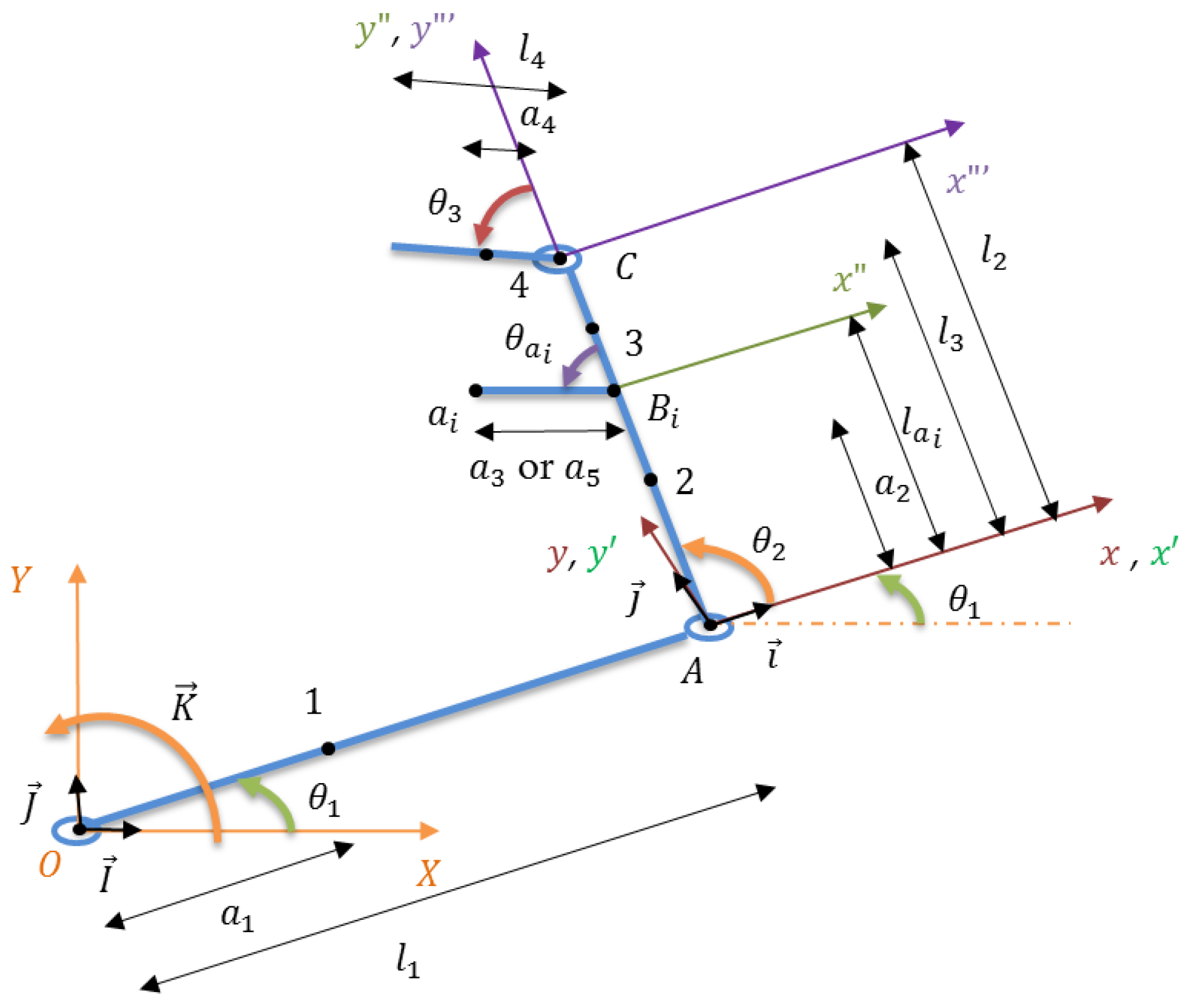
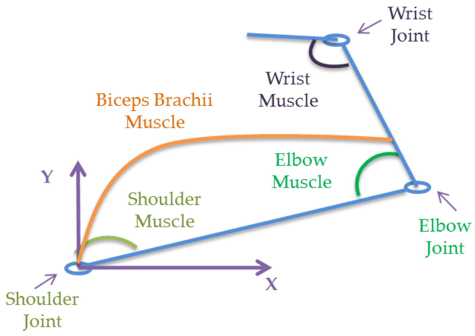
2.1. Hand Model
2.2. Equations of Motion
- Kinetic Energy
- Potential Energy
- Rayleigh dissipation function
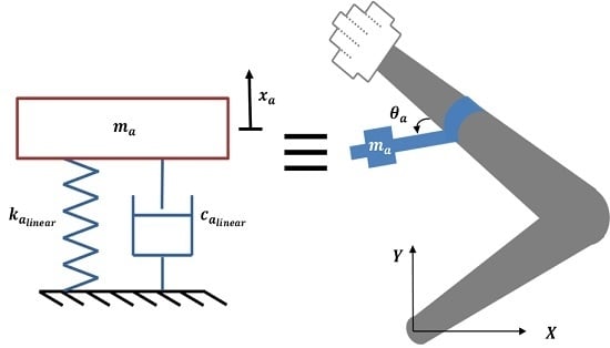
2.3. Absorber Design
3. Results and Discussions
3.1. Complex Transfer Function
3.2. Numerical Simulations
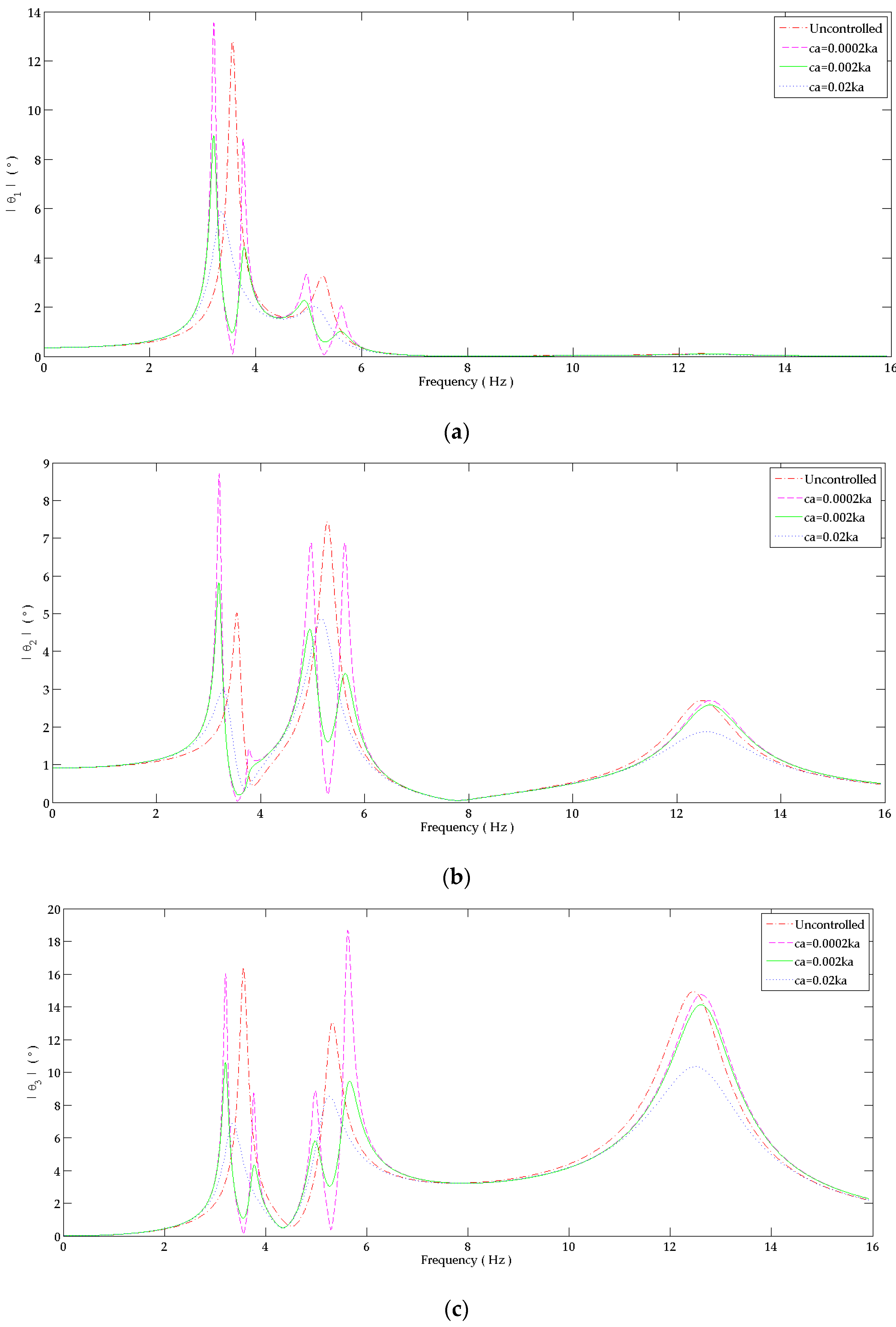
3.2.1. Behavior in Frequency Domain
- For the four DOF system with “absorber 1”:
- For the four DOF system with “absorber 2”:
- For the five DOF system with the “dual DVA”:
3.2.2. Behavior in Time Domain
3.3. Absorber’s Lifetime
4. Conclusions
Author Contributions
Conflicts of Interest
Appendix A
Abbreviations and Symbols
| Distance between centroid of the upper arm, forearm and the palm to its corresponding proximal joint (m) | |
| Position from the attached mass to the fixed joint of “absorber 1” and “absorber 2” (m) | |
| Base of absorber’s cantilevered beam and the attached mass (m) | |
| Damping coefficient matrix of the system (Nms/rd) | |
| Load, reliability, size, surface and temperature correction factors | |
| Bending damping coefficient of absorber’s beam and shoulder, elbow, biceps brachii and wrist muscles (Nms/rd) | |
| Linear damping coefficients of “absorber 1” and “absorber 2” (Ns/m) | |
| DBS | Deep brain stimulation |
| DOF | Degree of freedom |
| DVA | Dynamic vibration absorber |
| Modulus of elasticity of absorber’s beam material (GPa) | |
| Generalized conservative and frictional moments (Nm) | |
| Input moment at shoulder and wrist joints (Nm) | |
| Vector of bending moment functions (Nm) | |
| Height of absorber’s cantilevered beam and the attached mass (m) | |
| Complex transfer function (rd/Nm) | |
| Area moment of inertia of the beam (m4) | |
| Mass moment of inertia of the upper arm, forearm and the palm (kgm2/rd) | |
| Stiffness coefficient matric of the system (Nm/rd) | |
| Bending damping coefficient of absorber’s beam and shoulder, elbow, biceps brachii and wrist muscles (Nm/rd) | |
| Linear stiffness coefficients of “absorber 1” and “absorber 2” (N/m) | |
| Fatigue stress concentration factor | |
| Length of absorber’s cantilevered beam and the attached mass (m) | |
| Distance between absorber’s joint and controller device to the elbow joint (m) | |
| Distance from the location of concentrated masses of the upper arm, forearm and the palm to its corresponding proximal joint (m) | |
| Mass matrix of the system (kgm2/rd) | |
| Effective proof mass of “absorber 1” and “absorber 2” (kg) | |
| Mass attached to absorber’s beam (kg) | |
| Masses of the upper arm, forearm, controller device and the palm (kg) | |
| Total mass of the absorber (kg) | |
| Fatigue and yielding safety factors | |
| PD | Parkinson’s disease |
| Generalized coordinates of angular displacement and velocity (rd) and (rd/s) | |
| Raleigh dissipation function (J) | |
| Corrected and uncorrected endurance limit of the absorber’s beam (MPa) | |
| Ultimate and yielding strength of absorber’s beam (MPa) | |
| Proportional constant relating stiffness and damping coefficients | |
| Kinetic and potential energy of the system (J) | |
| Bending reaction moment on absorber’s beam (Nm) | |
| Receptance transfer function (rd/Nm) | |
| Angular displacement, velocity and acceleration functions (rd), (rd/s) and (rd/s2) | |
| Angular displacement magnitude (rd) | |
| Angular displacement magnitude of the controlled and uncontrolled systems (rd) | |
| Driving frequency (rd/s) | |
| Fundamental frequency of absorber’s system and its beam alone (rd/s) | |
| Natural frequency of the attached mass (rd) | |
| Natural frequency of the system (rd/s) | |
| Phase angle of the response () | |
| Bending stress (MPa) | |
| Damping ratio | |
| Density of the cantilevered beam of the absorber and the attached mass (kg/m3) |
References
- Miwa, H. Rodent models of tremor. Cerebellum 2007, 6, 66–72. [Google Scholar] [CrossRef] [PubMed]
- Kazi, S.; As’ Arry, A.; Zain, M.M.; Mailah, M.; Hussein, M. Experimental implementation of smart glove incorporating piezoelectric actuator for hand tremor control. WSEAS Trans. Syst. Control 2010, 5, 443–453. [Google Scholar]
- Morrison, S.; Kerr, G.; Silburn, P. Bilateral tremor relations in Parkinson’s disease: Effects of mechanical coupling and medication. Parkinsonism Relat. Disord. 2008, 14, 298–308. [Google Scholar] [CrossRef] [PubMed]
- Louis, E.D. Essential tremor. N. Engl. J. Med. 2001, 345, 887–891. [Google Scholar] [CrossRef] [PubMed]
- Reich, S. Common disorders of movement: Tremor and Parkinson’s disease. In Principles of Ambulatory Medicine, 4th ed.; Williams and Wilkins: Baltimore, MA, USA, 1995; pp. 1217–1229. [Google Scholar]
- Rocon, E.; Belda-Lois, J.M.; Sanchez-Lacuesta, J.J.; Pons, J.L. Pathological tremor management: Modelling, compensatory technology and evaluation. Technol. Disabil. 2004, 16, 3–18. [Google Scholar]
- Hariz, G.M.; Forsgren, L. Activities of daily living and quality of life in persons with newly diagnosed Parkinson’s disease according to subtype of disease, and in comparison to healthy controls. Acta Neurol. Scand. 2011, 123, 20–27. [Google Scholar] [CrossRef] [PubMed]
- Grimaldi, G.; Manto, M. Tremor: From pathogenesis to treatment. Synt. Lect. Biomed. Eng. 2008, 3, 1–212. [Google Scholar] [CrossRef]
- Hashemi, S.M.; Golnaraghi, M.F.; Patla, A.E. Tuned vibration absorber for suppression of rest tremor in Parkinson’s disease. Med. Biol. Eng. Comput. 2004, 42, 61–70. [Google Scholar] [CrossRef] [PubMed]
- Rahnavard, M.; Hashemi, M.; Farahmand, F.; Dizaji, A.F. Designing a hand rest tremor dynamic vibration absorber using H2 optimization method. J. Mech. Sci. Technol. 2014, 28, 1609–1614. [Google Scholar] [CrossRef]
- Igusa, T.; Xu, K. Vibration control using multiple tuned mass dampers. J. Sound Vib. 1994, 175, 491–503. [Google Scholar] [CrossRef]
- Brennan, M.J. Characteristics of a wideband vibration neutralizer. Noise Control Eng. J. 1997, 45, 201–207. [Google Scholar] [CrossRef]
- Drillis, R.; Contini, R.; Maurice Bluestein, M. Body segment parameters. Artif. Limbs 1964, 8, 44–66. [Google Scholar] [PubMed]
- Jeffcott, H.H. The Periods of Lateral Vibration of Loaded Shafts. The Rational Derivation of Dunkerley’s Empirical Rule for Determining Whirling Speeds. Proc. R. Soc. Lond. Ser. A 1918, 95, 106–115. [Google Scholar] [CrossRef]
- Hirsch, G.; Bachmann, H. Wind-induced vibrations. In Vibration Problems in Structures; Birkhäuser: Basel, Switzerland, 1995; pp. 73–112. [Google Scholar]


| Muscle | Shoulder | Elbow | Biceps | Wrist |
|---|---|---|---|---|
| k (Nm/rd) | 180 | 70 | 40 | 10 |
| c (Nms/rd) | 0.002 | 0.002 | 0.002 | 0.001 |
| Dimensions | L (cm) | H (cm) | B (cm) | |
|---|---|---|---|---|
| Absorber 1 | Beam 1 | 9 | 2.4 | 0.03 |
| Attached Mass 1 | 2.24 | 2.3 | 2.3 | |
| Absorber 2 | Beam 2 | 7.5 | 1.8 | 0.03 |
| Attached Mass 2 | 2.4 | 2 | 2 | |
| Parameters | (g) | (Nm/rd) | (Nms/rd) |
|---|---|---|---|
| Absorber 1 | 105.239 | 0.3184 | 0.0002 |
| Absorber 2 | 85.044 | 0.2662 | 0.0002 |
| Parameters | (g) | (N/m) | (Ns/m) |
|---|---|---|---|
| Absorber 1 | 105.239 | 52.78 | 0.0002 |
| Absorber 2 | 85.044 | 94.11 | 0.0002 |
| % Reduction | Absorber 1 | Absorber 2 | Dual DVA |
|---|---|---|---|
| Shoulder | 69.1%–79.7% | 12.6%–47.2% | 98.3%–99.5% |
| Elbow | 4.05%–32.12% | 72.6%–76.3% | 97.0%–97.3% |
| Wrist | 6.4%–44.2% | 40.2%–62.9% | 97.4%–97.5% |
| % Reduction | = 0.0002 | = 0.002 | = 0.02 |
|---|---|---|---|
| Shoulder | 98.3%–99.5% | 90.9%–93.9% | 65.24%–68.2% |
| Elbow | 97.0%–97.3% | 80.8%–85.4% | 49.7%–57.1% |
| Wrist | 97.4%–97.5% | 85.6%–85.9% | 54.1%–60.52% |
| Flexion Angle | Absorber 1 | Absorber 2 | Dual DVA | |
|---|---|---|---|---|
| Absorber 1 | Absorber 2 | |||
| 42.97 | 23.83 | 49.43 | 43.00 | |
| 61.45 | 61.81 | 49.96 | 43.53 | |
| Safety Factor | Absorber 1 | Absorber 2 | Dual DVA | |
|---|---|---|---|---|
| Absorber 1 | Absorber 2 | |||
| 1.07 | 0.69 | 1.77 | 1.64 | |
| 1.20 | 1.07 | 1.47 | 1.54 | |
| Safety Factor | Absorber 1 | Absorber 2 | |
|---|---|---|---|
| = 0.0002 | 42.97 | 23.83 | |
| 61.45 | 61.81 | ||
| = 0.002 | 40.81 | 18.69 | |
| 58.61 | 54.60 | ||
| = 0.02 | 14.78 | 5.64 | |
| 36.16 | 28.40 | ||
| Safety Factor | Absorber 1 | Absorber 2 | |
|---|---|---|---|
| = 0.0002 | 1.07 | 0.69 | |
| 1.20 | 1.07 | ||
| = 0.002 | 1.21 | 0.73 | |
| 1.25 | 1.21 | ||
| = 0.02 | 1.42 | 1.31 | |
| 2.00 | 2.43 | ||
© 2016 by the authors; licensee MDPI, Basel, Switzerland. This article is an open access article distributed under the terms and conditions of the Creative Commons Attribution (CC-BY) license (http://creativecommons.org/licenses/by/4.0/).
Share and Cite
Gebai, S.; Hammoud, M.; Hallal, A.; Khachfe, H. Tremor Reduction at the Palm of a Parkinson’s Patient Using Dynamic Vibration Absorber. Bioengineering 2016, 3, 18. https://doi.org/10.3390/bioengineering3030018
Gebai S, Hammoud M, Hallal A, Khachfe H. Tremor Reduction at the Palm of a Parkinson’s Patient Using Dynamic Vibration Absorber. Bioengineering. 2016; 3(3):18. https://doi.org/10.3390/bioengineering3030018
Chicago/Turabian StyleGebai, Sarah, Mohammad Hammoud, Ali Hallal, and Hassan Khachfe. 2016. "Tremor Reduction at the Palm of a Parkinson’s Patient Using Dynamic Vibration Absorber" Bioengineering 3, no. 3: 18. https://doi.org/10.3390/bioengineering3030018