1. Introduction
Modular implants are increasingly being used in hip revision arthroplasty [
1,
2], as it is possible to replace worn or damaged implant components without having to remove the ingrown components in the bone. This protects existing bone tissue and reduces operation time. The ceramic inlay, which has already been analyzed in a previous study [
3], and the ceramic head can be replaced. Manufacturers of hip implants recommend the use of metallic adapter sleeves for the revision of ceramic heads, as damaged surfaces on the stem taper can have a significant impact on the life span in situ of the implant [
4]. Adapter sleeves are also used for lengthening corrections or complications due to hip prosthesis dislocations [
5].
Damage to the stem taper may occur due to wear during use or removal of the old head. Surface damage or abrasion particles can cause punctual loads and the ceramic to break [
6]. Despite this disadvantage, ceramic hip implant components offer clear advantages, such as low wear compared to metal-on-polyethylene joint pairings and longer life span in situ [
7,
8]. Using metal adapter sleeves creates new optimal conditions for connecting the ceramic head and hip stem. The three components, the head, adapter sleeve and femoral stem are connected by a radial press fit. Current instructions from manufacturers [
4] recommend that the adapter sleeve should be placed first on the stem and connected to the taper with light pressure and a half turn. Next, the ceramic head is placed on top and joined with a hammer and one or several hammer impacts. The force for joining the three components is thus applied in a single-step process. The direction and amount of the applied force determine the connection stability [
9,
10,
11,
12]. The force applied varies depending on the surgeon [
13]. In a study involving 39 surgeons from German clinics, Nassutt et al. [
14] analyzed the axial taper forces of the ceramic head and hip stem connection in comparable situations. The forces varied between 273 N and 7848 N; the authors concluded that there is an urgent need to make the insertion method reproducible. Insufficient joining forces lead to inadequate joining connections, leading to premature loosening and micro-movement-induced corrosion or abrasion [
10]. Metal abrasion at the junctions of the modular implants is assumed to be a reason for the failure of total hip replacements [
15,
16]. Forces that are too high pose a risk of fractures of the surrounding bone [
17] or breakage of ceramic implant components.
Several studies showed that the joining force has the most significant influence on the taper connection, followed by other factors such as the contact situation (e.g., contamination such as fat [
18]), the head material [
11,
19] or the design of the implant [
20]. However, the most significant factors influencing the assurance of a secure taper connection are the joining process and the surgical technique [
21,
22].
Optimal and consistent conditions during the joining of hip implant components can minimize risks such as ceramic fractures, metal abrasion at the taper connection or fractures of the surrounding bone. This can lead to an increase in the life span in situ of the implant. The new modified procedure of joining investigated could contribute to the standardization of the surgical technique, which makes the joining force applied independent of the surgeon, reduces or saves costs for follow-up operations and has a positive effect on the patient’s quality of life. This experimental study under laboratory conditions aimed to analyze the influence of a modified joining procedure on the joint strength of the ceramic head, adapter sleeve and hip stem. The question was how reproducible joining in two individual steps with a constant joining force affects the press-fit connections. A new process was developed, which connected the adapter sleeve to the ceramic head in the first step and these two components to the stem taper in the second step. The combination of an instrument and a new assembly device applied a reproducible joining force of 2 kN in both the process steps. The pull-off forces of these connections were compared with the pull-off forces of the components that were joined under optimal conditions using a testing machine. Furthermore, the measurement deviations of the forces were compared with those from previous studies in the literature.
2. Materials and Methods
The investigations were carried out as part of a BMBF project called “Smart-I” together with the implant and instrument manufacturers (see the acknowledgments). The participating companies provided both the CAD data and the test components. A 32 mm ceramys revision head from Mathys Orthopädie GmbH (Mörsdorf, Germany) and a BioBall adapter sleeve 12/14 standard, neck length L from Merete GmbH (Berlin, Germany) were examined. These were combined with a 12/14 stem taper, which was specially adapted and manufactured for the project by Aristotech Industries GmbH (Luckenwalde, Germany). The part of the femoral stem located in the bone was removed to simplify the mounts for the experiments (see
Figure 1). The revision head was made of alumina-toughened zirconia (ceramys
®, Mathys Orthopädie GmbH, Mörsdorf, Germany), and the taper and the BioBall adapter sleeve were made of Ti6Al4V.
2.1. Concept of the Two-Step Joining Procedure
The new concept to be investigated was that the head, adapter sleeve and stem taper joining process should be carried out in two separate process steps. The same reproducible joining force was applied in both steps. First, the adapter sleeve was pressed into the head and in the second step, these two components were joined together on the stem taper.
To connect the adapter sleeve and head, an existing assembly device from Mathys [
23] was adapted to press the sleeve into the head with 2 kN (see
Figure 2a—CAD planning of the first joining step). Optimal, straight alignment during the joining process was achieved by inserting the head into a holder adapted to the outer contour, which allowed small, self-aligning movements of the head in the holder. An integrated O-ring held the head in the holder, which allowed compensating movements. When the lever of the device was turned, the axle moved downwards. At the end of this axle was a counterpart that was precisely adapted to the inner contour of the adapter sleeve so the ball could be self-centered and axially aligned. The force was applied to the upper edge of the adapter sleeve by manually turning the lever until the target force of 2 kN was reached.
The ceramic head and the revision adapter sleeve were joined to the taper of the hip stem using an instrument designed by Endocon GmbH (Wiesenbach, Germany), which applied a reproducible, pulse-controlled joining force and was already available on the market under the brand name safeConnect
® [
24] (see
Figure 2b). The impulse of the instrument was adjusted to a maximum force of 2 kN for these tests to comply with the force specified in the ISO 7206-10 test standard [
25]. In this step, the pre-assembled components, adapter sleeve and ceramic head were placed manually on the taper of the hip stem. The instrument was then placed axially on the top of the head and the impulse was triggered by pressing on the instrument, which connected the components with each other through the impulse controlled force.
2.2. Impacting and Pull-Off Tests
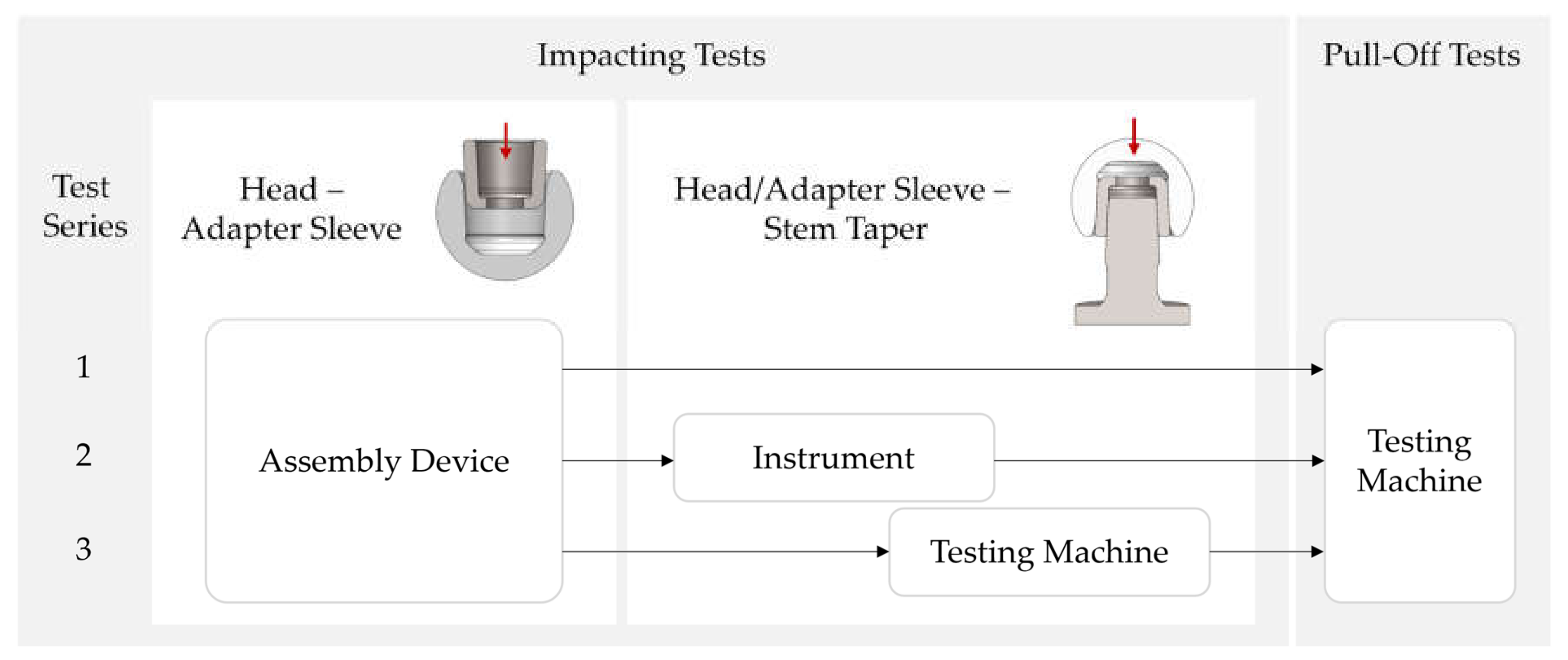
In order to test the concept of joining in two steps with reproducible force application, the following test plan (see
Figure 3) was worked out:
Test series 1: Joining of adapter sleeve in head with the assembly device and pull-off tests with the testing machine;
Test series 2: Joining of adapter sleeve and head with assembly device and manual impacting of these two components with the instrument onto the stem taper; pull-off tests with the testing machine;
Test series 3: Joining of adapter sleeve and head with assembly device and impacting of these two components onto the stem taper with the testing machine according to ISO 7206-10 [
25]; pull-off tests with the testing machine.
To evaluate the reproducibility of the new joining concept, a comparison of the pull-off forces of test series 2 and 3 was carried out. A t-test of the two samples was performed to evaluate the significance. The aim of test series 1 was to find out which of the two press-fit connections was the first to loosen during the pull-off tests.
A new set of components was available for each test series. Due to the expected plastic deformation on the press-fit surfaces during the first joining process [
26], the first test was excluded from the evaluation. The components were cleaned of possible abrasion residues and dried between the individual tests. All components were positioned by hand, as straight as possible and without pressure, before the impaction force was applied using the assembly device, instrument or testing machine.
To realize the joining process of head and adapter sleeve reproducibly with 2 kN, a sensor was added to the assembly device from Mathys. In accordance with the desired measuring range, a load cell with ball support (KMM60-10 kN) including measuring amplifier (IMA2-DMS) from Inelta Sensorsysteme GmbH & Co. KG (Taufkirchen, Germany) was mounted below the ceramic head holder. The sensor data was read out via a multifunctional DAQ device (USB-6009, National Instruments Corporation, Austin, TX, USA), which additionally served as an interface to the PC (see
Figure 4). Finally, the measured values were visualized using a specially developed LabVIEW code (National Instruments Corporation, Austin, TX, USA) to terminate the manual joining process when the target force was reached.
When joining with the instrument (test series 2), the force was transferred to the components via a pulse triggered in the handpiece. For this purpose, the stem taper was connected to a force transducer via a thread. With this piezoelectric force transducer, a force–time curve could be recorded to determine the maximum force (see
Figure 5). The assembly was embedded in a fixture that stood straight on the floor via a plate to exclude damping from underground. The test setup and an exemplary force–time curve for the joining process can be seen in
Figure 5.
A tensile/compression/torsion testing machine from DYNA-MESS Prüfsysteme GmbH, Aachen, Germany, was used to join the assembly ceramic head/adapter sleeve and the stem taper in test series 3 and to pull off all the assemblies. Impacting and pull-off tests were carried out in accordance with ISO 7206-10 [
25] at a test speed of 0.04 mm/s.
Figure 6 shows the test setups for impacting and pull-off.
The results were statistically analyzed and graphically displayed using OriginPro 2023 software (OriginLab, Northampton, MA, USA). To evaluate the influence of the new joining procedure, a two-sample independent t-test (hypothesis test) was used to determine whether the mean values of our two samples differed significantly from each other. The significance level was .
3. Results
For the insertion of the adapter sleeve into the head with the modified assembly device, the mean value was 2030 N with a standard deviation of approx. 22 N. The mean value for the pull-off test was 1546 N, with a standard deviation of 77 N. No outliers were detected. The measured values are listed in
Table 1.
The measured values of test series 2 and 3 are summarized in
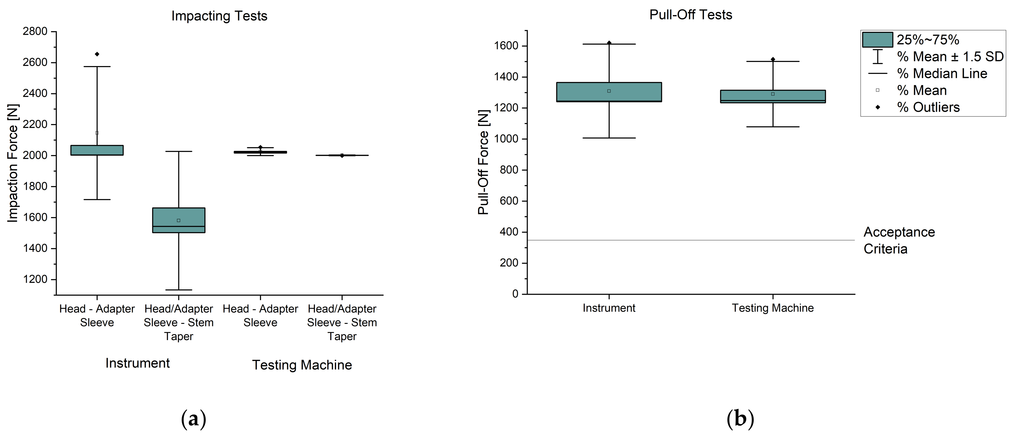
Table 2. The mean value for joining the adapter sleeve into the head from test series 2 was approx. 2146 N and for test series 3 approx. 2026 N, whereby the standard deviation of test series 3 for the testing machine was lower. This was because the fifth test in series 2 was an outlier. The average impaction forces connecting the head/adapter sleeve and the stem taper were approx. 1581 N for the instrument (test series 2). This resulted in a standard deviation of approx. 298 N. In contrast, the test machine could join with an impacting force of 2002 N and the standard deviation was only 1.4 N (test series 3). When removing the head from the taper stem, an average pull-off force of approx. 1309 N was achieved for the components joined by the instrument and the average measured values for the components joined by the testing machine were 1290 N. The standard deviation for the pull-off forces for the instrument was approx. 202 N and for the testing machine lower at approx. 140 N. In all the tests, the adapter sleeve and head always detached together from the stem taper.
Although the measured difference between the impacting and pull-off forces of the head/adapter sleeve on the taper stem was higher for the instrument than for the testing machine, the release forces of the tests with the instrument were higher on average than with the testing machine. However, they only differed by approx. 19 N, which was within the standard deviation determined. The difference between the two average pull-off forces of test series 2 and 3 was not significant for a significance level of 0.05 and a p-value of 0.87 ().
The ISO 7206-10 standard [
25] does not specify any minimum requirements for pull-off forces. Therefore, the internal acceptance criterion for the pull-off forces was set at 350 N in the project. This requirement was met for all the tests. The results are shown below in two boxplot diagrams (see
Figure 7).
4. Discussion
In several studies in surgical treatment with total hip endoprostheses, the use of devices is described as necessary for a more reproducible joining process [
11,
12,
20], as the long-term success of such an operation primarily depends on the surgical technique. One parameter that significantly influences the quality of the connection is the impaction force [
10,
27,
28].
Ceramic–ceramic friction partners are often used in total hip arthroplasty, as they generate minor abrasion and therefore have a longer service life. However, the ceramic components place high demands on the joining process to prevent ceramic fracture. For revision operations, adapter sleeves are used to create a new, smooth surface between the ceramic head and stem taper, thus preventing stress peaks caused by abrasion particles. This creates a second joining connection on the modular implant, which offers additional potential for errors. Current handling instructions and the instruments mainly used leave plenty of scope for variations in the impaction force applied to connect the three implant components.
To make the joining process of a ceramic head reproducible during a revision operation using an adapter sleeve, our study investigated a modified procedure in two process steps with a constant impaction force. In the first step, the adapter sleeve was joined to the ceramic head with 2 kN and in the second step, these two components were pressed on the taper of the hip stem with an instrument that generated a reproducible force pulse of 2 kN.
By following this new joining procedure, the adapter sleeve and head detached from the stem taper first in all the pull-off tests. The connection between the adapter sleeve and head remained intact. The pull-off forces of the adapter sleeve and head from test series 1 also confirmed this, which at an average of 1546 N were higher than the pull-off forces and from test series 2 and 3. When joining the adapter sleeve to the head, there was an upward outlier (test no. 5 on the instrument) caused by inattention. The measured impaction force of the head/adapter sleeve on the stem taper was also higher than the previous tests. However, this was not reflected in the pull-off force, so this could be neglected. An additional mechanical impaction force limitation, like a stopper on the assembly device, would make this joining step more reproducible and reduce the possibility of outliers.
The release forces
of the components joined with the instrument were approximately the same as for the test components assembled with the testing machine (
). However, the measured impacting forces
on the instrument did not reach 2 kN (they were on average 1580.5 N). It is assumed that this was due to the damping behavior of the test setup (the environment) [
14,
29]. As the instrument was a product available on the market and calibrated by Endocon GmbH, it was expected that the instrument applied the joining force of 2 kN. The results of the pull-off forces seemed to confirm this assumption. The standard deviation of the impaction forces was significantly higher for the instrument at 298 N than for the testing machine at 1.4 N (
). This was an expected result, as the testing machine was regulated to a target force of 2 kN. In a study by Nassutt et al. [
14], the mean measured forces during joining by different test persons were
. Wendler et al. [
13] determined forces of
. These studies show that the standard deviation for the impaction forces on conventional joining methods is significantly higher than in our tests with the instrument and the previously joined head/adapter sleeve assembly. The surgeons in the study by Nassutt et al. carried out 3–5 tests in their own test series and the standard deviation varied between 21 and 1414 N. This indicates that some surgeons generate repetitive reproducible joining forces while others have a more significant variation. For inexperienced surgeons in particular, the new workflow with assembly device and instrument could generate consistent impacting forces and thus mean a more reproducible application of force. The study also described that some surgeons were reluctant to hammer on the ceramic head. This is why joining forces below 2 kN were measured. With such low forces, the risk of metal abrasion or micro-movement-induced corrosion at the taper connection is higher than with greater impaction forces, which the new, reproducible joining procedure could prevent.
All joined connections achieved a pull-off force
and therefore fulfilled the acceptance criterion in our study. The test series’ measured pull-off forces confirmed previous studies on ceramic revision heads using adapter sleeves [
30]. With the standard deviations of the pull-off forces
and
of the instrument and testing machine, there was only a difference of approx. 60 N. The mean values of the two test series did not differ significantly (hypothesis test), which showed that the new joining procedure could withstand joining under almost optimal conditions such as the testing machine. As there is a linear relationship between the impaction force and the pull-off force for conical press-fit connections [
10], it is reasonable to assume that the pull-off force is reproducible if the impaction force is applied at a constant level. However, this should be confirmed by further investigations with different applicants, as no data were found in the literature that would allow a comparison with our recorded data (same joining force of 2 kN, use of a ceramic head, evaluation of the standard deviation).
In this study, the influence of the angled positioning of the head/adapter sleeve connection on the stem taper was not an object of investigation. Attention was paid to ensuring that the alignment was as straight as possible by one test person and that the connection surfaces were dry and free of particles. One study shows that the best joint quality depends, among other factors, on an ideally straight alignment of the joining components to each other [
21]. In their study, Ouellette et al. [
29] described that the head taper connection aligns itself during insertion. To evaluate the influence of the modified joining procedure, tests should be carried out with different test persons under more realistic conditions. It must be verified whether an ideally straight load application during an operation is always feasible due to the accessibility. Other questions are at what angle the impulse of the instrument can still be triggered, how high the force losses are, and what influence this has on the connection quality. The impaction forces are divided into horizontal and vertical components with angular misalignment so that the resulting force becomes smaller the larger the angle of entry. Furthermore, some studies describe a force of 4 kN as the optimum impaction force for head taper [
10,
28,
29,
31,
32], although the ISO 7206-10 [
25] recommends a force of 2 kN. Various conditions influence the forces applied to the joint connection, such as the stiffness of the impact tip of the instrument [
29] or the implant component size [
33], so further investigations and detailed dimensioning are required to define the optimum joining force. Compensation could be achieved by using different tips or an adjustable force range of the instrument.
Another limitation of this study is that the pull-off forces of impulse-joined components were compared with quasi-statically joined parts. Wade et al. [
21] concluded that the connection quality of quasi-statically joined components is the best, so a comparison with almost optimally quasi-statically joined parts using a testing machine seemed reasonable in our case. However, an impulse-joined test setup [
31] would be preferable for more precise comparability of the results for further investigations. The influence of the environment on the connection quality as an attenuating component was also not investigated in detail in this study. Some studies on this have come to different conclusions [
13,
31]. The number of test samples available for the experiments was limited. A larger number would have provided further statistical support. Furthermore, only one head, adapter sleeve and stem taper size were analyzed, and the tests were carried out under simplified conditions in the laboratory.

 ,
, 


