
Feasibility of a Shape-Memory-Alloy-Actuator System for Modular Acetabular Cups
 , ,
, ,
Abstract
:
1. Introduction
2. Materials and Methods
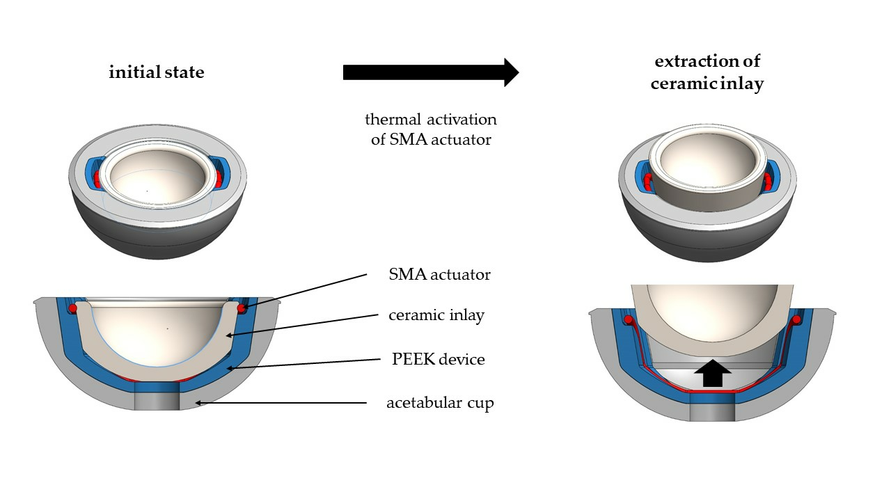
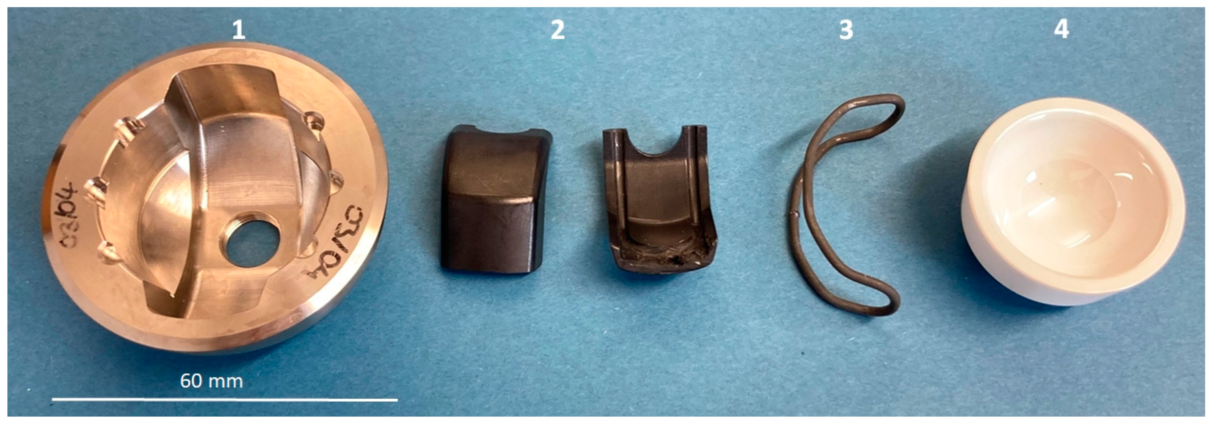
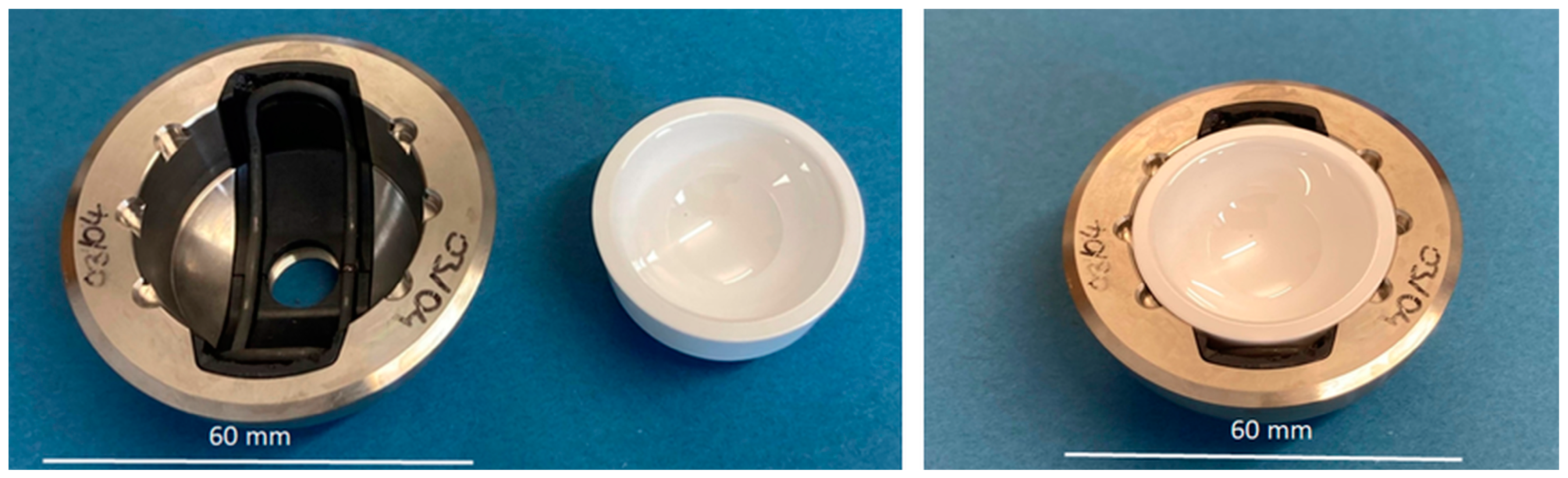
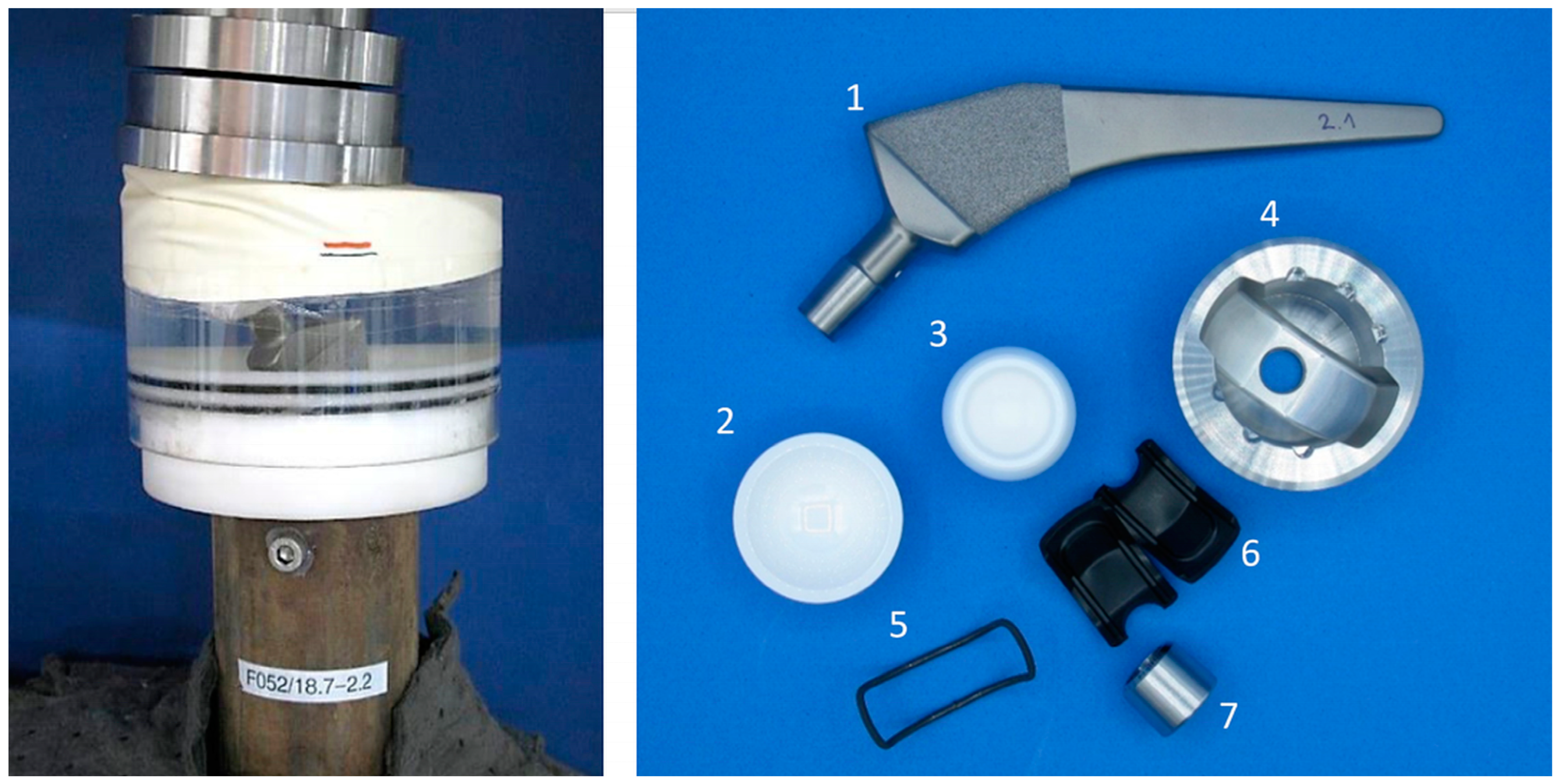
2.1. Overview Implant Components
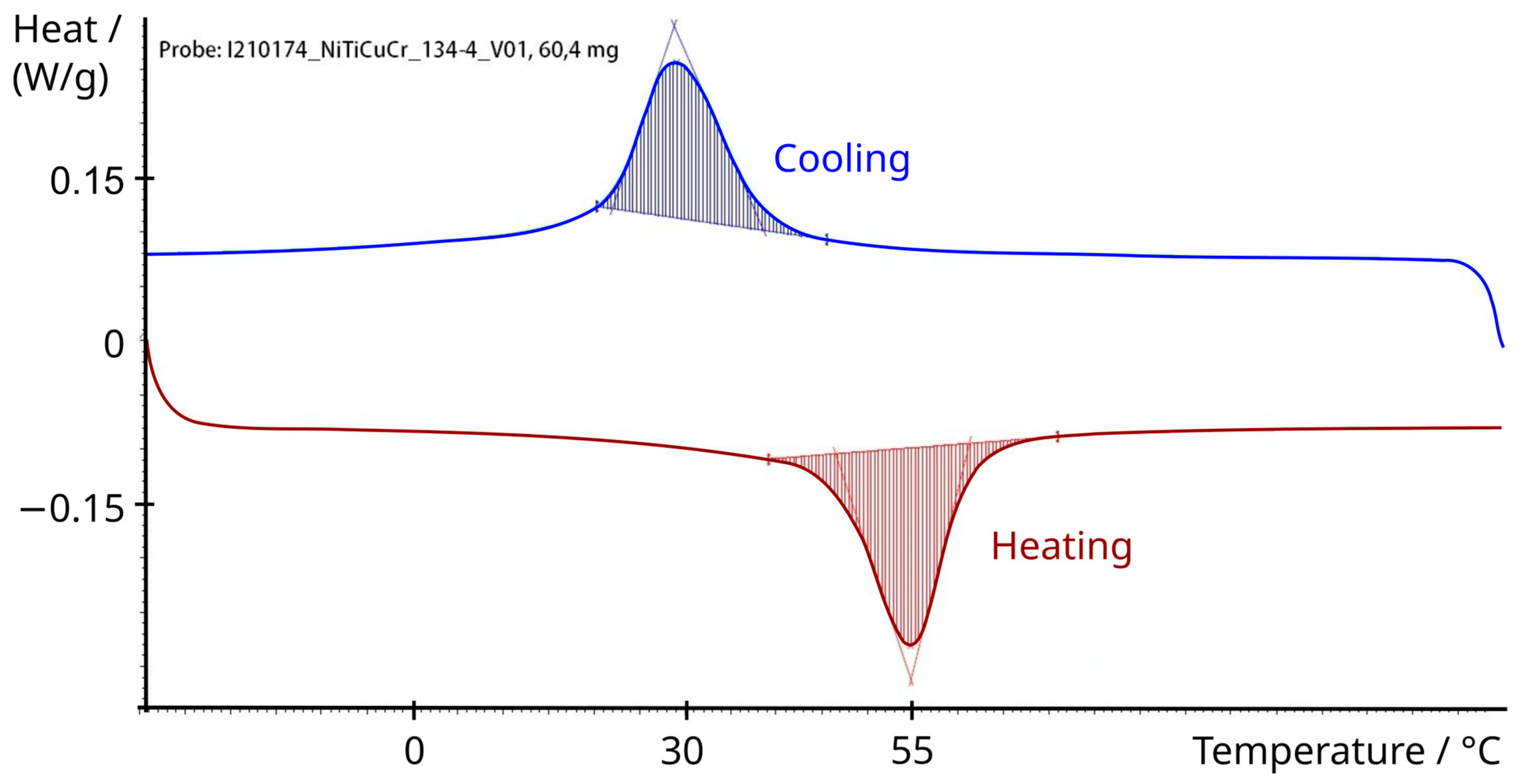
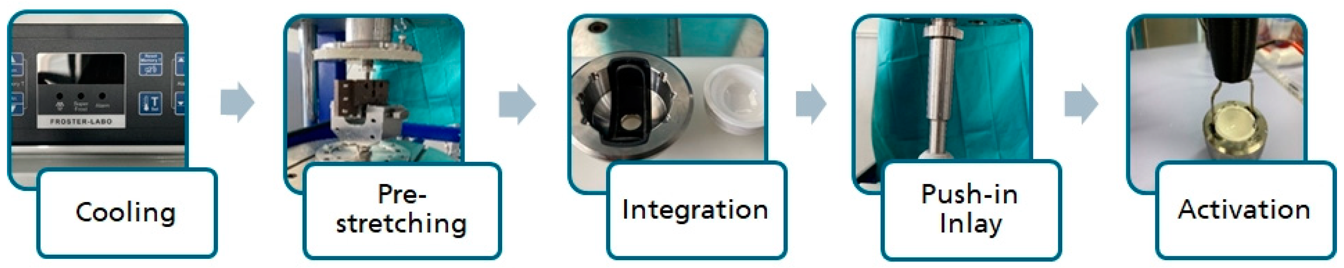
2.2. Shape Memory Alloy Actuator
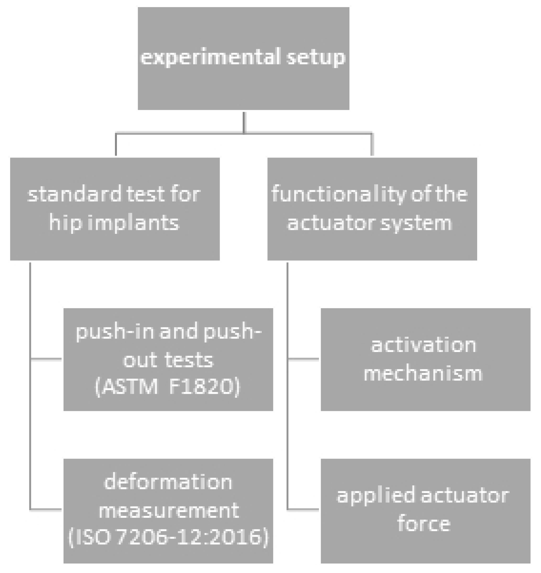
2.3. Experimental Setup
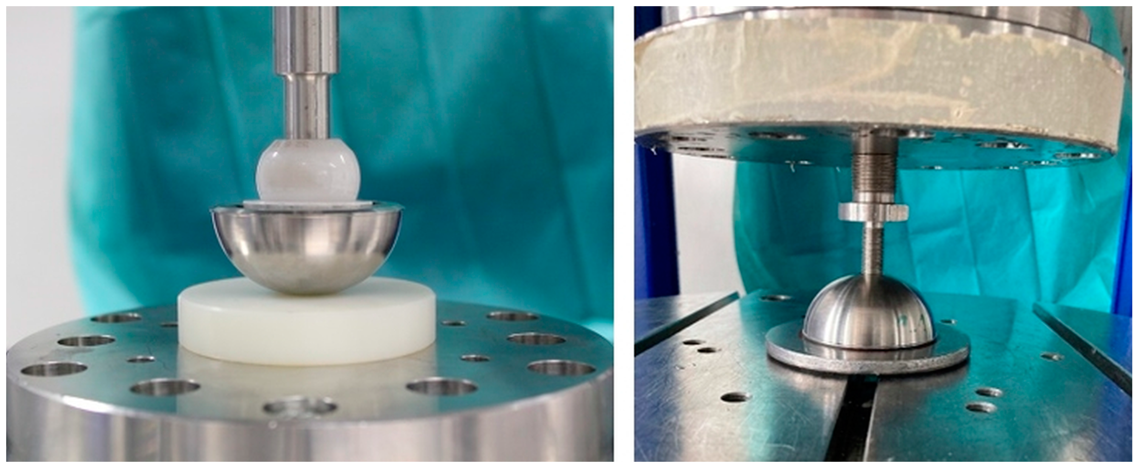
2.3.1. Push-In and Push-Out Tests for Acetabular Cups
2.3.2. Deformation Measurement of Acetabular Cups with and without the Ceramic Inlay
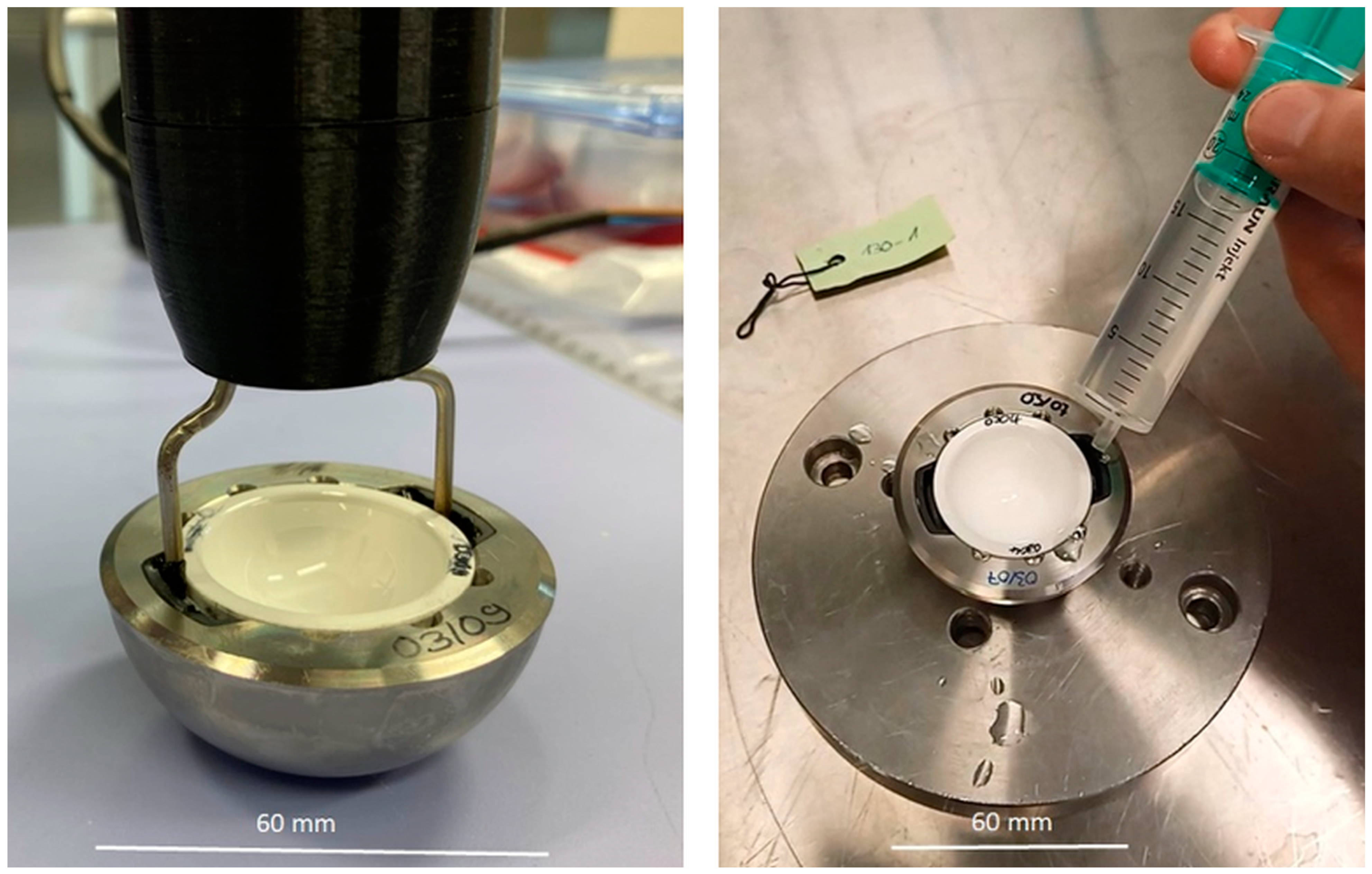
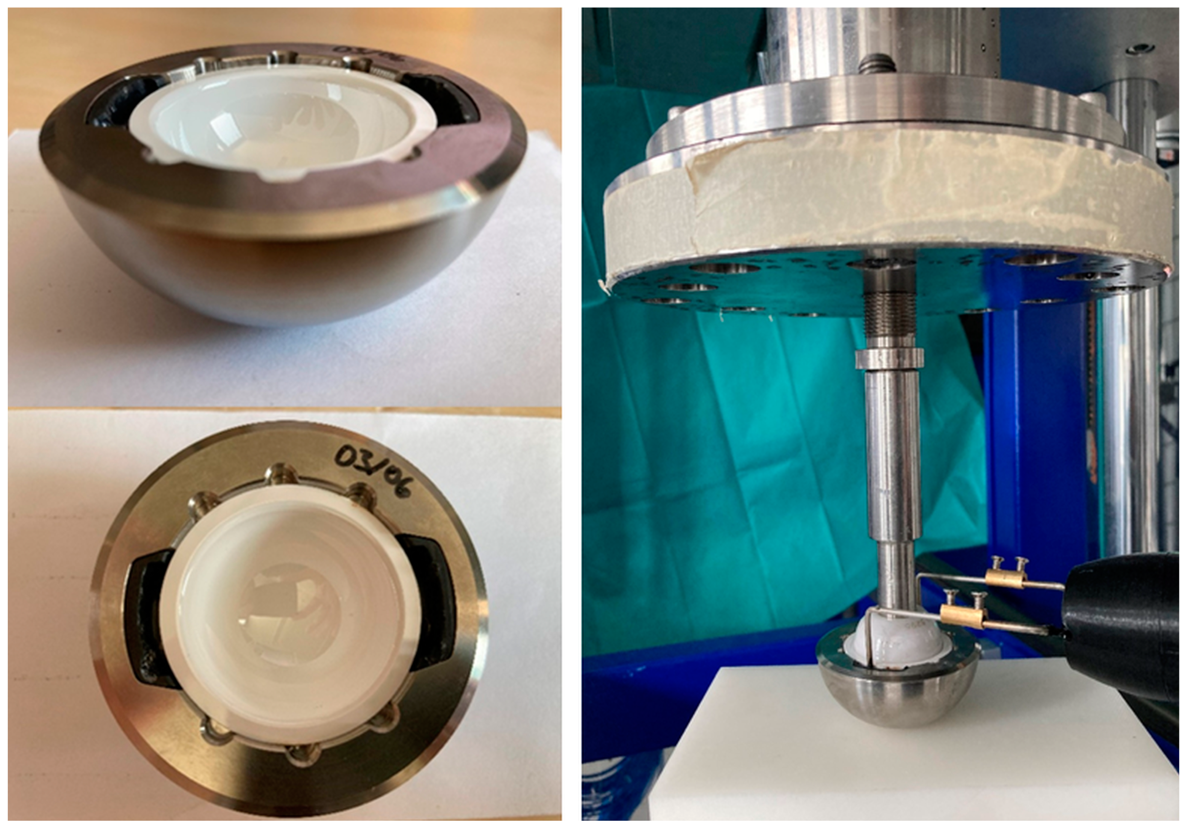
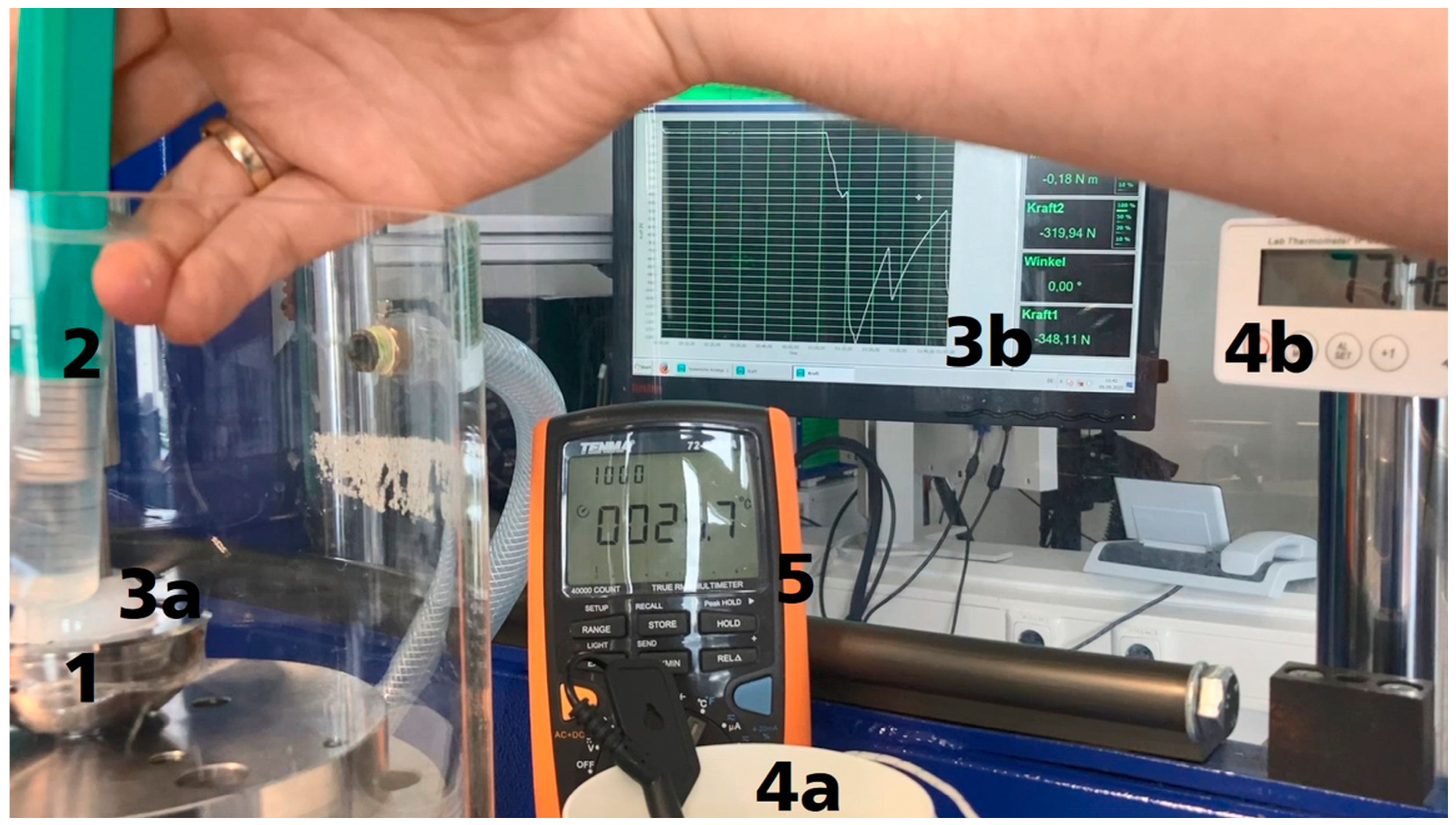
2.3.3. Functionality of the Actuator System
3. Results
3.1. Push-In and Push-Out Tests for Acetabular Cups
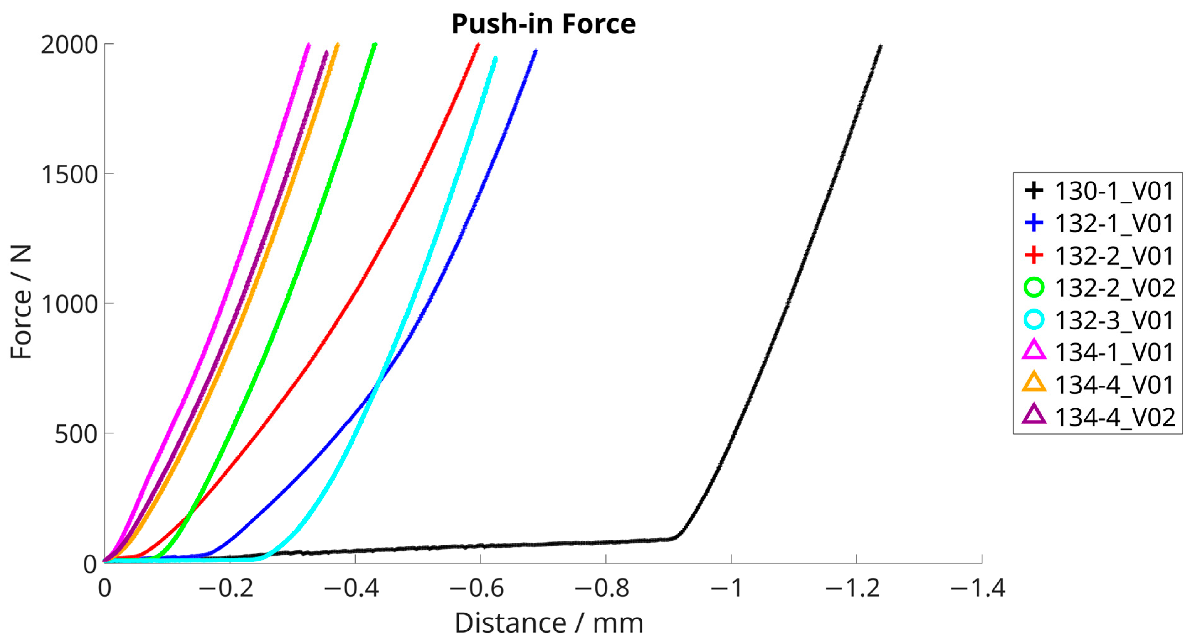
3.1.1. Push-In Tests
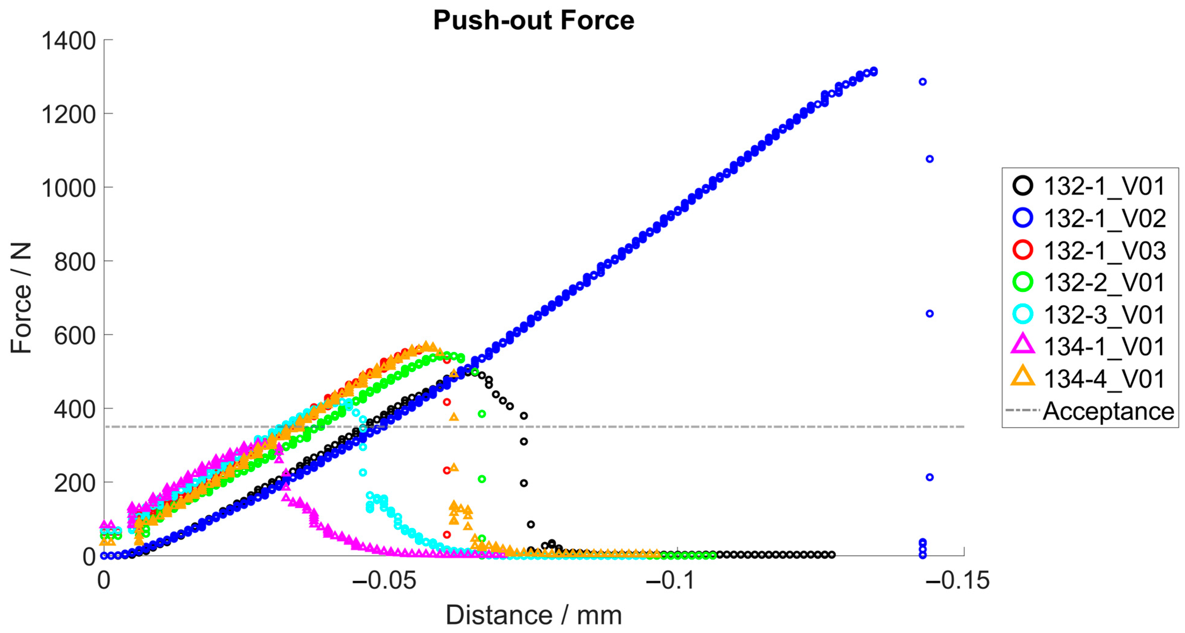
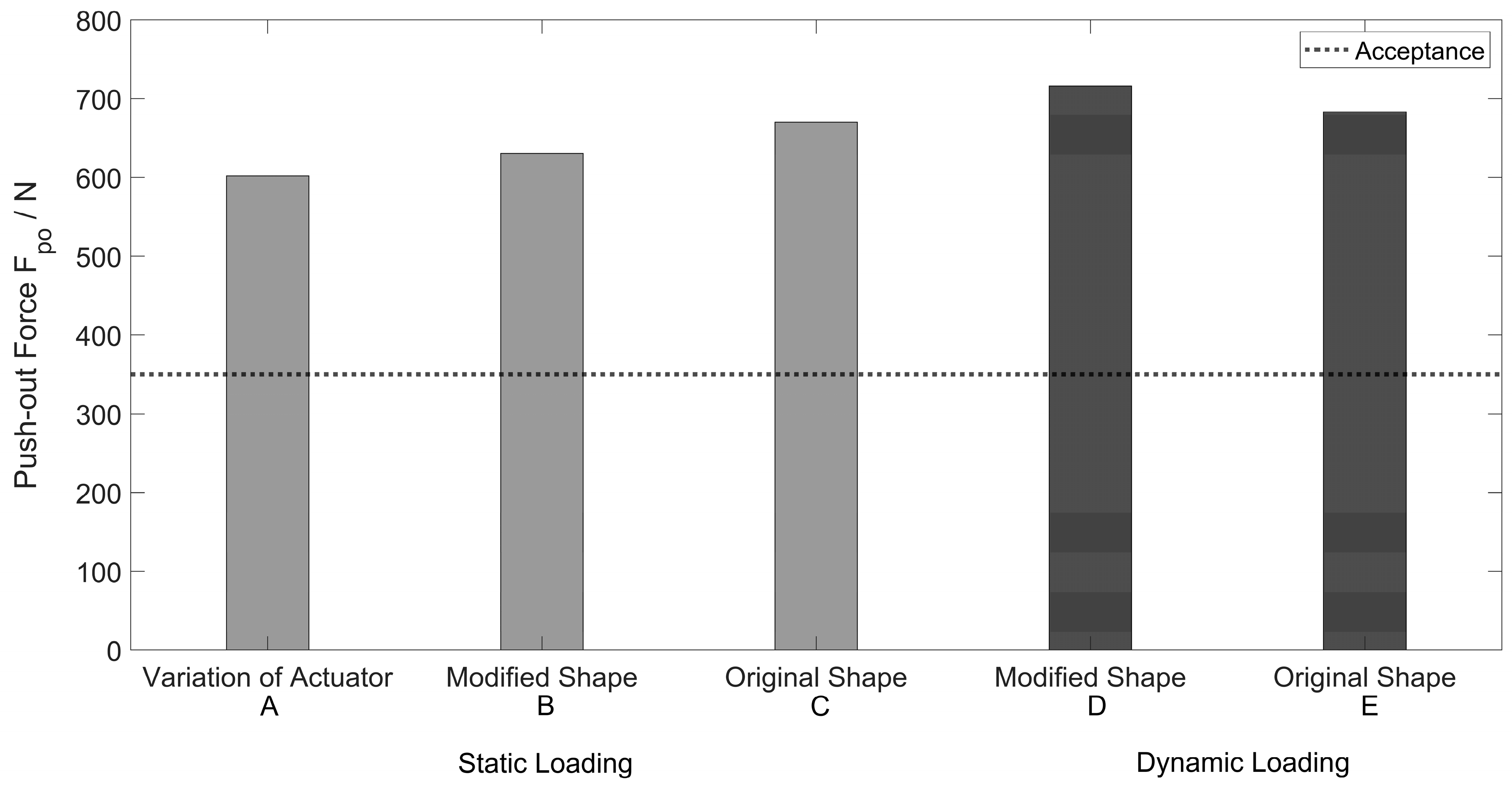
3.1.2. Push-Out Tests
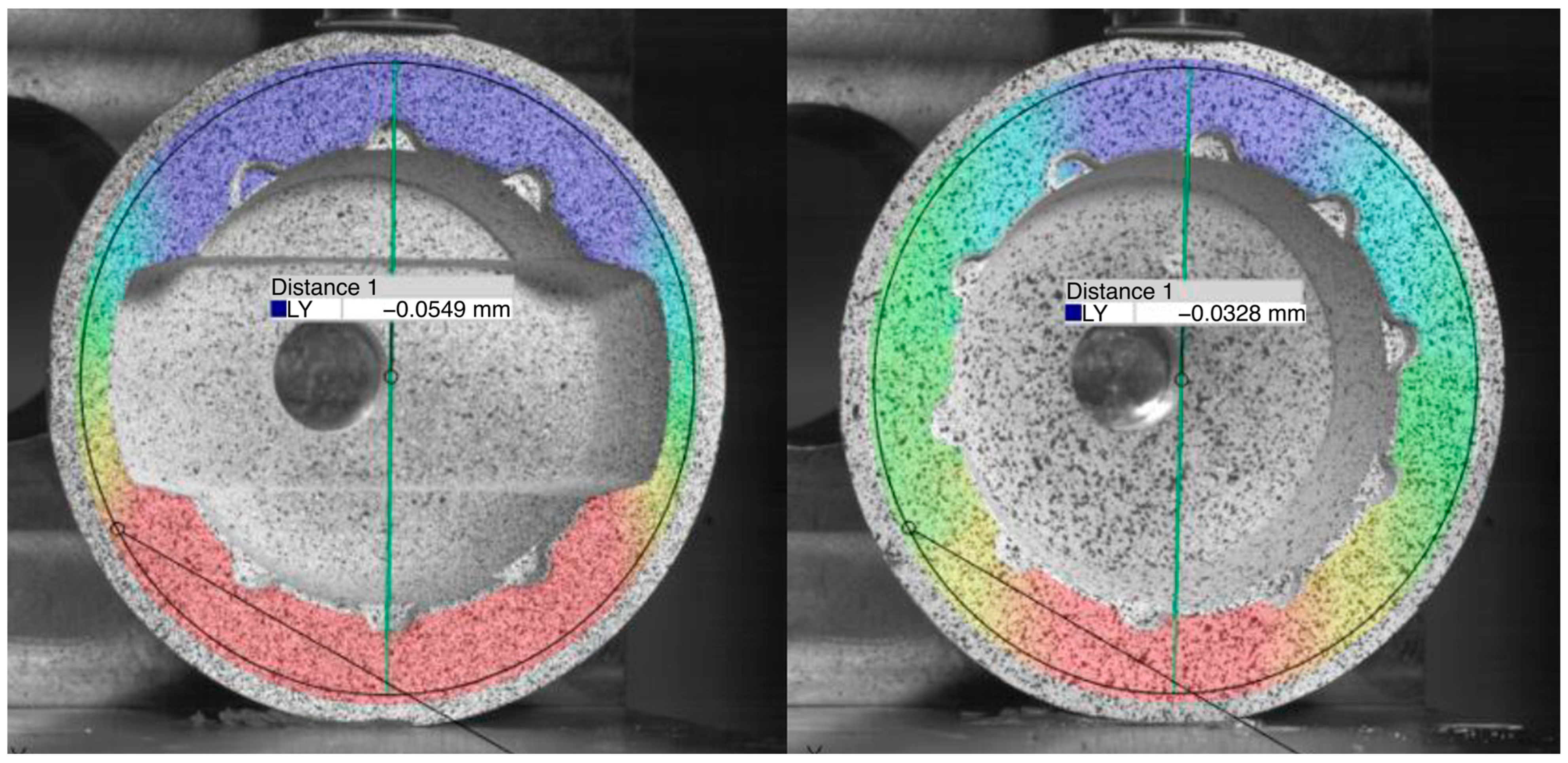
3.2. Deformation Measurement of Acetabular Cups with and without the Ceramic Inlay
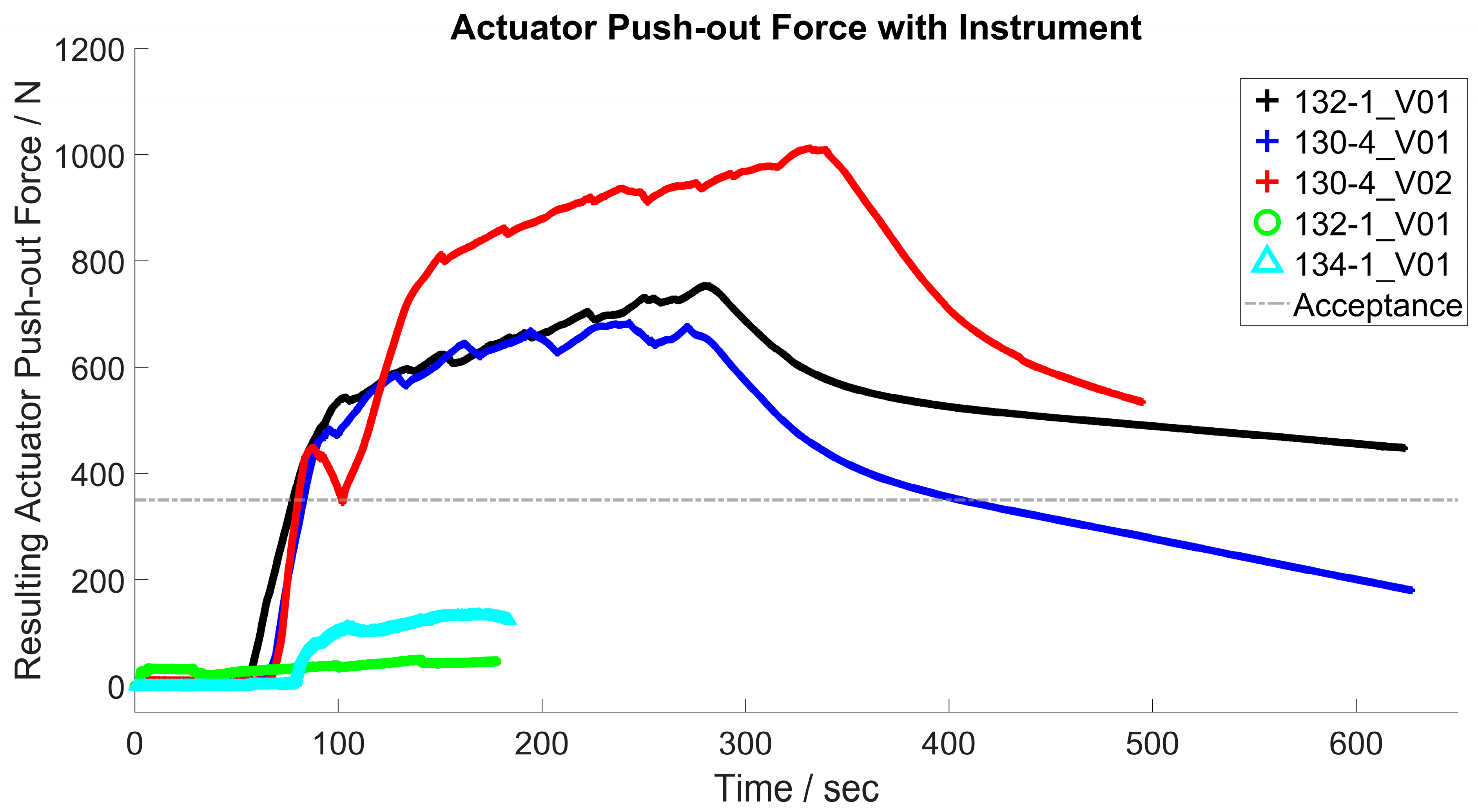
3.3. Functionality of the ACTUATOR system
3.3.1. Activation with Electric Current
3.3.2. Activation with Hot Water
4. Discussion
4.1. Push-In and Push-Out Tests
4.2. Deformation Measurement of Acetabular Cups with and without the Ceramic Inlay
4.3. Functionality of the Actuator System
5. Conclusions
Author Contributions
Funding
Institutional Review Board Statement
Informed Consent Statement
Data Availability Statement
Acknowledgments
Conflicts of Interest
References
- Giuseppe, M.; Mattia, B.; Nadia, B.; Raffaele, V.; Pasquale, R.; Stefano, D.A.; Mattia, S.; Vincenzo, D.S.; Giulio, M. Ceramic-on-ceramic versus ceramic-on-polyethylene in total hip arthroplasty: A comparative study at a minimum of 13 years follow-up. BMC Musculoskelet. Disord. 2022, 22, 1062. [Google Scholar] [CrossRef]
- El-Desouky, I.I.; Helal, A.H.; Mansour, A.M.R. Ten-year survival of ceramic-on-ceramic total hip arthroplasty in patients younger than 60 years: A systematic review and meta-analysis. J. Orthop. Surg. Res. 2021, 16, 679. [Google Scholar] [CrossRef] [PubMed]
- Zhang, X.; Zhang, Y.; Jin, Z. A review of the bio-tribology of medical devices. Friction 2022, 10, 4–30. [Google Scholar] [CrossRef]
- Morlock, M.M.; Bishop, N.; Kaddick, C. Welche Hüftgelenkgleitpaarung für welchen Patienten? Tribologie der Zukunft. Der Orthopäde 2011, 40, 1061–1067. [Google Scholar] [CrossRef] [PubMed]
- Rehmer, A.; Bishop, N.E.; Morlock, M.M. Influence of assembly procedure and material combination on the strength of the taper connection at the head-neck junction of modular hip endoprostheses. Clin. Biomech. 2012, 27, 77–83. [Google Scholar] [CrossRef]
- Weber, P.; Steinbrück, A.; Paulus, A.C.; Woiczinski, M.; Schmidutz, F.; Fottner, A.; Jansson, V. Gelenkteilwechsel in der Hüftarthroplastik: Was dürfen wir kombinieren? Der Orthopäde 2017, 46, 142–147. [Google Scholar] [CrossRef]
- Pitto, R.P. Pearls: How to Remove a Ceramic Liner from a Well-fixed Acetabular Component. Clin. Orthop. Relat. Res. 2016, 474, 25–26. [Google Scholar] [CrossRef]
- Whiting, F.; Lewis, C. A simple technique for ceramic liner extraction during revision total hip arthroplasty. Ann. R. Coll. Surg. Engl. 2014, 96, 549–550. [Google Scholar] [CrossRef]
- Gurung, B.; Shah, O.A.; Edwards, T.C.; Afzal, I.; Gikas, P.D.; Field, R.E. A Simple Technique to Remove an Incarcerated Ceramic Liner in Revision Hip Arthroplasty. Arthroplast. Today 2023, 21, 101142. [Google Scholar] [CrossRef]
- endocon GmbH. OrthoClast (R) Accessories—Efficient Removal of Ceramic Inlays: FR-063 Ceramic-Inlay Tappet. Available online: https://www.endocon.de/endocon-specialist-instruments-arthroplasty.html (accessed on 12 June 2023).
- Cucchi, D.; Gathen, M.; Streicher, R.; Wirtz, D.C. Keramik-Keramik-Gleitpaarung in der Revisionsendoprothetik des Hüftgelenks. Z. Orthop. Unfall. 2018, 156, 272–280. [Google Scholar] [CrossRef]
- Gallo, J.; Goodman, S.B.; Lostak, J.; Janout, M. Advantages and disadvantages of ceramic on ceramic total hip arthroplasty: A review. Biomed. Pap. Med. Fac. Univ. Palacky Olomouc Czech. Repub. 2012, 156, 204–212. [Google Scholar] [CrossRef] [PubMed]
- Ferguson, D.; Metcalf, R. Extraction of a well fixed but fractured ceramic acetabular liner. Arthroplast. Today 2015, 1, 11–13. [Google Scholar] [CrossRef] [PubMed]
- ASTM F 1820; Standard Test Method for Determining the Forces for Disassembly of Modular Acetabular Devices, 11.040.40. American Society for Testing and Materials: West Conshohocken, PA, USA, 2022.
- ISO 7206-12; ISO Implants for Surgery. Partial and Total Hip Joint Prostheses. Deformation Test Method for Acetabular Shells, 11.040.40. International Organization for Standardization: Geneva, Switzerland, 2016.
- Hamann, I.; Gebhardt, F.; Eisenhut, M.; Koch, P.; Thielsch, J.; Rotsch, C.; Drossel, W.-G.; Heyde, C.-E.; Leimert, M. Investigation into the Hybrid Production of a Superelastic Shape Memory Alloy with Additively Manufactured Structures for Medical Implants. Materials 2021, 14, 3098. [Google Scholar] [CrossRef] [PubMed]
- Wagner, M.E.H.; Rotsch, C.; Hanus, S.; Essig, H.; Grunert, R.; Gellrich, N.-C.; Lichtenstein, J. Feasibility of implants with superelastic behaviour for midface reconstruction. J. Biomater. Appl. 2020, 34, 1449–1457. [Google Scholar] [CrossRef] [PubMed]
- Werner, M.; Hammer, N.; Rotsch, C.; Berthold, I.; Leimert, M. Experimental validation of adaptive pedicle screws-a novel implant concept using shape memory alloys. Med. Biol. Eng. Comput. 2020, 58, 55–65. [Google Scholar] [CrossRef]
- Sarvari, R.; Keyhanvar, P.; Agbolaghi, S.; Gholami Farashah, M.S.; Sadrhaghighi, A.; Nouri, M.; Roshangar, L. Shape-memory materials and their clinical applications. Int. J. Polym. Mater. Polym. Biomater. 2022, 71, 315–335. [Google Scholar] [CrossRef]
- Petrini, L.; Migliavacca, F. Biomedical Applications of Shape Memory Alloys. J. Metall. 2011, 2011, 1–15. [Google Scholar] [CrossRef]
- Shah, K.C.; Linsley, C.S.; Wu, B.M. Evaluation of a shape memory implant abutment system: An up to 6-month pilot clinical study. J. Prosthet. Dent. 2020, 123, 257–263. [Google Scholar] [CrossRef]
- Song, M.; Su, Y.; Li, C.; Xu, Y. Evaluation of the mechanical properties and clinical application of nickel-titanium shape memory alloy scaphoid arc nail. Eng. Life Sci. 2021, 21, 294–302. [Google Scholar] [CrossRef]
- Wen, C.; Yu, X.; Zeng, W.; Zhao, S.; Wang, L.; Wan, G.; Huang, S.; Grover, H.; Chen, Z. Mechanical behaviors and biomedical applications of shape memory materials: A review. AIMS Mater. Sci. 2018, 5, 559–590. [Google Scholar] [CrossRef]
- Krämer, M.; Müller, C.W.; Hermann, M.; Decker, S.; Springer, A.; Overmeyer, L.; Hurschler, C.; Pfeifer, R. Design considerations for a novel shape-memory-plate osteosynthesis allowing for non-invasive alteration of bending stiffness. J. Mech. Behav. Biomed. Mater. 2017, 75, 558–566. [Google Scholar] [CrossRef]
- Higa, M.; Tsuchihashi, T.; Abo, M.; Kakunai, S. Possibility of Total Hip Arthroplasty Using Shape Memory Alloy. JBSE 2010, 5, 24–31. [Google Scholar] [CrossRef]
- Markhoff, J.; Krogull, M.; Schulze, C.; Rotsch, C.; Hunger, S.; Bader, R. Biocompatibility and Inflammatory Potential of Titanium Alloys Cultivated with Human Osteoblasts, Fibroblasts and Macrophages. Materials 2017, 10, 52. [Google Scholar] [CrossRef]
- Hamann, I.; Hempel, U.; Rotsch, C.; Leimert, M. Biological Cell Investigation of Structured Nitinol Surfaces for the Functionalization of Implants. Materials 2020, 13, 3264. [Google Scholar] [CrossRef]
- Abdullah, S.S.; Balci, E.; Qader, I.N.; Dagdelen, F. Assessment of Biocompatibility and Physical Properties of Ni–Ti–Zr–Nb Shape Memory Alloys. Trans. Indian Inst. Met. 2023, 76, 1237–1242. [Google Scholar] [CrossRef]
- Ryhnen, J.; Kallioinen, M.; Tuukkanen, J.; Junila, J.; Niemel, E.; Sandvik, P.; Serlo, W. In vivo biocompatibility evaluation of nickel-titanium shape memory metal alloy: Muscle and perineural tissue responses and encapsule membrane thickness. J. Biomed. Mater. Res. 1998, 41, 481–488. [Google Scholar] [CrossRef]
- Qin, J.; Shi, X.; Li, H.; Zhao, R.; Li, G.; Zhang, S.; Ding, L.; Cui, X.; Zhao, Y.; Zhang, R. Performance and failure process of green recycling solutions for preparing high degradation resistance coating on biomedical magnesium alloys. Green Chem. 2022, 24, 8113–8130. [Google Scholar] [CrossRef]
- Tangestani, A.; Hadianfard, M.J. Hydroxyapatite/titania nanocomposite coating on nickel-free austenitic stainless steel. Surf. Coat. Technol. 2021, 409, 126849. [Google Scholar] [CrossRef]
- Soltan, A.A.M.; Esen, İ.; Kara, S.A.; Ahlatçı, H. Examination of the Corrosion Behavior of Shape Memory NiTi Material for Biomedical Applications. Materials 2023, 16, 3951. [Google Scholar] [CrossRef]
- Shokri, N.; Safavi, M.S.; Etminanfar, M.; Walsh, F.C.; Khalil-Allafi, J. Enhanced corrosion protection of NiTi orthopedic implants by highly crystalline hydroxyapatite deposited by spin coating: The importance of pre-treatment. Mater. Chem. Phys. 2021, 259, 124041. [Google Scholar] [CrossRef]
- Drossel, W.G.; Pagel, K. Actuator. In CIRP Encyclopedia of Production Engineering; Produ, T.I.A.F., Ed.; Springer: Berlin/Heidelberg, Germany, 2018; pp. 1–18. ISBN 978-3-642-35950-7. [Google Scholar]
- Wichelhaus, A.; Mehnert, A.; Stocker, T.; Baumert, U.; Mertmann, M.; Sabbagh, H.; Seidel, C.L. Thermal Programming of Commercially Available Orthodontic NiTi Archwires. Materials 2023, 16, 3683. [Google Scholar] [CrossRef] [PubMed]
- Gilbert, H.B.; Webster, R.J. Rapid, Reliable Shape Setting of Superelastic Nitinol for Prototyping Robots. IEEE Robot. Autom. Lett. 2016, 1, 98–105. [Google Scholar] [CrossRef] [PubMed]
- Al-Shalawi, F.D.; Mohamed Ariff, A.H.; Jung, D.-W.; Mohd Ariffin, M.K.A.; Seng Kim, C.L.; Brabazon, D.; Al-Osaimi, M.O. Biomaterials as Implants in the Orthopedic Field for Regenerative Medicine: Metal versus Synthetic Polymers. Polymers 2023, 15, 2601. [Google Scholar] [CrossRef]
- Parate, K.P.; Naranje, N.; Vishnani, R.; Paul, P. Polyetheretherketone Material in Dentistry. Cureus 2023, 15, e46485. [Google Scholar] [CrossRef]
- Begand, S.; Oberbach, T.; Glien, W. Investigations of the Mechanical Properties of an Alumina Toughened Zirconia Ceramic for an Application in Joint Prostheses. KEM 2005, 284–286, 1019–1022. [Google Scholar] [CrossRef]
- El-Kashef, T. Evaluation von Aspekten der Thermischen Induktion Einer Implantierten Form-Gedächtnis-Legierung im Kleintiermodell. Ph.D. Dissertation, University of Veterinary Medicine Hannover, Hannover, Germany, 2015. [Google Scholar]
- Pfeifer, R.; Müller, C.W.; Hurschler, C.; Kaierle, S.; Wesling, V.; Haferkamp, H. Adaptable Orthopedic Shape Memory Implants. Procedia CIRP 2013, 5, 253–258. [Google Scholar] [CrossRef]
- Langbein, S.; Czechowicz, A. Konstruktionspraxis Formgedächtnistechnik; Springer Fachmedien Wiesbaden: Wiesbaden, Germany, 2013; ISBN 978-3-8348-1957-4. [Google Scholar]
- ASTM F 1875; Standard Practice for Fretting Corrosion Testing of Modular Implant Interfaces: Hip Femoral Head-Bore and Cone Taper Interface, 11.040.40. American Society for Testing and Materials: West Conshohocken, PA, USA, 2022.
- ISO 7206-4:2010; Implants for Surgery. Partial and Total Hip Joint Prostheses. Part 4: Determination of Endurance Properties and Performance of Stemmed Femoral Components, 11.040.40. ISO International Organization for Standardization: Geneva, Switzerland, 2010.
- Steinhauser, E.; Bader, R.; Simnacher, M.; Scholz, R.; Gradinger, R. Evaluierung des Fügeverhaltens und der Rückhaltekräfte von Schnapp-Pfannen für den künstlichen Hüftgelenkersatz. Biomed. Eng. Biomed. Tech. 2005, 50, 314–319. [Google Scholar] [CrossRef]
- Lee, Y.-K.; Kim, K.-C.; Jo, W.-L.; Ha, Y.-C.; Parvizi, J.; Koo, K.-H. Effect of Inner Taper Angle of Acetabular Metal Shell on the Malseating and Dissociation Force of Ceramic Liner. J. Arthroplast. 2017, 32, 1360–1362. [Google Scholar] [CrossRef]
- Hunger, S.; Seidler, A.; Rotsch, C.; Heyde, C.-E.; Drossel, W.-G. Evaluating the Feasibility and Reproducibility of a Novel Insertion Method for Modular Acetabular Ceramic Liners. Bioengineering 2023, 10, 1180. [Google Scholar] [CrossRef]
- McAuley, J.P.; Dennis, D.A.; Grostefon, J.; Hamilton, W.G. Factors affecting modular acetabular ceramic liner insertion: A biomechanical analysis. Clin. Orthop. Relat. Res. 2012, 470, 402–409. [Google Scholar] [CrossRef]
- Vogel, D.; Klimek, M.; Saemann, M.; Bader, R. Influence of the Acetabular Cup Material on the Shell Deformation and Strain Distribution in the Adjacent Bone-A Finite Element Analysis. Materials 2020, 13, 1372. [Google Scholar] [CrossRef]
- Meding, J.B.; Small, S.R.; Jones, M.E.; Berend, M.E.; Ritter, M.A. Acetabular cup design influences deformational response in total hip arthroplasty. Clin. Orthop. Relat. Res. 2013, 471, 403–409. [Google Scholar] [CrossRef]
- Bergmann, G.; Graichen, F.; Rohlmann, A.; Bender, A.; Heinlein, B.; Duda, G.N.; Heller, M.O.; Morlock, M.M. Realistic loads for testing hip implants. Biomed. Mater. Eng. 2010, 20, 65–75. [Google Scholar] [CrossRef] [PubMed]
- Bergmann, G.; Bender, A.; Dymke, J.; Duda, G.; Damm, P. Standardized Loads Acting in Hip Implants. PLoS ONE 2016, 11, e0155612. [Google Scholar] [CrossRef]
- Silva, D.; Arcos, C.; Montero, C.; Guerra, C.; Martínez, C.; Li, X.; Ringuedé, A.; Cassir, M.; Ogle, K.; Guzmán, D.; et al. A Tribological and Ion Released Research of Ti-Materials for Medical Devices. Materials 2021, 15, 131. [Google Scholar] [CrossRef]
- Braddon, L.; Termanini, Z.; MacDonald, S.; Parvizi, J.; Lieberman, J.; Frankel, V.; Zuckerman, J. Corrosion and Tribology of Materials Used in a Novel Reverse Hip Replacement. Materials 2017, 10, 751. [Google Scholar] [CrossRef] [PubMed]
- Eliaz, N. Corrosion of Metallic Biomaterials: A Review. Materials 2019, 12, 407. [Google Scholar] [CrossRef] [PubMed]


| Push-in Force Fpi [N] | ||
|---|---|---|
| Sample * | Max | |
| 132-1_V01 | 1998 | |
| 132-2_V01 | 1974 | |
| 134-4_V01 | 1998 | |
| 132-3_V01 | 1998 | |
| 134-1_V01 | 1944 | |
| 134-4_V02 | 1996 | |
| 132-2_V02 | 1968 | |
| 130-1_V01 | 1997 | |
| mean value | 1984 | |
| standard deviation | 19 | |
| Push-out Force Fpo [N] | ||||||
|---|---|---|---|---|---|---|
| static loading | ||||||
| modified Shape | original Shape | |||||
| sample * (A) | max | sample ** (B) | max | sample ** (C) | max | |
| 132-1_V01 | 498 | 185-1_V01 | 578 | 185-2_V01 | 582 | |
| 132-1_V02 | 1316 | 185-1_V02 | 657 | 185-2_V02 | 696 | |
| 132-1_V03 | 560 | 185-1_V03 | 655 | 185-2_V03 | 733 | |
| 132-2_V01 | 546 | - | - | - | - | |
| 132-3_V01 | 417 | - | - | - | - | |
| 134-1_V01 | 306 | - | - | - | - | |
| 134-4_V01 | 569 | - | - | - | - | |
| mean value | 602 | 630 | 670 | |||
| standard deviation | 304 | 37 | 64 | |||
| cyclic loading | ||||||
| modified shape | original shape | |||||
| sample ** (D) | max | sample ** (E) | max | |||
| 188-1_V01 | 651 | 188-2_V01 | 701 | |||
| 188-1_V02 | 774 | 188-2_V02 | 665 | |||
| mean value | 713 | 683 | ||||
| standard deviation | not applicable | not applicable | ||||
| Deformation d [mm] | |||
|---|---|---|---|
| sample | under loading | after loading | difference |
| original shape, without inlay | 0.0301 | 0.0015 | 0.0286 |
| original shape, with inlay | 0.0165 | 0.0011 | 0.0154 |
| modified shape, without inlay | 0.0552 | 0.0008 | 0.0544 |
| modified shape, with inlay | 0.0280 | 0.0036 | 0.0245 |
| Push-Out Force Actuator Fpo* [N] | |||
|---|---|---|---|
| sample | max. | mean value | standard deviation |
| 130-1 | 1805 | 1630 | 117 |
| 130-4 | 1951 | 1656 | 211 |
| 132-1 | 1073 | 987 | 89 |
| 132-3 | 1083 | 907 | 122 |
| Push-out Force Actuator Fpo** [N] | |||
|---|---|---|---|
| sample | water | electric current | difference |
| 130-1 | 1805 | 753 | 1052 |
| 130-4 | 1951 | 1013 | 938 |
Disclaimer/Publisher’s Note: The statements, opinions and data contained in all publications are solely those of the individual author(s) and contributor(s) and not of MDPI and/or the editor(s). MDPI and/or the editor(s) disclaim responsibility for any injury to people or property resulting from any ideas, methods, instructions or products referred to in the content. |
© 2024 by the authors. Licensee MDPI, Basel, Switzerland. This article is an open access article distributed under the terms and conditions of the Creative Commons Attribution (CC BY) license (https://creativecommons.org/licenses/by/4.0/).
Share and Cite
Rotsch, C.; Kemter-Esser, K.; Dohndorf, J.; Knothe, M.; Drossel, W.-G.; Heyde, C.-E. Feasibility of a Shape-Memory-Alloy-Actuator System for Modular Acetabular Cups. Bioengineering 2024, 11, 75. https://doi.org/10.3390/bioengineering11010075
Rotsch C, Kemter-Esser K, Dohndorf J, Knothe M, Drossel W-G, Heyde C-E. Feasibility of a Shape-Memory-Alloy-Actuator System for Modular Acetabular Cups. Bioengineering. 2024; 11(1):75. https://doi.org/10.3390/bioengineering11010075
Chicago/Turabian StyleRotsch, Christian, Karoline Kemter-Esser, Johanna Dohndorf, Marcel Knothe, Welf-Guntram Drossel, and Christoph-Eckhard Heyde. 2024. "Feasibility of a Shape-Memory-Alloy-Actuator System for Modular Acetabular Cups" Bioengineering 11, no. 1: 75. https://doi.org/10.3390/bioengineering11010075