
Microfluidic Systems for Neural Cell Studies


Abstract
:1. Introduction
2. Neuroregeneration—Tissue Engineering
3. Importance of Size Scale—Topography
4. Role of Shear Stress on Cells’ Functions
5. Cell Response under Microfluidic Flow
6. Application of Microfluidic Systems for Neural Studies
6.1. Gradient Generation—Chemical Stimulation
6.2. Perfusion—Shear Stress
6.3. Microfluidic Cell Co-Culture Platforms
7. Application of Microfluidic Systems in Combination with Topography for Neural Studies
8. Conclusions and Future Perspectives
Author Contributions
Funding
Institutional Review Board Statement
Informed Consent Statement
Data Availability Statement
Conflicts of Interest
Abbreviations
| 3D | Three-dimensional |
| BMP4 | Bone morphogenetic protein 4 |
| BrdU | Bromodeoxyuridine |
| CNS | Central nervous system |
| DAPI | 4′,6-diamidino-2-phenylindole |
| DRG | Dorsal root ganglion |
| ECM | Extracellular matrix |
| FGF8 | Fibroblast growth factor 8 |
| GDNF | Glial cell-derived neurotrophic factor |
| GFAP | Glial fibrillary acidic protein |
| GFs | Growth factors |
| hiPSCs | Human induced pluripotent stem cells |
| hMSCs | Human mesenchymal stem cells |
| hNSCs | Human neural stem cells |
| IBMX | 3-isobutyl-1-methylxanthine |
| MAG | Myelin-associated glycoprotein |
| MAP2 | Microtubule-associated protein 2 |
| MBP | Myelin basic protein |
| MG | Microgrooves |
| MSCs | Mesenchymal stem cells |
| NGF | Nerve growth factor |
| NSC | Neural stem cell |
| NSCs | Neural stem cells |
| OLs | Oligodendrocytes |
| PC12 | Pheochromocytoma |
| PDMCs | Placenta-derived multipotent stem cells |
| PDMS | Polydimethylsiloxane |
| PET | Polyethylene terephthalate |
| PLGA | Poly(lactic-co-glycolic acid) |
| PNS | Peripheral nervous system |
| RGCs | Radial glial cells |
| Shh | Sonic hedgehog |
| SW10 | Schwann |
References
- Kim, I.A.; Park, S.A.; Kim, Y.J.; Kim, S.-H.; Shin, H.J.; Lee, Y.J.; Kang, S.G.; Shin, J.-W. Effects of mechanical stimuli and microfiber-based substrate on neurite outgrowth and guidance. J. Biosci. Bioeng. 2006, 101, 120–126. [Google Scholar] [CrossRef]
- Lanza, R.; Langer, R.; Vacanti, J.P. Principles of Tissue Engineering, 4th ed.; Elsevier: Amsterdam, The Netherlands, 2013; ISBN 9780123983589. [Google Scholar]
- Chow, W.N.; Simpson, D.G.; Bigbee, J.W.; Colello, R.J. Evaluating neuronal and glial growth on electrospun polarized matrices: Bridging the gap in percussive spinal cord injuries. Neuron Glia Biol. 2007, 3, 119–126. [Google Scholar] [CrossRef] [PubMed] [Green Version]
- Schnell, E.; Klinkhammer, K.; Balzer, S.; Brook, G.; Klee, D.; Dalton, P.; Mey, J. Guidance of glial cell migration and axonal growth on electrospun nanofibers of poly-ε-caprolactone and a collagen/poly-ε-caprolactone blend. Biomaterials 2007, 28, 3012–3025. [Google Scholar] [CrossRef]
- Yao, L.; Wang, S.; Cui, W.; Sherlock, R.; O’connell, C.; Damodaran, G.; Gorman, A.; Windebank, A.; Pandit, A. Effect of functionalized micropatterned PLGA on guided neurite growth. Acta Biomater. 2009, 5, 580–588. [Google Scholar] [CrossRef] [PubMed]
- Simitzi, C.; Efstathopoulos, P.; Kourgiantaki, A.; Ranella, A.; Charalampopoulos, I.; Fotakis, C.; Athanassakis, I.; Stratakis, E.; Gravanis, A. Laser fabricated discontinuous anisotropic microconical substrates as a new model scaffold to control the directionality of neuronal network outgrowth. Biomaterials 2015, 67, 115–128. [Google Scholar] [CrossRef] [PubMed]
- Lim, J.; Stoll, H.; Kwon, I. Material and mechanical factors: New strategy in cellular neurogenesis. Neural Regen. Res. 2014, 9, 1810–1813. [Google Scholar] [CrossRef] [PubMed]
- Franze, K. The mechanical control of nervous system development. Development 2013, 140, 3069–3077. [Google Scholar] [CrossRef] [Green Version]
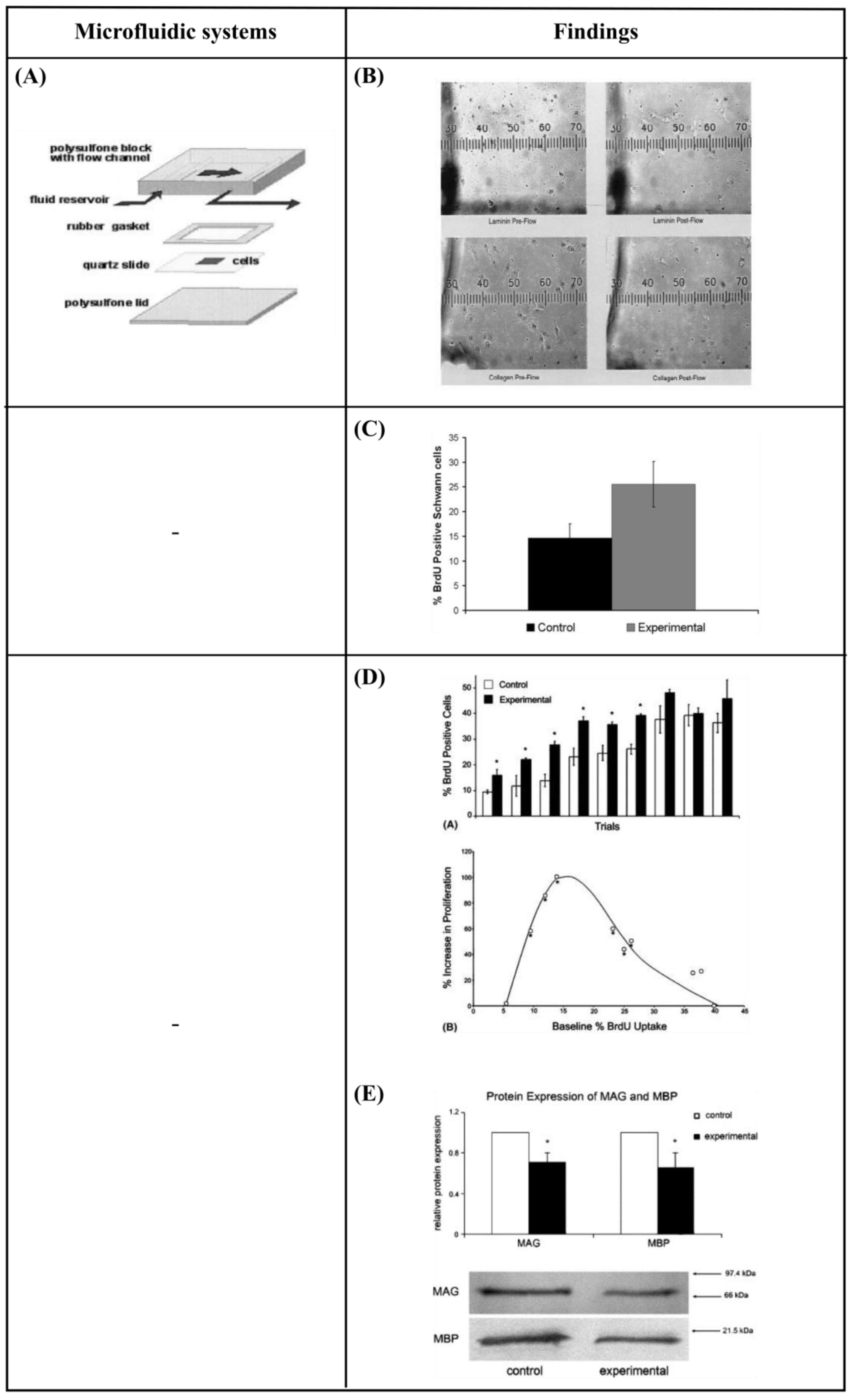
- Chafik, D.; Bear, D.; Bui, P.; Patel, A.; Jones, N.F.; Kim, B.T.; Hung, C.T.; Gupta, R. Optimization of Schwann Cell Adhesion in Response to Shear Stress in an in vitro Model for Peripheral Nerve Tissue Engineering. Tissue Eng. 2003, 9, 233–241. [Google Scholar] [CrossRef]
- Karimi, M.; Bahrami, S.; Mirshekari, H.; Basri, S.M.M.; Nik, A.B.; Aref, A.R.; Akbari, M.; Hamblin, M.R. Microfluidic systems for stem cell-based neural tissue engineering. Lab Chip 2016, 16, 2551–2571. [Google Scholar] [CrossRef] [Green Version]
- Kim, L.; Toh, Y.-C.; Voldman, J.; Yu, H. A practical guide to microfluidic perfusion culture of adherent mammalian cells. Lab Chip 2007, 7, 681–694. [Google Scholar] [CrossRef]
- Young, E.W.K.; Beebe, D.J. Fundamentals of microfluidic cell culture in controlled microenvironments. Chem. Soc. Rev. 2010, 39, 1036–1048. [Google Scholar] [CrossRef] [PubMed]
- Zhang, C.; van Noort, D. Cells in Microfluidics. Top. Curr. Chem. 2011, 304, 295–321. [Google Scholar] [CrossRef] [PubMed]
- Mehling, M.; Tay, S. Microfluidic cell culture. Curr. Opin. Biotechnol. 2014, 25, 95–102. [Google Scholar] [CrossRef] [PubMed]
- Coluccio, M.L.; Perozziello, G.; Malara, N.; Parrotta, E.; Zhang, P.; Gentile, F.; Limongi, T.; Raj, P.M.; Cuda, G.; Candeloro, P.; et al. Microfluidic platforms for cell cultures and investigations. Microelectron. Eng. 2019, 208, 14–28. [Google Scholar] [CrossRef]
- Iakovlev, A.P.; Erofeev, A.S.; Gorelkin, P.V. Novel Pumping Methods for Microfluidic Devices: A Comprehensive Review. Biosensors 2022, 12, 956. [Google Scholar] [CrossRef] [PubMed]
- Pedrosa, S.S.; Caseiro, A.R.; Santos, J.D.; Maurício, A.C. Scaffolds for Peripheral Nerve Regeneration, the Importance of In Vitro and In Vivo Studies for the Development of Cell-Based Therapies and Biomaterials: State of the Art. In Scaffolds in Tissue Engineering—Materials, Technologies and Clinical Applications; InTech: Rijeka, Croatia, 2017. [Google Scholar]
- Papadimitriou, L.; Manganas, P.; Ranella, A.; Stratakis, E. Biofabrication for neural tissue engineering applications. Mater. Today Bio 2020, 6, 100043. [Google Scholar] [CrossRef]
- FitzGerald, J.; Fawcett, J. Repair in the central nervous system. J. Bone Jt. Surg. 2007, 89-B, 1413–1420. [Google Scholar] [CrossRef] [Green Version]
- Ratner, B.D.; Hoffman, A.S.; Schoen, F.J.; Lemons, J.E. Biomaterials Science: An Introduction to Materials in Medicine; Elsevier: Amsterdam, The Netherlands, 2004; ISBN 0125824637. [Google Scholar]
- Gutmann, E.; Guttmann, L.; Medawar, P.B.; Young, J.Z. The Rate of Regeneration of Nerve. J. Exp. Biol. 1942, 19, 14–44. [Google Scholar] [CrossRef]
- Seidlits, S.K.; Lee, J.Y.; E Schmidt, C. Nanostructured scaffolds for neural applications. Nanomedicine 2008, 3, 183–199. [Google Scholar] [CrossRef]
- Dalby, M.J.; Gadegaard, N.; Riehle, M.O.; Wilkinson, C.D.; Curtis, A.S. Investigating filopodia sensing using arrays of defined nano-pits down to 35 nm diameter in size. Int. J. Biochem. Cell Biol. 2004, 36, 2005–2015. [Google Scholar] [CrossRef]
- Flemming, R.G.; Murphy, C.J.; Abrams, G.A.; Goodman, S.L.; Nealey, P.F. Effects of synthetic micro- and nano-structured surfaces on cell behavior. Biomaterials 1999, 20, 573–588. [Google Scholar] [CrossRef] [PubMed]
- Abrams, G.A.; Goodman, S.L.; Nealey, P.F.; Franco, M.; Murphy, C.J. Nanoscale topography of the basement membrane underlying the corneal epithelium of the rhesus macaque. Cell Tissue Res. 2000, 299, 39–46. [Google Scholar] [CrossRef] [PubMed]
- Pasapera, A.M.; Schneider, I.C.; Rericha, E.; Schlaepfer, D.D.; Waterman, C.M. Myosin II activity regulates vinculin recruitment to focal adhesions through FAK-mediated paxillin phosphorylation. J. Cell Biol. 2010, 188, 877–890. [Google Scholar] [CrossRef]
- Crowder, S.W.; Leonardo, V.; Whittaker, T.; Papathanasiou, P.; Stevens, M.M. Material cues as potent regulators of epigenetics and stem cell function. Cell Stem Cell 2016, 18, 39–52. [Google Scholar] [CrossRef] [Green Version]
- Dalby, M.J.; Gadegaard, N.; Oreffo, R.O.C. Harnessing nanotopography and integrin–matrix interactions to influence stem cell fate. Nat. Mater. 2014, 13, 558–569. [Google Scholar] [CrossRef] [PubMed]
- Stukel, J.M.; Willits, R.K. Mechanotransduction of Neural Cells Through Cell–Substrate Interactions. Tissue Eng. Part B Rev. 2016, 22, 173–182. [Google Scholar] [CrossRef] [PubMed] [Green Version]
- Yiannakou, C.; Simitzi, C.; Manousaki, A.; Fotakis, C.; Ranella, A.; Stratakis, E. Cell patterning via laser micro/nano structured silicon surfaces. Biofabrication 2017, 9, 025024. [Google Scholar] [CrossRef]
- Wang, X.; Ohlin, C.A.; Lu, Q.; Hu, J. Cell directional migration and oriented division on three-dimensional laser-induced periodic surface structures on polystyrene. Biomaterials 2008, 29, 2049–2059. [Google Scholar] [CrossRef]
- Rebollar, E.; Frischauf, I.; Olbrich, M.; Peterbauer, T.; Hering, S.; Preiner, J.; Hinterdorfer, P.; Romanin, C.; Heitz, J. Proliferation of aligned mammalian cells on laser-nanostructured polystyrene. Biomaterials 2008, 29, 1796–1806. [Google Scholar] [CrossRef]
- Ranella, A.; Barberoglou, M.; Bakogianni, S.; Fotakis, C.; Stratakis, E. Tuning cell adhesion by controlling the roughness and wettability of 3D micro/nano silicon structures. Acta Biomater. 2010, 6, 2711–2720. [Google Scholar] [CrossRef]
- Orgovan, N.; Peter, B.; Bősze, S.; Ramsden, J.J.; Szabó, B.; Horvath, R. Dependence of cancer cell adhesion kinetics on integrin ligand surface density measured by a high-throughput label-free resonant waveguide grating biosensor. Sci. Rep. 2014, 4, 4034. [Google Scholar] [CrossRef] [PubMed] [Green Version]
- Makarona, E.; Peter, B.; Szekacs, I.; Tsamis, C.; Horvath, R. ZnO Nanostructure Templates as a Cost-Efficient Mass-Producible Route for the Development of Cellular Networks. Materials 2016, 9, 256. [Google Scholar] [CrossRef] [PubMed] [Green Version]
- Babaliari, E.; Kavatzikidou, P.; Angelaki, D.; Chaniotaki, L.; Manousaki, A.; Siakouli-Galanopoulou, A.; Ranella, A.; Stratakis, E. Engineering Cell Adhesion and Orientation via Ultrafast Laser Fabricated Microstructured Substrates. Int. J. Mol. Sci. 2018, 19, 2053. [Google Scholar] [CrossRef] [Green Version]
- Angelaki, D.; Kavatzikidou, P.; Fotakis, C.; Stratakis, E.; Ranella, A. Laser-induced topographies enable the spatial patterning of co-cultured peripheral nervous system cells. Mater. Sci. Eng. C 2020, 115, 111144. [Google Scholar] [CrossRef]
- Rakic, P. Neuron-glia relationship during granule cell migration in developing cerebellar cortex. A Golgi and electonmicroscopic study in Macacus rhesus. J. Comp. Neurol. 1971, 141, 283–312. [Google Scholar] [CrossRef] [PubMed]
- Wilkinson, C.; Riehle, M.; Wood, M.; Gallagher, J.; Curtis, A. The use of materials patterned on a nano- and micro-metric scale in cellular engineering. Mater. Sci. Eng. C 2002, 19, 263–269. [Google Scholar] [CrossRef]
- Simitzi, C.; Karali, K.; Ranella, A.; Stratakis, E. Controlling the Outgrowth and Functions of Neural Stem Cells: The Effect of Surface Topography. ChemPhysChem 2018, 19, 1143–1163. [Google Scholar] [CrossRef] [PubMed] [Green Version]
- Simitzi, C.; Ranella, A.; Stratakis, E. Controlling the morphology and outgrowth of nerve and neuroglial cells: The effect of surface topography. Acta Biomater. 2017, 51, 21–52. [Google Scholar] [CrossRef] [Green Version]
- Manganas, P.; Kavatzikidou, P.; Kordas, A.; Babaliari, E.; Stratakis, E.; Ranella, A. The role of mechanobiology on the Schwann cell response: A tissue engineering perspective. Front. Cell Neurosci. 2022, 16, 948454. [Google Scholar] [CrossRef]
- Chen, W.; Shao, Y.; Li, X.; Zhao, G.; Fu, J. Nanotopographical surfaces for stem cell fate control: Engineering mechanobiology from the bottom. Nano Today 2014, 9, 759–784. [Google Scholar] [CrossRef] [Green Version]
- Reis, R.L. Encyclopedia of Tissue Engineering and Regenerative Medicine; Elsevier: Amsterdam, The Netherlands, 2019; Volume 3, ISBN 978-0-12-813700-0. [Google Scholar]
- Janaszak, M.M.; Wolfe, R.P.; Ahsan, T. Biomechanics in Stem Cell Manufacturing. In Stem Cell Manufacturing; Elsevier Inc.: Amsterdam, The Netherlands, 2016; pp. 27–42. ISBN 9780444632654. [Google Scholar]
- Brown, T.D. Techniques for mechanical stimulation of cells in vitro: A review. J. Biomech. 2000, 33, 3–14. [Google Scholar] [CrossRef] [PubMed]
- Shemesh, J.; Jalilian, I.; Shi, A.; Yeoh, G.H.; Tate, M.L.K.; Warkiani, M.E. Flow-induced stress on adherent cells in microfluidic devices. Lab Chip 2015, 15, 4114–4127. [Google Scholar] [CrossRef] [PubMed]
- Frangos, J.A.; McIntire, L.V.; Eskin, S.G. Shear stress induced stimulation of mammalian cell metabolism. Biotechnol. Bioeng. 1988, 32, 1053–1060. [Google Scholar] [CrossRef] [Green Version]
- Sorkin, A.M.; Dee, K.C.; Tate, M.L.K. “Culture shock” from the bone cell’s perspective: Emulating physiological conditions for mechanobiological investigations. Am. J. Physiol. Physiol. 2004, 287, C1527–C1536. [Google Scholar] [CrossRef] [PubMed] [Green Version]
- Babaliari, E.; Petekidis, G.; Chatzinikolaidou, M. A Precisely Flow-Controlled Microfluidic System for Enhanced Pre-Osteoblastic Cell Response for Bone Tissue Engineering. Bioengineering 2018, 5, 66. [Google Scholar] [CrossRef] [PubMed] [Green Version]
- Sato, M.; Nagayama, K.; Kataoka, N.; Sasaki, M.; Hane, K. Local mechanical properties measured by atomic force microscopy for cultured bovine endothelial cells exposed to shear stress. J. Biomech. 2000, 33, 127–135. [Google Scholar] [CrossRef]
- Lee, A.A.; Graham, D.A.; Cruz, S.D.; Ratcliffe, A.; Karlon, W.J. Fluid Shear Stress-Induced Alignment of Cultured Vascular Smooth Muscle Cells. J. Biomech. Eng. 2001, 124, 37–43. [Google Scholar] [CrossRef]
- Hattori, K.; Munehira, Y.; Kobayashi, H.; Satoh, T.; Sugiura, S.; Kanamori, T. Microfluidic perfusion culture chip providing different strengths of shear stress for analysis of vascular endothelial function. J. Biosci. Bioeng. 2014, 118, 327–332. [Google Scholar] [CrossRef]
- Manbachi, A.; Shrivastava, S.; Cioffi, M.; Chung, B.G.; Moretti, M.; Demirci, U.; Yliperttula, M.; Khademhosseini, A. Microcirculation within grooved substrates regulates cell positioning and cell docking inside microfluidic channels. Lab Chip 2008, 8, 747–754. [Google Scholar] [CrossRef] [Green Version]
- Uttayarat, P.; Chen, M.; Li, M.; Allen, F.D.; Composto, R.J.; Lelkes, P.I. Microtopography and flow modulate the direction of endothelial cell migration. Am. J. Physiol. Circ. Physiol. 2008, 294, H1027–H1035. [Google Scholar] [CrossRef] [Green Version]
- Khabiry, M.; Chung, B.G.; Hancock, M.J.; Soundararajan, H.C.; Du, Y.; Cropek, D.; Lee, W.G.; Khademhosseini, A. Cell Docking in Double Grooves in a Microfluidic Channel. Small 2009, 5, 1186–1194. [Google Scholar] [CrossRef] [PubMed] [Green Version]
- Pedersen, J.A.; Lichter, S.; Swartz, M.A. Cells in 3D matrices under interstitial flow: Effects of extracellular matrix alignment on cell shear stress and drag forces. J. Biomech. 2010, 43, 900–905. [Google Scholar] [CrossRef] [PubMed]
- Choquet, D.; Felsenfeld, D.P.; Sheetz, M.P. Extracellular Matrix Rigidity Causes Strengthening of Integrin–Cytoskeleton Linkages. Cell 1997, 88, 39–48. [Google Scholar] [CrossRef] [PubMed] [Green Version]
- Lee, C.H.; Shin, H.J.; Cho, I.H.; Kang, Y.-M.; Kim, I.A.; Park, K.-D.; Shin, J.-W. Nanofiber alignment and direction of mechanical strain affect the ECM production of human ACL fibroblast. Biomaterials 2005, 26, 1261–1270. [Google Scholar] [CrossRef]
- Hui, E.E.; Bhatia, S.N. Micromechanical control of cell–cell interactions. Proc. Natl. Acad. Sci. USA 2007, 104, 5722–5726. [Google Scholar] [CrossRef]
- Harink, B.; Le Gac, S.; Truckenmüller, R.; van Blitterswijk, C.; Habibovic, P. Regeneration-on-a-chip? The perspectives on use of microfluidics in regenerative medicine. Lab Chip 2013, 13, 3512–3528. [Google Scholar] [CrossRef] [Green Version]
- van der Meer, A.D.; Orlova, V.V.; Dijke, P.T.; Berg, A.v.D.; Mummery, C.L. Three-dimensional co-cultures of human endothelial cells and embryonic stem cell-derived pericytes inside a microfluidic device. Lab Chip 2013, 13, 3562–3568. [Google Scholar] [CrossRef]
- Cimetta, E.; Sirabella, D.; Yeager, K.; Davidson, K.; Simon, J.; Moon, R.T.; Vunjak-Novakovic, G. Microfluidic bioreactor for dynamic regulation of early mesodermal commitment in human pluripotent stem cells. Lab Chip 2012, 13, 355–364. [Google Scholar] [CrossRef] [Green Version]
- Macown, R.J.; Veraitch, F.S.; Szita, N. Robust, microfabricated culture devices with improved control over the soluble microenvironment for the culture of embryonic stem cells. Biotechnol. J. 2014, 9, 805–813. [Google Scholar] [CrossRef] [Green Version]
- Occhetta, P.; Centola, M.; Tonnarelli, B.; Redaelli, A.; Martin, I.; Rasponi, M. High-Throughput Microfluidic Platform for 3D Cultures of Mesenchymal Stem Cells, Towards Engineering Developmental Processes. Sci. Rep. 2015, 5, 10288. [Google Scholar] [CrossRef] [Green Version]
- Yang, K.; Han, S.; Shin, Y.; Ko, E.; Kim, J.; Park, K.I.; Chung, S.; Cho, S.-W. A microfluidic array for quantitative analysis of human neural stem cell self-renewal and differentiation in three-dimensional hypoxic microenvironment. Biomaterials 2013, 34, 6607–6614. [Google Scholar] [CrossRef] [PubMed]
- Krausz, E.; de Hoogt, R.; Gustin, E.; Cornelissen, F.; Grand-Perret, T.; Janssen, L.; Vloemans, N.; Wuyts, D.; Frans, S.; Axel, A.; et al. Translation of a Tumor Microenvironment Mimicking 3D Tumor Growth Co-culture Assay Platform to High-Content Screening. SLAS Discov. Adv. Sci. Drug Discov. 2013, 18, 54–66. [Google Scholar] [CrossRef] [Green Version]
- Lovitt, C.J.; Shelper, T.B.; Avery, V.M. Advanced Cell Culture Techniques for Cancer Drug Discovery. Biology 2014, 3, 345–367. [Google Scholar] [CrossRef] [PubMed] [Green Version]
- Hubert, C.G.; Rivera, M.; Spangler, L.C.; Wu, Q.; Mack, S.C.; Prager, B.C.; Couce, M.; McLendon, R.E.; Sloan, A.E.; Rich, J.N. A Three-Dimensional Organoid Culture System Derived from Human Glioblastomas Recapitulates the Hypoxic Gradients and Cancer Stem Cell Heterogeneity of Tumors Found In Vivo. Cancer Res. 2016, 76, 2465–2477. [Google Scholar] [CrossRef] [PubMed] [Green Version]
- Leclerc, E.; David, B.; Griscom, L.; Lepioufle, B.; Fujii, T.; Layrolle, P.; Legallaisa, C. Study of osteoblastic cells in a microfluidic environment. Biomaterials 2006, 27, 586–595. [Google Scholar] [CrossRef]
- Gomes, M.E.; Sikavitsas, V.I.; Behravesh, E.; Reis, R.L.; Mikos, A.G. Effect of flow perfusion on the osteogenic differentiation of bone marrow stromal cells cultured on starch-based three-dimensional scaffolds. J. Biomed. Mater. Res. 2003, 67, 87–95. [Google Scholar] [CrossRef] [PubMed] [Green Version]
- Dai, C.; Liu, X.; Tang, R.; He, J.; Arai, T. A Review on Microfluidic Platforms Applied to Nerve Regeneration. Appl. Sci. 2022, 12, 3534. [Google Scholar] [CrossRef]
- Hesari, Z.; Mottaghitalab, F.; Shafiee, A.; Soleymani, M.; Dinarvand, R.; Atyabi, F. Application of microfluidic systems for neural differentiation of cells. Precis. Nanomed. 2019, 2, 370–381. [Google Scholar] [CrossRef] [Green Version]
- Ono, T.; Suzuki, Y.; Kato, Y.; Fujita, R.; Araki, T.; Yamashita, T.; Kato, H.; Torii, R.; Sato, N. A Single-Cell and Feeder-Free Culture System for Monkey Embryonic Stem Cells. PLoS ONE 2014, 9, e88346. [Google Scholar] [CrossRef]
- Lo, S.-J.; Yao, D.-J. Get to Understand More from Single-Cells: Current Studies of Microfluidic-Based Techniques for Single-Cell Analysis. Int. J. Mol. Sci. 2015, 16, 16763–16777. [Google Scholar] [CrossRef] [Green Version]
- Wang, B.L.; Ghaderi, A.; Zhou, H.; Agresti, J.J.; Weitz, D.A.; Fink, G.R.; Stephanopoulos, G. Microfluidic high-throughput culturing of single cells for selection based on extracellular metabolite production or consumption. Nat. Biotechnol. 2014, 32, 473–478. [Google Scholar] [CrossRef] [PubMed]
- Perozziello, G.; Candeloro, P.; Gentile, F.; Nicastri, A.; Perri, A.; Coluccio, M.L.; Adamo, A.; Pardeo, F.; Catalano, R.; Parrotta, E.; et al. Microfluidics & nanotechnology: Towards fully integrated analytical devices for the detection of cancer biomarkers. RSC Adv. 2014, 4, 55590–55598. [Google Scholar] [CrossRef]
- Simone, G.; Malara, N.; Trunzo, V.; Renne, M.; Perozziello, G.; Di Fabrizio, E.; Manz, A. Galectin-3 coats the membrane of breast cells and makes a signature of tumours. Mol. Biosyst. 2013, 10, 258–265. [Google Scholar] [CrossRef]
- Simone, G.; Malara, N.; Trunzo, V.; Perozziello, G.; Neuzil, P.; Francardi, M.; Roveda, L.; Renne, M.; Prati, U.; Mollace, V.; et al. Protein-Carbohydrate Complex Reveals Circulating Metastatic Cells in a Microfluidic Assay. Small 2013, 9, 2152–2161. [Google Scholar] [CrossRef] [PubMed]
- Weltin, A.; Slotwinski, K.; Kieninger, J.; Moser, I.; Jobst, G.; Wego, M.; Ehret, R.; Urban, G.A. Cell culture monitoring for drug screening and cancer research: A transparent, microfluidic, multi-sensor microsystem. Lab Chip 2013, 14, 138–146. [Google Scholar] [CrossRef] [PubMed]
- Breslin, S.; O’driscoll, L. Three-dimensional cell culture: The missing link in drug discovery. Drug Discov. Today 2013, 18, 240–249. [Google Scholar] [CrossRef]
- Thoma, C.R.; Zimmermann, M.; Agarkova, I.; Kelm, J.M.; Krek, W. 3D cell culture systems modeling tumor growth determinants in cancer target discovery. Adv. Drug Deliv. Rev. 2014, 69–70, 29–41. [Google Scholar] [CrossRef]
- Marsano, A.; Conficconi, C.; Lemme, M.; Occhetta, P.; Gaudiello, E.; Votta, E.; Cerino, G.; Redaelli, A.; Rasponi, M. Beating heart on a chip: A novel microfluidic platform to generate functional 3D cardiac microtissues. Lab Chip 2016, 16, 599–610. [Google Scholar] [CrossRef]
- Nguyen, M.-D.; Tinney, J.P.; Yuan, F.; Roussel, T.J.; El-Baz, A.; Giridharan, G.; Keller, B.B.; Sethu, P. Cardiac Cell Culture Model As a Left Ventricle Mimic for Cardiac Tissue Generation. Anal. Chem. 2013, 85, 8773–8779. [Google Scholar] [CrossRef] [Green Version]
- Rennert, K.; Steinborn, S.; Gröger, M.; Ungerböck, B.; Jank, A.-M.; Ehgartner, J.; Nietzsche, S.; Dinger, J.; Kiehntopf, M.; Funke, H.; et al. A microfluidically perfused three dimensional human liver model. Biomaterials 2015, 71, 119–131. [Google Scholar] [CrossRef]
- Gärtner, C.; Ungerböck, B.; Schulz, I.; Jahn, T.; Mosig, A.; Mayr, T.; Becker, H. Sensor enhanced microfluidic devices for cell based assays and organs on chip. In Smart Biomedical and Physiological Sensor Technology XII; Cullum, B.M., McLamore, E.S., Eds.; SPIE: Bellingham, WA, USA, 2015; Volume 9487, p. 948704. [Google Scholar]
- Blin, A.; Le Goff, A.; Magniez, A.; Poirault-Chassac, S.; Teste, B.; Sicot, G.; Nguyen, K.A.; Hamdi, F.S.; Reyssat, M.; Baruch, D. Microfluidic model of the platelet-generating organ: Beyond bone marrow biomimetics. Sci. Rep. 2016, 6, 21700. [Google Scholar] [CrossRef] [PubMed] [Green Version]
- Wilmer, M.J.; Ng, C.P.; Lanz, H.L.; Vulto, P.; Suter-Dick, L.; Masereeuw, R. Kidney-on-a-Chip Technology for Drug-Induced Nephrotoxicity Screening. Trends Biotechnol. 2015, 34, 156–170. [Google Scholar] [CrossRef] [PubMed]
- Abaci, H.E.; Gledhill, K.; Guo, Z.; Christiano, A.M.; Shuler, M.L. Pumpless microfluidic platform for drug testing on human skin equivalents. Lab Chip 2014, 15, 882–888. [Google Scholar] [CrossRef] [PubMed] [Green Version]
- Maschmeyer, I.; Lorenz, A.K.; Schimek, K.; Hasenberg, T.; Ramme, A.P.; Hübner, J.; Lindner, M.; Drewell, C.; Bauer, S.; Thomas, A.; et al. A four-organ-chip for interconnected long-term co-culture of human intestine, liver, skin and kidney equivalents. Lab Chip 2015, 15, 2688–2699. [Google Scholar] [CrossRef] [PubMed] [Green Version]
- Perestrelo, A.R.; Águas, A.C.P.; Rainer, A.; Forte, G. Microfluidic Organ/Body-on-a-Chip Devices at the Convergence of Biology and Microengineering. Sensors 2015, 15, 31142–31170. [Google Scholar] [CrossRef] [Green Version]
- Schimek, K.; Markhoff, A.; Sonntag, F.; Blechert, M.; Lauster, R.; Marx, U.; Lindner, G. Integrating skin and vasculature in a Multi-Organ-Chip Platform. BMC Proc. 2015, 9, P20. [Google Scholar] [CrossRef]
- Panoskaltsis-Mortari, A. Bioreactor Development for Lung Tissue Engineering. Curr. Transplant. Rep. 2015, 2, 90–97. [Google Scholar] [CrossRef] [Green Version]
- Radisic, M.; Euloth, M.; Yang, L.; Langer, R.; Freed, L.E.; Vunjak-Novakovic, G. High-density seeding of myocyte cells for cardiac tissue engineering. Biotechnol. Bioeng. 2003, 82, 403–414. [Google Scholar] [CrossRef]
- Li, X.; Valadez, A.V.; Zuo, P.; Nie, Z. Microfluidic 3D cell culture: Potential application for tissue-based bioassays. Bioanalysis 2012, 4, 1509–1525. [Google Scholar] [CrossRef] [Green Version]
- Chung, B.G.; Flanagan, L.A.; Rhee, S.W.; Schwartz, P.H.; Lee, A.P.; Monuki, E.S.; Jeon, N.L. Human neural stem cell growth and differentiation in a gradient-generating microfluidic device. Lab Chip 2005, 5, 401–406. [Google Scholar] [CrossRef]
- Kim, J.H.; Sim, J.; Kim, H.-J. Neural Stem Cell Differentiation Using Microfluidic Device-Generated Growth Factor Gradient. Biomol. Ther. 2018, 26, 380–388. [Google Scholar] [CrossRef]
- Nakashima, Y.; Yasuda, T. Cell differentiation guidance using chemical stimulation controlled by a microfluidic device. Sens. Actuators A Phys. 2007, 139, 252–258. [Google Scholar] [CrossRef]
- Futai, N.; Tamura, M.; Ogawa, T.; Tanaka, M. Microfluidic Long-Term Gradient Generator with Axon Separation Prototyped by 185 nm Diffused Light Photolithography of SU-8 Photoresist. Micromachines 2018, 10, 9. [Google Scholar] [CrossRef] [PubMed] [Green Version]
- Park, J.Y.; Kim, S.-K.; Woo, D.-H.; Lee, E.-J.; Kim, J.-H.; Lee, S.-H. Differentiation of Neural Progenitor Cells in a Microfluidic Chip-Generated Cytokine Gradient. STEM CELLS 2009, 27, 2646–2654. [Google Scholar] [CrossRef] [PubMed] [Green Version]
- Bhattacharjee, N.; Folch, A. Large-scale microfluidic gradient arrays reveal axon guidance behaviors in hippocampal neurons. Microsyst. Nanoeng. 2017, 3, 17003. [Google Scholar] [CrossRef] [PubMed] [Green Version]
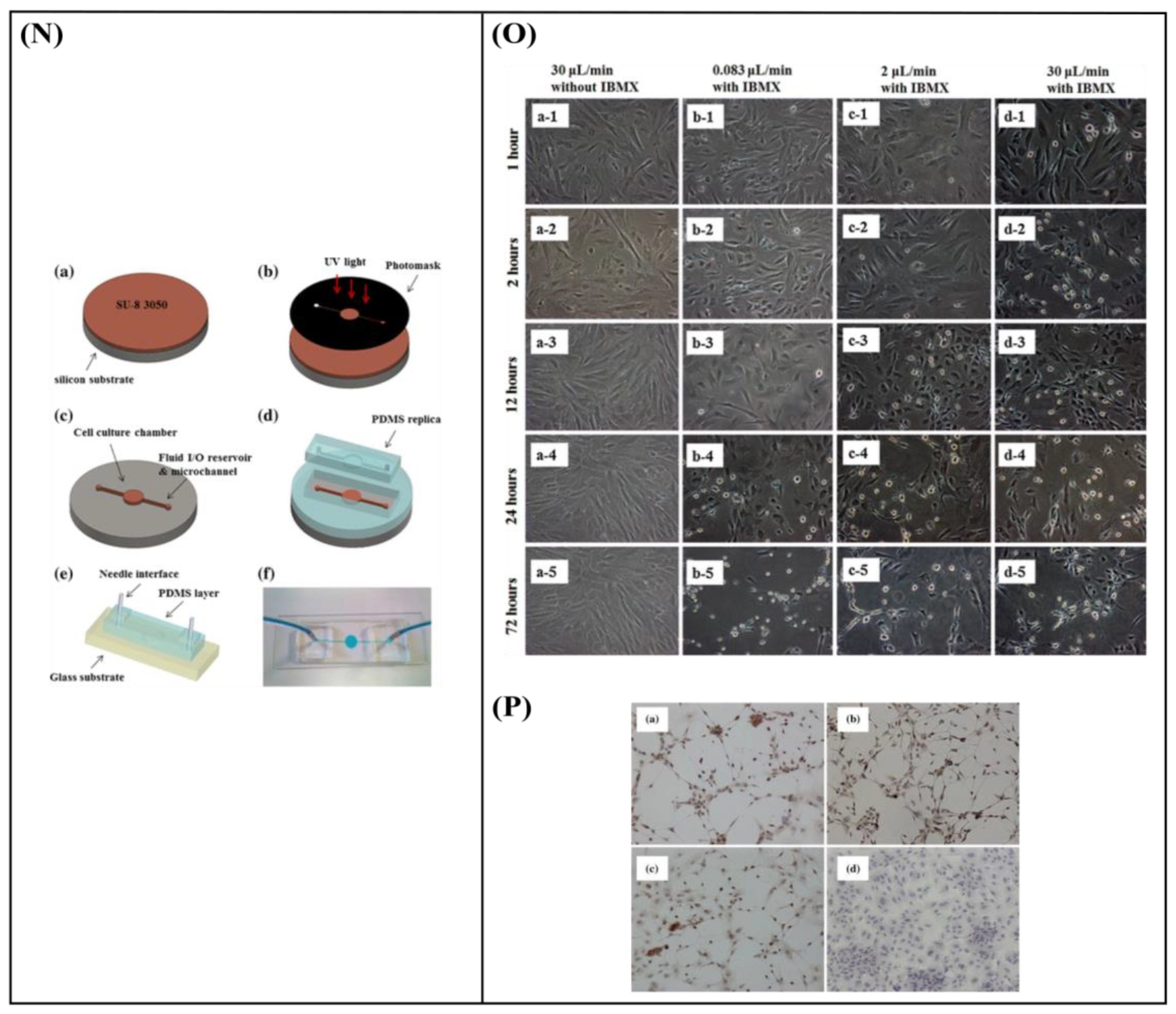
- Cheng, Y.-C.; Tsao, C.-W.; Chiang, M.-Z.; Chung, C.-A.; Chien, C.-C.; Hu, W.-W.; Ruaan, R.-C.; Li, C. Microfluidic platform for human placenta-derived multipotent stem cells culture and applied for enhanced neuronal differentiation. Microfluid. Nanofluidics 2014, 18, 587–598. [Google Scholar] [CrossRef]
- Gupta, R.; Steward, O. Chronic nerve compression induces concurrent apoptosis and proliferation of Schwann cells. J. Comp. Neurol. 2003, 461, 174–186. [Google Scholar] [CrossRef] [PubMed]
- Gupta, R.; Truong, L.; Bear, D.; Chafik, D.; Modafferi, E.; Hung, C.T. Shear stress alters the expression of myelin-associated glycoprotein (MAG) and myelin basic protein (MBP) in Schwann cells. J. Orthop. Res. 2005, 23, 1232–1239. [Google Scholar] [CrossRef]
- Millet, L.J.; Stewart, M.E.; Sweedler, J.V.; Nuzzo, R.G.; Gillette, M.U. Microfluidic devices for culturing primary mammalian neurons at low densities. Lab Chip 2007, 7, 987–994. [Google Scholar] [CrossRef]
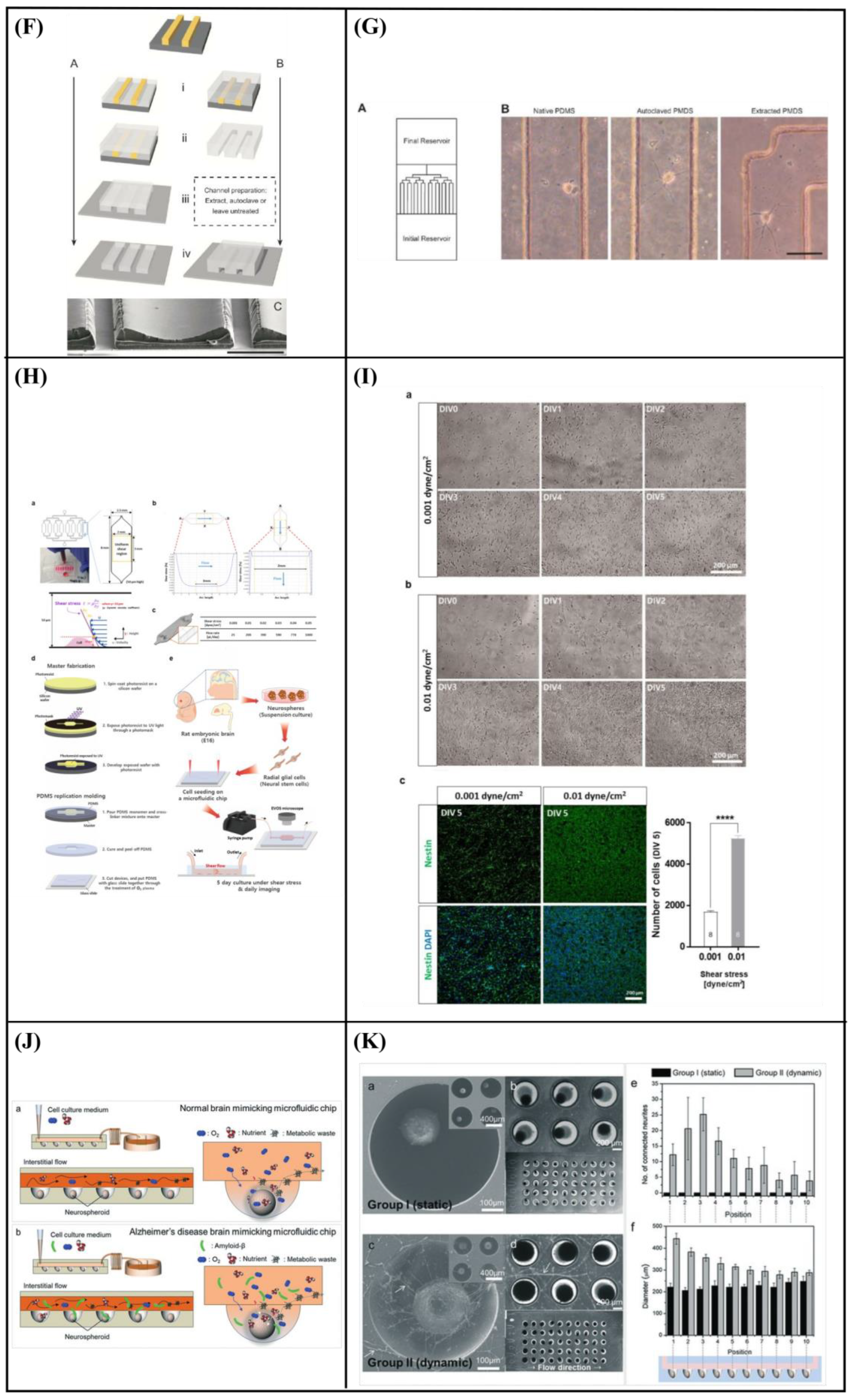
- Park, M.G.; Jang, H.; Lee, S.-H.L.A.C.J.; Lee, C.J. Flow Shear Stress Enhances the Proliferative Potential of Cultured Radial Glial Cells Possibly Via an Activation of Mechanosensitive Calcium Channel. Exp. Neurobiol. 2017, 26, 71–81. [Google Scholar] [CrossRef] [Green Version]
- Park, J.; Lee, B.K.; Jeong, G.S.; Hyun, J.K.; Lee, C.J.; Lee, S.-H. Three-dimensional brain-on-a-chip with an interstitial level of flow and its application as an in vitro model of Alzheimer’s disease. Lab Chip 2014, 15, 141–150. [Google Scholar] [CrossRef]
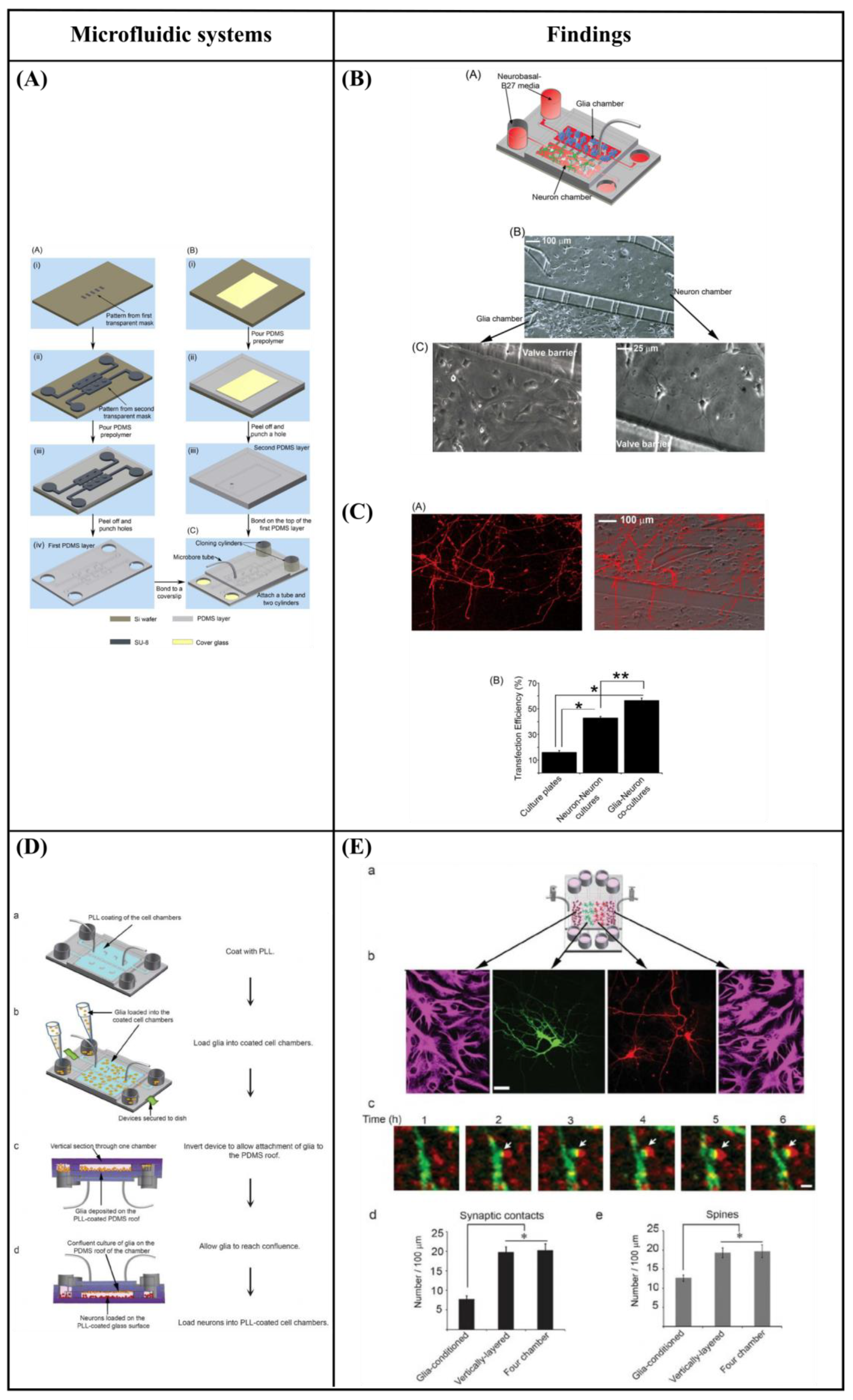
- Majumdar, D.; Gao, Y.; Li, D.; Webb, D.J. Co-culture of neurons and glia in a novel microfluidic platform. J. Neurosci. Methods 2011, 196, 38–44. [Google Scholar] [CrossRef] [PubMed] [Green Version]
- Shi, M.; Majumdar, D.; Gao, Y.; Brewer, B.M.; Goodwin, C.R.; McLean, J.A.; Li, D.; Webb, D.J. Glia co-culture with neurons in microfluidic platforms promotes the formation and stabilization of synaptic contacts. Lab Chip 2013, 13, 3008–3021. [Google Scholar] [CrossRef] [Green Version]
- Robertson, G.; Bushell, T.J.; Zagnoni, M. Chemically induced synaptic activity between mixed primary hippocampal co-cultures in a microfluidic system. Integr. Biol. 2014, 6, 636–644. [Google Scholar] [CrossRef] [PubMed] [Green Version]
- Yang, K.; Park, H.-J.; Han, S.; Lee, J.; Ko, E.; Kim, J.; Lee, J.S.; Yu, J.H.; Song, K.Y.; Cheong, E.; et al. Recapitulation of in vivo-like paracrine signals of human mesenchymal stem cells for functional neuronal differentiation of human neural stem cells in a 3D microfluidic system. Biomaterials 2015, 63, 177–188. [Google Scholar] [CrossRef] [PubMed]
- Park, J.; Koito, H.; Li, J.; Han, A. Microfluidic compartmentalized co-culture platform for CNS axon myelination research. Biomed. Microdevices 2009, 11, 1145–1153. [Google Scholar] [CrossRef] [Green Version]
- Park, J.; Koito, H.; Li, J.; Han, A. Multi-compartment neuron–glia co-culture platform for localized CNS axon–glia interaction study. Lab Chip 2012, 12, 3296–3304. [Google Scholar] [CrossRef]
- Ristola, M.; Sukki, L.; Azevedo, M.M.; Seixas, A.I.; Relvas, J.B.; Narkilahti, S.; Kallio, P. A compartmentalized neuron-oligodendrocyte co-culture device for myelin research: Design, fabrication and functionality testing. J. Micromech. Microeng. 2019, 29, 065009. [Google Scholar] [CrossRef]
- Stratakis, E.; Ranella, A.; Fotakis, C. Biomimetic micro/nanostructured functional surfaces for microfluidic and tissue engineering applications. Biomicrofluidics 2011, 5, 013411. [Google Scholar] [CrossRef] [Green Version]
- Hoffman-Kim, D.; Mitchel, J.A.; Bellamkonda, R.V. Topography, Cell Response, and Nerve Regeneration. Annu. Rev. Biomed. Eng. 2010, 12, 203–231. [Google Scholar] [CrossRef] [Green Version]
- Stevens, M.M.; George, J.H. Exploring and Engineering the Cell Surface Interface. Science 2005, 310, 1135–1138. [Google Scholar] [CrossRef] [PubMed]
- Zhu, M.; Zhou, L.; Li, B.; Dawood, M.; Wan, G.; Lai, C.; Cheng, H.; Leong, K.; Rajagopalan, R.; Too, H.; et al. Creation of nanostructures by interference lithography for modulation of cell behavior. Nanoscale 2011, 3, 2723–2729. [Google Scholar] [CrossRef]
- Mitra, J.; Jain, S.; Sharma, A.; Basu, B. Patterned growth and differentiation of neural cells on polymer derived carbon substrates with micro/nano structures in vitro. Carbon 2013, 65, 140–155. [Google Scholar] [CrossRef]
- Gnavi, S.; Fornasari, B.E.; Tonda-Turo, C.; Laurano, R.; Zanetti, M.; Ciardelli, G.; Geuna, S. The Effect of Electrospun Gelatin Fibers Alignment on Schwann Cell and Axon Behavior and Organization in the Perspective of Artificial Nerve Design. Int. J. Mol. Sci. 2015, 16, 12925–12942. [Google Scholar] [CrossRef] [Green Version]
- Radhakrishnan, J.; Kuppuswamy, A.A.; Sethuraman, S.; Subramanian, A. Topographic Cue from Electrospun Scaffolds Regulate Myelin-Related Gene Expressions in Schwann Cells. J. Biomed. Nanotechnol. 2015, 11, 512–521. [Google Scholar] [CrossRef]
- Kim, Y.-T.; Haftel, V.K.; Kumar, S.; Bellamkonda, R.V. The role of aligned polymer fiber-based constructs in the bridging of long peripheral nerve gaps. Biomaterials 2008, 29, 3117–3127. [Google Scholar] [CrossRef] [PubMed] [Green Version]
- Corey, J.M.; Lin, D.Y.; Mycek, K.B.; Chen, Q.; Samuel, S.; Feldman, E.L.; Martin, D.C. Aligned electrospun nanofibers specify the direction of dorsal root ganglia neurite growth. J. Biomed. Mater. Res. Part A 2007, 83A, 636–645. [Google Scholar] [CrossRef]
- Cao, H.; Marcy, G.; Goh, E.L.K.; Wang, F.; Wang, J.; Chew, S.Y. The Effects of Nanofiber Topography on Astrocyte Behavior and Gene Silencing Efficiency. Macromol. Biosci. 2012, 12, 666–674. [Google Scholar] [CrossRef]
- Mukhatyar, V.J.; Salmerón-Sánchez, M.; Rudra, S.; Mukhopadaya, S.; Barker, T.H.; García, A.J.; Bellamkonda, R.V. Role of fibronectin in topographical guidance of neurite extension on electrospun fibers. Biomaterials 2011, 32, 3958–3968. [Google Scholar] [CrossRef] [Green Version]
- Chew, S.Y.; Mi, R.; Hoke, A.; Leong, K.W. The effect of the alignment of electrospun fibrous scaffolds on Schwann cell maturation. Biomaterials 2008, 29, 653–661. [Google Scholar] [CrossRef] [Green Version]
- Xia, H.; Sun, X.; Liu, D.; Zhou, Y.; Zhong, D. Oriented growth of rat Schwann cells on aligned electrospun poly(methyl methacrylate) nanofibers. J. Neurol. Sci. 2016, 369, 88–95. [Google Scholar] [CrossRef] [PubMed]
- Johansson, F.; Carlberg, P.; Danielsen, N.; Montelius, L.; Kanje, M. Axonal outgrowth on nano-imprinted patterns. Biomaterials 2006, 27, 1251–1258. [Google Scholar] [CrossRef] [PubMed]
- Cecchini, M.; Bumma, G.; Serresi, M.; Beltram, F. PC12 differentiation on biopolymer nanostructures. Nanotechnology 2007, 18, 505103. [Google Scholar] [CrossRef]
- Ferrari, A.; Cecchini, M.; Dhawan, A.; Micera, S.; Tonazzini, I.; Stabile, R.; Pisignano, D.; Beltram, F. Nanotopographic Control of Neuronal Polarity. Nano Lett. 2011, 11, 505–511. [Google Scholar] [CrossRef]
- Gomez, N.; Lu, Y.; Chen, S.; Schmidt, C.E. Immobilized nerve growth factor and microtopography have distinct effects on polarization versus axon elongation in hippocampal cells in culture. Biomaterials 2007, 28, 271–284. [Google Scholar] [CrossRef] [PubMed]
- Goldner, J.S.; Bruder, J.M.; Li, G.; Gazzola, D.; Hoffman-Kim, D. Neurite bridging across micropatterned grooves. Biomaterials 2006, 27, 460–472. [Google Scholar] [CrossRef]
- Hsu, S.-H.; Lu, P.S.; Lai, C.-S.; Chen, C.-J. Oriented Schwann cell growth on microgrooved surfaces. Biotechnol. Bioeng. 2005, 92, 579–588. [Google Scholar] [CrossRef]
- Miller, C.; Jeftinija, S.; Mallapragada, S. Micropatterned Schwann Cell–Seeded Biodegradable Polymer Substrates Significantly Enhance Neurite Alignment and Outgrowth. Tissue Eng. 2001, 7, 705–715. [Google Scholar] [CrossRef] [Green Version]
- Mitchel, J.A.; Hoffman-Kim, D. Cellular Scale Anisotropic Topography Guides Schwann Cell Motility. PLoS ONE 2011, 6, e24316. [Google Scholar] [CrossRef] [Green Version]
- Béduer, A.; Vaysse, L.; Flahaut, E.; Seichepine, F.; Loubinoux, I.; Vieu, C. Multi-scale engineering for neuronal cell growth and differentiation. In Microelectronic Engineering; Elsevier: Amsterdam, The Netherlands, 2011; Volume 88, pp. 1668–1671. [Google Scholar]
- Li, G.; Zhao, X.; Zhang, L.; Yang, J.; Cui, W.; Yang, Y.; Zhang, H. Anisotropic ridge/groove microstructure for regulating morphology and biological function of Schwann cells. Appl. Mater. Today 2019, 18, 100468. [Google Scholar] [CrossRef]
- Zhang, D.; Wu, S.; Feng, J.; Duan, Y.; Xing, D.; Gao, C. Micropatterned biodegradable polyesters clicked with CQAASIKVAV promote cell alignment, directional migration, and neurite outgrowth. Acta Biomater. 2018, 74, 143–155. [Google Scholar] [CrossRef]
- Li, G.; Zhao, X.; Zhao, W.; Zhang, L.; Wang, C.; Jiang, M.; Gu, X.; Yang, Y. Porous chitosan scaffolds with surface micropatterning and inner porosity and their effects on Schwann cells. Biomaterials 2014, 35, 8503–8513. [Google Scholar] [CrossRef]
- Schulte, C.; Rodighiero, S.; Cappelluti, M.A.; Puricelli, L.; Maffioli, E.; Borghi, F.; Negri, A.; Sogne, E.; Galluzzi, M.; Piazzoni, C.; et al. Conversion of nanoscale topographical information of cluster-assembled zirconia surfaces into mechanotransductive events promotes neuronal differentiation. J. Nanobiotechnol. 2016, 14, 18. [Google Scholar] [CrossRef] [Green Version]
- Maffioli, E.; Schulte, C.; Nonnis, S.; Scalvini, F.G.; Piazzoni, C.; Lenardi, C.; Negri, A.; Milani, P.; Tedeschi, G. Proteomic Dissection of Nanotopography-Sensitive Mechanotransductive Signaling Hubs that Foster Neuronal Differentiation in PC12 Cells. Front. Cell. Neurosci. 2018, 11, 417. [Google Scholar] [CrossRef] [Green Version]
- Schulte, C.; Ripamonti, M.; Maffioli, E.; Cappelluti, M.A.; Nonnis, S.; Puricelli, L.; Lamanna, J.; Piazzoni, C.; Podestà, A.; Lenardi, C.; et al. Scale Invariant Disordered Nanotopography Promotes Hippocampal Neuron Development and Maturation with Involvement of Mechanotransductive Pathways. Front. Cell. Neurosci. 2016, 10, 267. [Google Scholar] [CrossRef] [Green Version]
- Terakawa, M. Femtosecond Laser Processing of Biodegradable Polymers. Appl. Sci. 2018, 8, 1123. [Google Scholar] [CrossRef] [Green Version]
- Fadeeva, E.; Deiwick, A.; Chichkov, B.; Schlie-Wolter, S. Impact of laser-structured biomaterial interfaces on guided cell responses. Interface Focus 2014, 4, 20130048. [Google Scholar] [CrossRef]
- Simitzi, C.; Stratakis, E.; Fotakis, C.; Athanassakis, I.; Ranella, A. Microconical silicon structures influence NGF-induced PC12 cell morphology. J. Tissue Eng. Regen. Med. 2013, 9, 424–434. [Google Scholar] [CrossRef] [PubMed]
- Hesari, Z.; Soleimani, M.; Atyabi, F.; Sharifdini, M.; Nadri, S.; Warkiani, M.E.; Zare, M.; Dinarvand, R. A hybrid microfluidic system for regulation of neural differentiation in induced pluripotent stem cells. J. Biomed. Mater. Res. Part A 2016, 104, 1534–1543. [Google Scholar] [CrossRef] [PubMed]
- Jeon, K.J.; Park, S.H.; Shin, J.W.; Kang, Y.G.; Hyun, J.-S.; Oh, M.J.; Kim, S.Y.; Shin, J.-W. Combined effects of flow-induced shear stress and micropatterned surface morphology on neuronal differentiation of human mesenchymal stem cells. J. Biosci. Bioeng. 2014, 117, 242–247. [Google Scholar] [CrossRef]
- Babaliari, E.; Kavatzikidou, P.; Mitraki, A.; Papaharilaou, Y.; Ranella, A.; Stratakis, E. Combined effect of shear stress and laser-patterned topography on Schwann cell outgrowth: Synergistic or antagonistic? Biomater. Sci. 2020, 9, 1334–1344. [Google Scholar] [CrossRef] [PubMed]


| Conventional Static Cultures | Cell Cultures under Microfluidic Flow |
|---|---|
| Non-confined systems | Confined systems |
| No fluid flow | Fluid flow (e.g., laminar, turbulent) |
| Static nutrient and waste products | Consistent nutrient delivery and effective waste removal |
| Large volume of nutrient/reagents | Small volume of nutrient/reagents |
| Limited possibilities for creating mechanical stimulation | Mechanical stimulation possible (e.g., shear) |
| Limited level of spatial control | High level of spatial control |
| Low spatial and temporal control of chemical stimuli | High spatial and temporal control of chemical stimuli |
| Limited possibilities for integration and parallelization | High integration and parallelization |
| Low possibility for in situ read-out of biological processes | Possibility to integrate assays and sensors for in situ read-out of biological processes |
| Simple | Complex experimental set-up |
| Easy to handle | Complex operational control |
| Established culture protocols | Non-standard culture protocols |
| Compatibility with conventional biological assays | Compatibility issues with conventional biological assays |
| Compatibility with established read-out equipment | Compatibility issues with established read-out equipment |
| Gradient Generation—Chemical Stimulation | ||||
|---|---|---|---|---|
| Cell Type | Circulating Flow? | Shear Stress | Findings | Ref. |
| Human neural stem cells (hNSCs) | Yes | 5 × 10⁻⁵ Pa for 4 and 7 days |
| [96] |
| Neural stem cells (NSCs) | Yes | - |
| [97] |
| Adrenal pheochromocytoma (PC12) cells | No | - |
| [98] |
| Primary dorsal root ganglion (DRG) neuronal cells | No | - |
| [99] |
| Human embryonic stem cells (ESCs)-derived neural progenitor cells | Yes | - |
| [100] |
| Primary hippocampal neurons | Yes | Lower than 1.2 × 10⁻³ Pa |
| [101] |
| Placenta-derived multipotent stem cells (PDMCs) | Yes |
|
| [102] |
| Perfusion—Shear stress | ||||
|---|---|---|---|---|
| Cell Type | Circulating Flow? | Shear Stress | Findings | Ref. |
| Schwann cells | Yes | 1.33 Pa for 2 h |
| [9] |
| Schwann cells | Yes | 3.1 Pa for 2 h |
| [103] |
| Schwann cells | Yes | 3.1 Pa for 2 h |
| [104] |
| Primary hippocampal neurons | No | - |
| [105] |
| Radial glial cells (RGCs) | Yes |
|
| [106] |
| Neural progenitor cells | Yes | - |
| [107] |
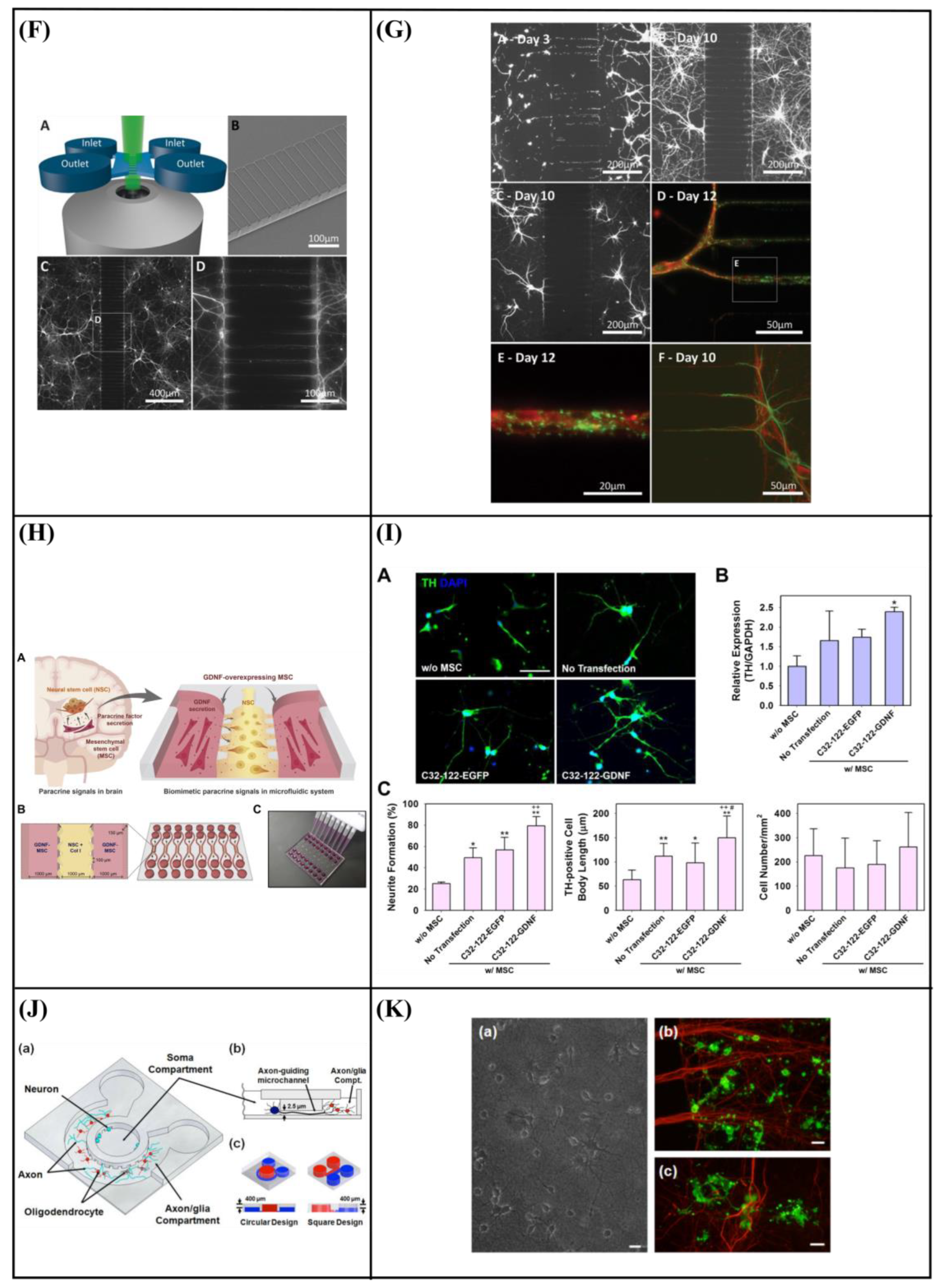
| Co-Culture | ||||
|---|---|---|---|---|
| Cell Type | Circulating Flow? | Shear Stress | Findings | Ref. |
| Co-culture of hippocampal neurons and glia | No | - |
| [108] |
| Co-culture of hippocampal neurons and glia | No | - |
| [109] |
| Primary hippocampal co-culture of neurons and glia | No | - |
| [110] |
| Co-culture of human neural stem cells (hNSCs) with glial cell-derived neurotrophic factor (GDNF)-overexpressing human mesenchymal stem cells (hMSCs) | No | - |
| [111] |
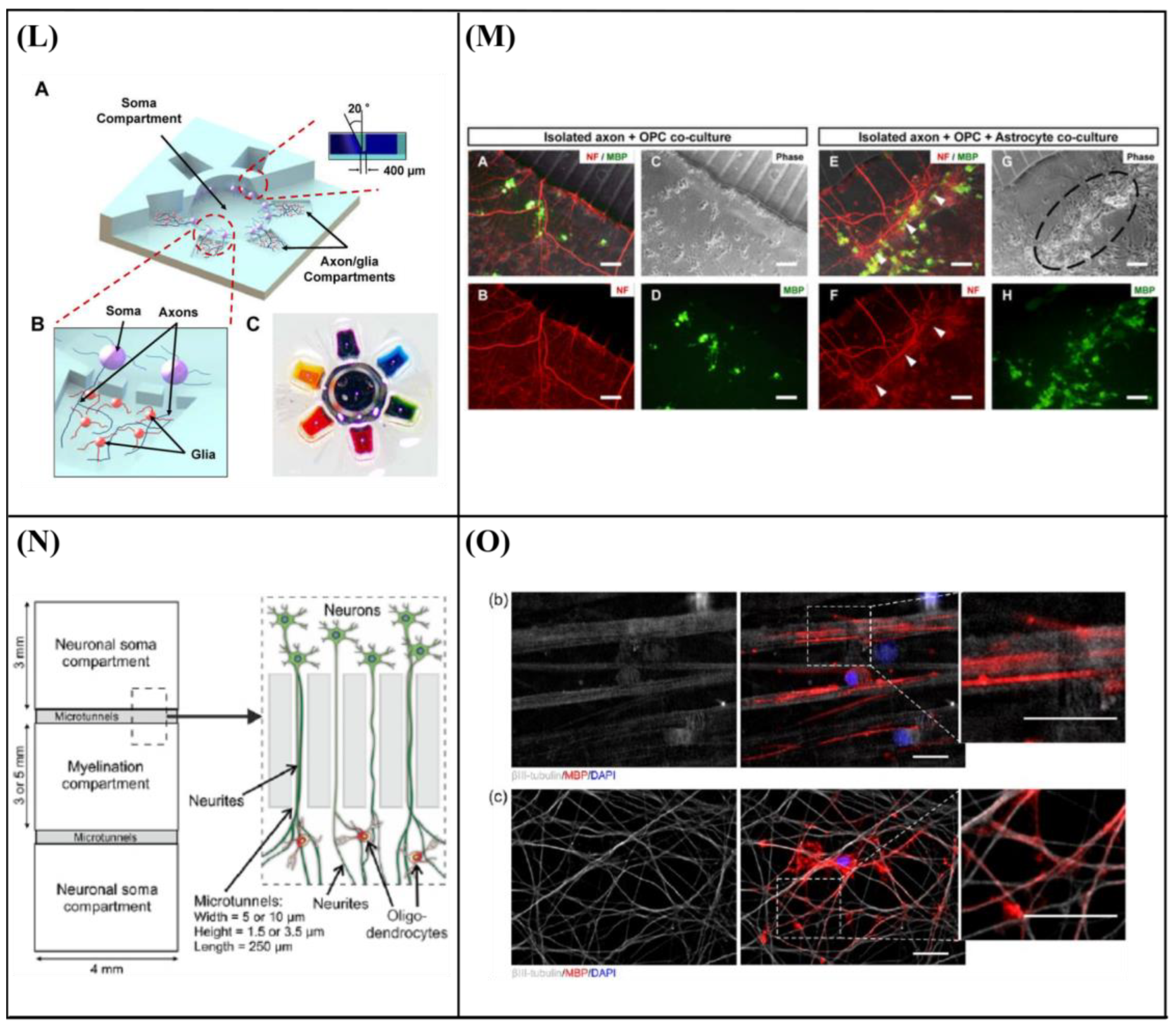
| Co-culture of embryonic central nervous system (CNS) neurons and postnatal oligodendrocytes (OLs) | No | - |
| [112] |
| Co-culture of CNS neuron and glia | No | - |
| [113] |
| Co-culture of rat dorsal root ganglion (DRG) neurons and oligodendrocytes | No | - |
| [114] |
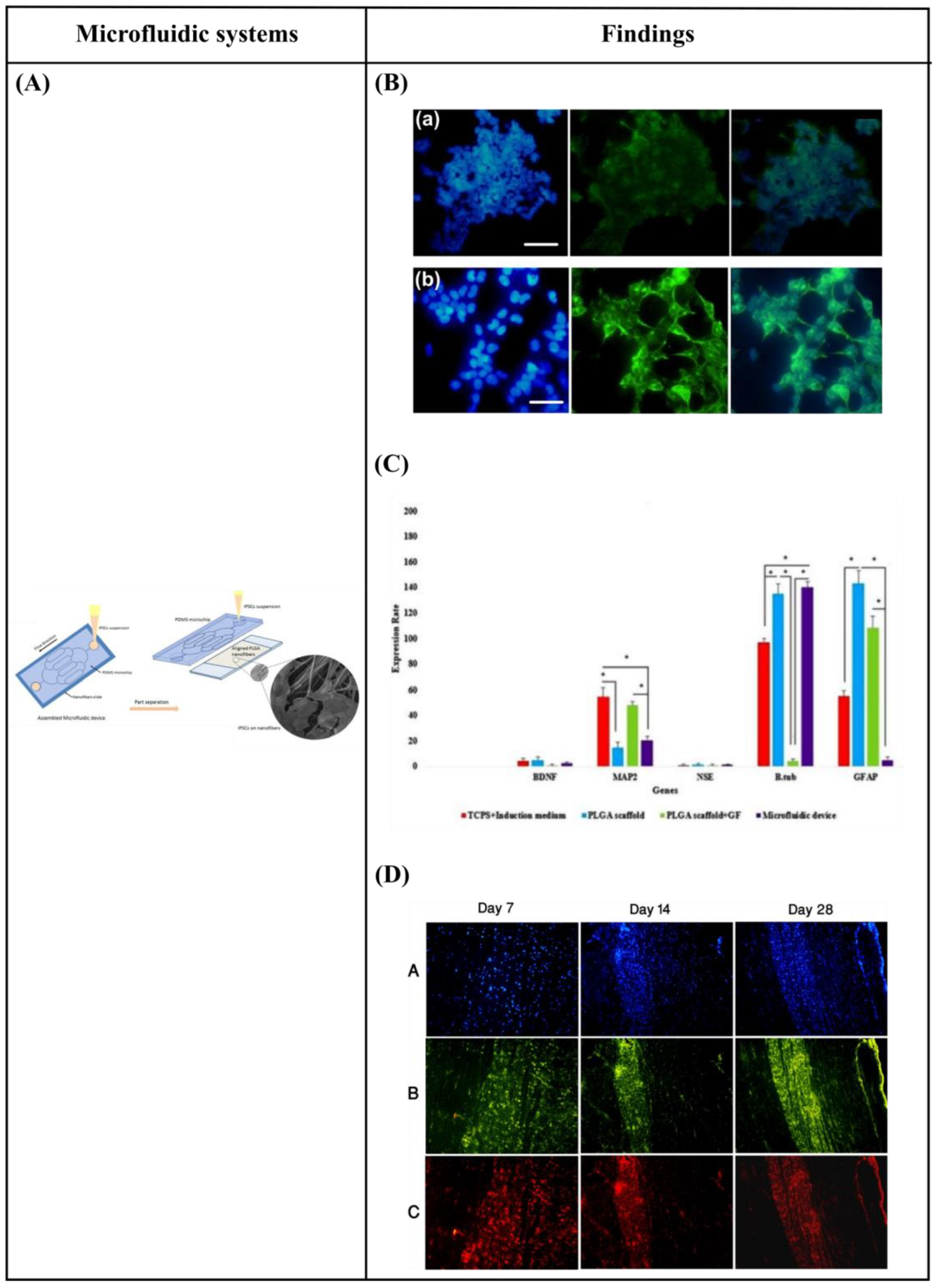
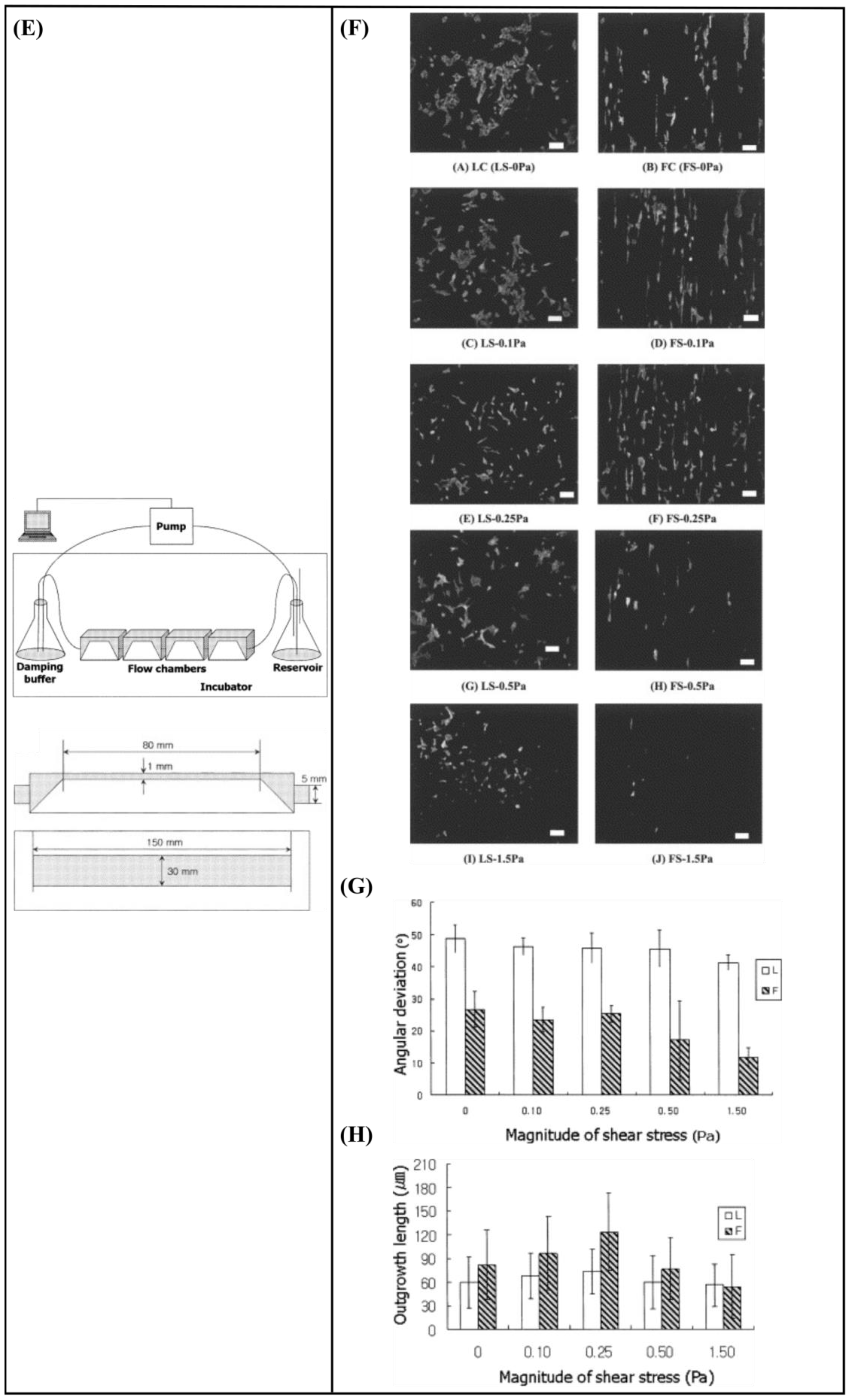
| Substrate | Fabrication Technique | Cell Type | Circulating Flow? | Shear Stress | Findings | Ref. |
|---|---|---|---|---|---|---|
| Poly(lactic-co-glycolic acid) (PLGA) nanofiber-based substrate | Electrospinning | Human induced pluripotent stem cells (hiPSCs) | No | - |
| [146] |
| PLGA microfiber-based substrate | Electrospinning | Adrenal pheochromocytoma (PC12) cells | Yes | 0.1–1.5 Pa for 2 h, 3 times per day for 2 days |
| [1] |
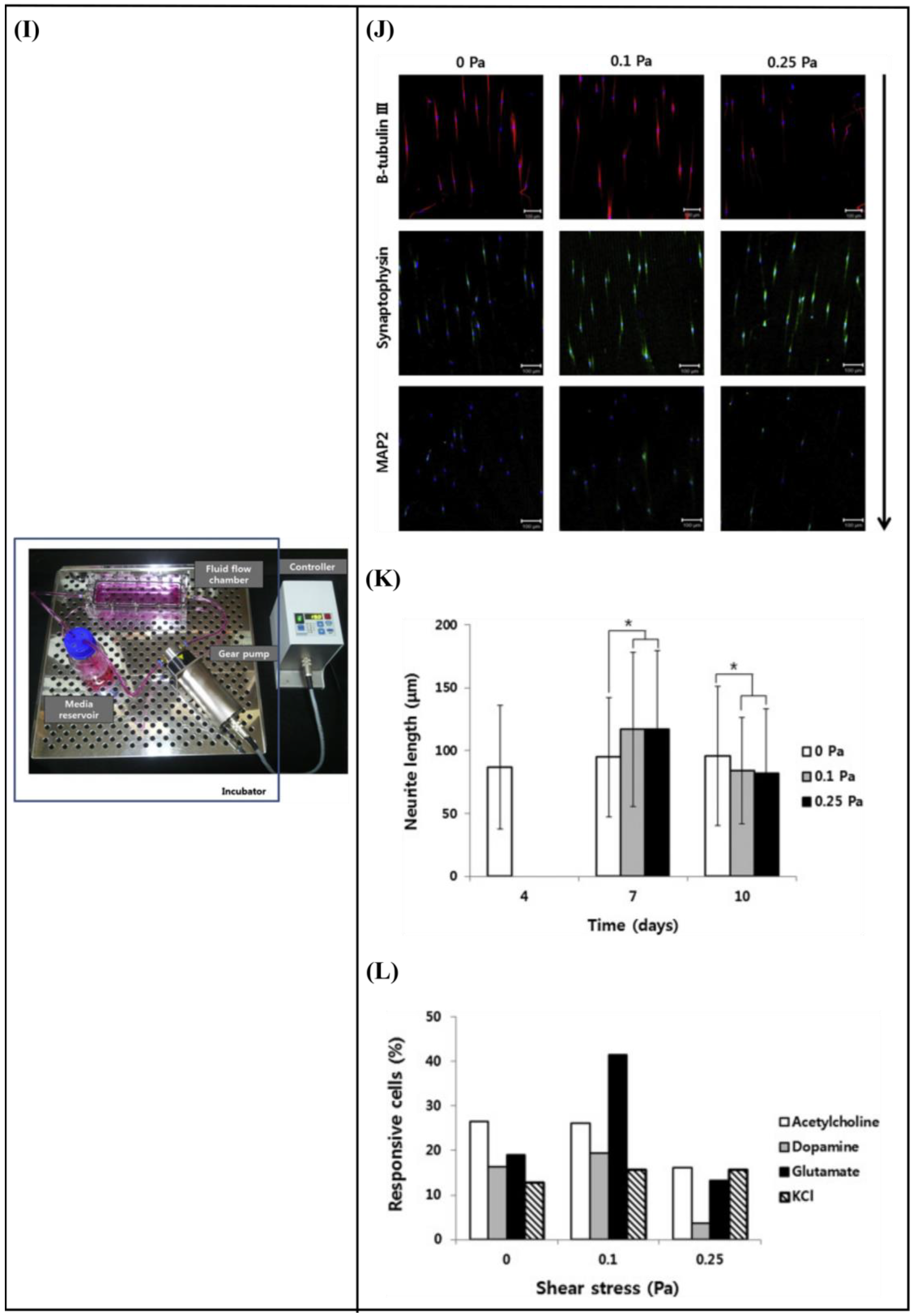
| Polydimethylsiloxane (PDMS) substrate with micrometric grooves | Photolithography | Human mesenchymal stem cells (hMSCs) | Yes | 0.1 and 0.25 Pa for 3 h per day for 2 days |
| [147] |
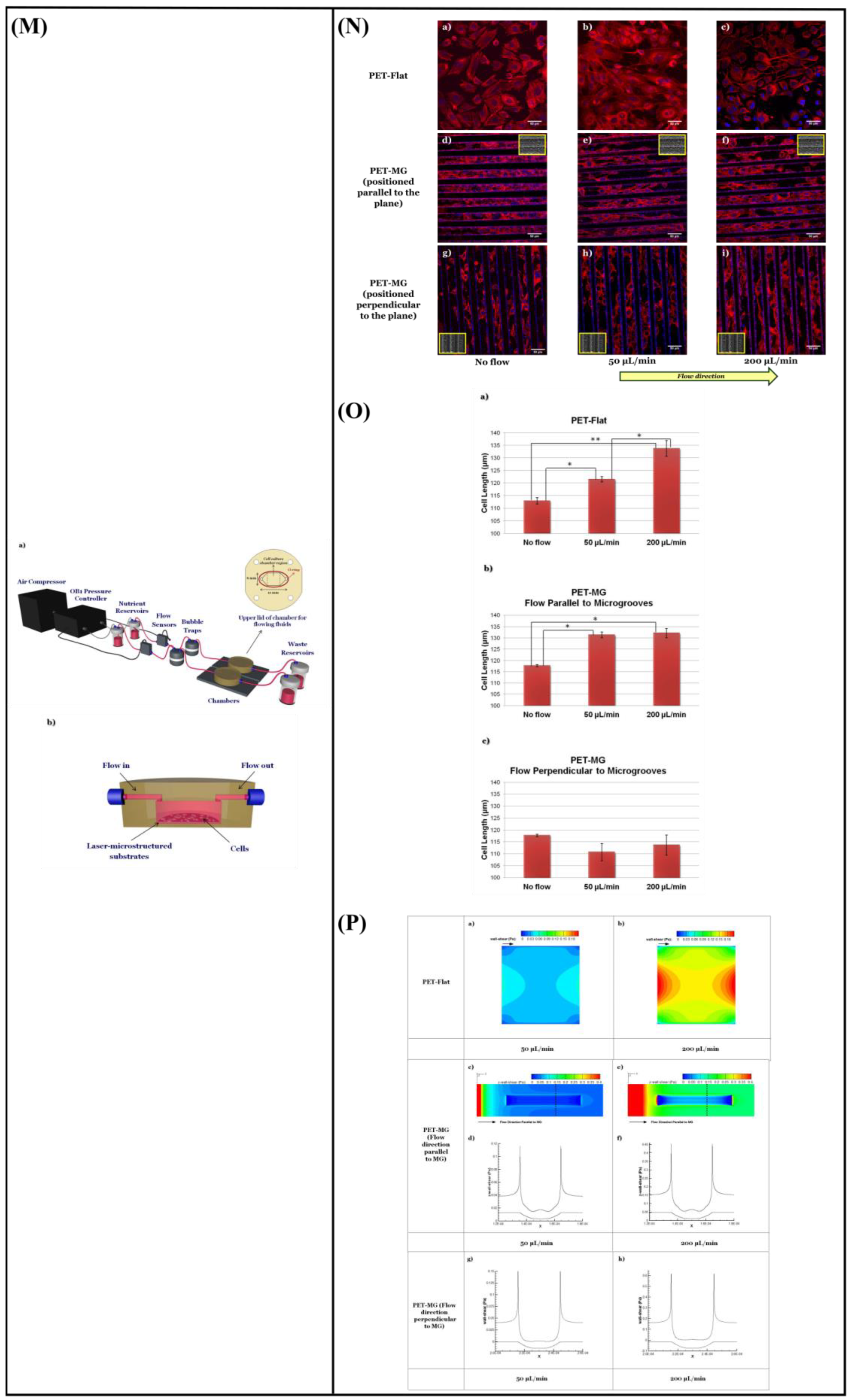
| Polyethylene terephthalate (PET) microgrooved substrate | Ultrafast laser direct writing | Schwann (SW10) cells | Yes | 0.04 and 0.15 Pa, continuous flow for 2 days |
| [148] |
Disclaimer/Publisher’s Note: The statements, opinions and data contained in all publications are solely those of the individual author(s) and contributor(s) and not of MDPI and/or the editor(s). MDPI and/or the editor(s) disclaim responsibility for any injury to people or property resulting from any ideas, methods, instructions or products referred to in the content. |
© 2023 by the authors. Licensee MDPI, Basel, Switzerland. This article is an open access article distributed under the terms and conditions of the Creative Commons Attribution (CC BY) license (https://creativecommons.org/licenses/by/4.0/).
Share and Cite
Babaliari, E.; Ranella, A.; Stratakis, E. Microfluidic Systems for Neural Cell Studies. Bioengineering 2023, 10, 902. https://doi.org/10.3390/bioengineering10080902
Babaliari E, Ranella A, Stratakis E. Microfluidic Systems for Neural Cell Studies. Bioengineering. 2023; 10(8):902. https://doi.org/10.3390/bioengineering10080902
Chicago/Turabian StyleBabaliari, Eleftheria, Anthi Ranella, and Emmanuel Stratakis. 2023. "Microfluidic Systems for Neural Cell Studies" Bioengineering 10, no. 8: 902. https://doi.org/10.3390/bioengineering10080902