Article

Dynamic and Steady-State Simulation Study for the Stabilization of Natural Gas Condensate and CO2 Removal through Heating and Pressure Reduction

1
Department of Chemical Engineering, University of Engineering and Technology, Lahore 54890, Pakistan
2
Process Systems, Technomak Energy International FZC, Sharjah P.O. Box 41980, United Arab Emirates
3
Department of Engineering, Nottingham Trent University, Nottingham NG11 8NS, UK
4
Process Design, AIN Engineering Services, Lahore 54800, Pakistan
*
Author to whom correspondence should be addressed.
ChemEngineering 2023, 7(5), 78; https://doi.org/10.3390/chemengineering7050078
Submission received: 15 June 2023 / Revised: 2 August 2023 / Accepted: 15 August 2023 / Published: 29 August 2023
(This article belongs to the Collection Green and Environmentally Sustainable Chemical Processes)

Abstract

:
Stabilization of condensate is a highly energy-consuming process compared to other oil and gas processes. There is a need to reduce this energy consumption. Therefore, the present work aims to simulate the stabilization unit in terms of available energy and on-spec stabilized condensate products. Natural gas condensate liquids (NGL) need to be stabilized by eliminating lighter hydrocarbon gases and acid gases before being sent to the refinery. Stabilized NGL has the vapor pressure determined as a Reid vapor pressure of 7 psia, showing that light components did not evolve as a separate gas phase. Stabilization and CO2 removal was performed through the distillation method by heating and pressure reduction using steady state and dynamic simulation through Aspen HYSYS. Different process alterations around the exchanger and column have been studied based on the utilities available for the stabilization and CO2 removal process. Sensitivity studies, including the impact of CO2 concentration, the temperature at the inlet of the stabilizer flash separator, and the dynamic simulation for the PID controller, have been performed to analyze the impact on the process parameters, such as Reid vapor pressure (RVP) and CO2 of the rundown air cooler and heat duties of the exchangers. Actual plant data have been used for the validation of process simulation values for the accuracy of the condensate stabilization unit model. Based on the scenarios analyzed, it can be concluded that the nitrogen stripping method achieved 7 ppmv CO2 and 7 psia RVP in the condensate from the cooler outlet, while a variation of 29 bpd was observed for the stabilized condensate flowrate throughout all scenarios with data validation showing 0.24% discrepancy between Aspen Hysys data and actual plant data.

1. Stabilization of Natural Gas Condensate

1.1. Introduction

Increased world demand for crude oil is causing the depletion of oil reserves, which is increasing oil and energy prices. Crude oil, as the main contributor to the world’s power supply, requires processing by oil and gas plants that have the minimum operational cost for producing quality oil products. Further, natural gas condensate liquids (NGL) are medium fractions of crude oil with a carbon chain of C5-C9 [1], which can be converted to different petroleum products, such as gasoline, light oil, and jet fuels. When NGL is extracted from gas, it may contain hydrocarbon gases (C1-C4) with impurities, including CO2, H2S, N2, O2, various salts, and water [2]. However, impurities including H2S and CO2 increase with the decrease in the conventional oil reserves. These impurities must be removed from NGL to produce saleable products for the market [3]. Unstabilized NGL, if not treated for impurities and hydrocarbon gases, will release these gases at low pressure and high temperature, affecting the condensate’s quality and resulting in environmental issues and operational disturbances, including corrosion to pumps and storage tanks [4]. Consequently, the growing concern regarding impurities is an important driver for the development of operations in the petroleum industries, and more energy-efficient and environmentally friendly processes will be required to reduce the processing cost of crude oil. The stabilization method is an important method for industry to remove gaseous impurities from unstabilized NGL. Reid vapor pressure (RVP) is a mean for the measurement of NGL stabilization, and it is the absolute vapor pressure exerted by the vapors of the liquid and any dissolved gases at 37.8 °C (100 °F) [4]. About 6–7 psia RVP (less than 8 psia) is an industrial accepted value for a good stabilization point for NGL [5]. Generally, the required RVP is obtained by removing the lighter hydrocarbon gases through heating and by reducing the pressure. Heating/pressure reduction also removes H2S, CO2, O2, N2, and other gases, along with stabilization of NGL [3]. Generally, the crude oil stabilization process consists of heaters, separators, coolers, and stabilizer columns [6]. As a result, stabilized NGL is sent to a storage tank for transfer to the refinery, while lighter hydrocarbon gases, along with gases impurities, are sent to one of the following sources; (i) the fuel gas is diluted by injecting corrosive gas into the fuel gas header if the downstream piping is designed based on corrosive material; (ii) re-compress the gas to inject it into a high-pressure gas handling system; (iii) recover the fuel gas by removing acidic gases through sweetening, such as using the amine system; (iv) gases can be recycled into a reservoir for enhanced oil recovery purposes; or (v) gases are used to flare as a continuous source of light-up gas with the redundant supply of fuel gas from other sources [7]. Stabilized NGL is then sent to the refinery for mixing with heavy crude oil [8], to help in the pumping of heavy crude oil by reducing viscosity from the storage tanks to the preheat exchanger trains and to increase the production of motor gasoline [9].
So far, many process schemes regarding condensate stabilization have been analyzed to study the said system. The effect of feed conditions, such as on RVP of 8.78 psia, on sulfur content was analyzed and the validation of HYSYS results with actual plant conditions was performed. Pro II software results have been discussed in the literature regarding the fractionation process having a compressor and de-salter [1] and also for flash vaporization [3]. Compression, heat integration (reboiler and column), dynamic controlling, and economic analysis for the fractionation column have also been performed [2]. The effect of feed conditions, including the increase in water content from 2 to 29 bpd to achieve 12 psia TVP, and validation of the Aspen HYSYS results for the stabilization process with actual plant data, have reported a 3% variation [4]. Gases from the top of the fractionation column in the stabilization process are recovered through liquefaction, LPG production, and the compression unit, for which the 219% highest rate of return (ROR) was found for the liquefaction process based on economic analysis [5]. Development of stabilizer column models through the artificial neural networks (ANN) method have shown an average absolute deviation percent (ADD%) of 1.6 for RVP and 3.8 for H2S concentration [6], in comparison to the support vector machine (SVM) method with a squared correlation coefficient of 0.97 for H2S concentration and 0.94 for Reid vapor pressure (RVP) [7]. The pressure effect through model development on the stabilization column with a mean absolute error of 2.69% for process variables has been studied in the literature [10]. Modeling of the stabilizer column in the refinery has also been performed with an error percentage in LPG and gasoline properties, among which a maximum of 6.67% was reported for the specific gravity of LPG [9]. Stabilization along with H2S removal through a split-flow configuration has provided reasonable result validation and an optimal split ratio of 15% based on economic analysis [11]. The pressure selection of multiple separators based on the gas–oil ratio (GOR), with the selection of reduced compressor power for recovery of separator off-gas in the flash vaporization method, have also been discussed [11]. Different techno-commercial studies of desulfurization of condensate have been discussed, such as desulfurization of condensate through caustic wash, oxidative desulfurization via H2SO4, and combined oxidative desulfurization with caustic wash. Among these, oxidative desulfurization is a commercially viable method to decrease the total sulfur content from 8500 ppm to less than 700 ppm by eliminating all hydrogen sulfide with mercaptans and severely reducing other heavy sulfur-containing compounds. [12]. In case of defects in the cooling system at the top stage of debutanizer column, modification of LPG and NGL production has been discussed to avoid flaring by selecting a reflux stream temperature of 55 °C [13]. Fractionation is a selected technology with an optimized parameter for RVP of 10 psia in summer and 12 psia in winter among flash vaporization and fractionation methods [14,15]. Shutdown reduction methods for compressors in the condensate stabilization unit have been analyzed based on first-out alarms, transmitter selection, and a programmable logic controller [16]. Energy and exergy analysis of the stabilizer column with a water draw pan to remove water and a reduction of reboiler duty show a reduction of compressor power with 80% exergy efficiency [15]; also, the addition of a de-ethanizer and debutanizer column to increase the production of LPG in an existing gas plant reduces condensate production and compressor power [17]. Evaluating the effect of operational parameters such as the desalter mixing valve differential pressure, column pressure, condenser temperature, inlet feed column temperature, and the C5+ component’s effect on increasing performance of the condensate fractionation process have been discussed [18,19]. The heat pump recuperation-based condensate fractionation process has been studied to save 73.43% and 83.48% of the condenser and reboiler energy compared to a conventional column [20,21], and a substantial 50% energy saving has been achieved [22]. The development of a concentric internally heat-integrated distillation column has also been discussed [23]. A debottlenecking study was performed for a 20% increase in the throughput of condensate with the installation of an additional heat transfer area of 1554 m2 while keeping the utility consumption maintained at the existing level [22]. A fractionation column with steam stripping and flash vaporization has been discussed to achieve 9 psia RVP [24]. Details of the Soave Redlich Kong (SRK) or Peng–Robinson (PR) equation are used for the condensate stabilization process of non-polar components in the literature [4,10,25].

1.2. Literature Review

Stabilization of condensate can be achieved through either of two methods, namely flash vaporization or fractionation. Flash vaporization is an older technique based on the vapor–liquid equilibrium having different phase densities [1]. It operates at different temperatures and pressures of the condensate liquid to flash into vapor and stabilize the oil [2] and generally consists of a number of separators and heaters. The number of vessels required for the stabilization of oil depends upon the gas-to-oil ratio as well as the wellhead pressure [11]. The flash vaporization method is cheaper than the fractionation method; however, it cannot meet the RVP requirements due to the large loss of lighter hydrocarbons, therefore, a flash separator alone cannot be used for stabilization [7].
Fractionation is an advanced technique using columns, heaters, and vessels to stabilize the oil of various specifications by controlling heat to strip out lighter hydrocarbons and gaseous impurities [14]. The condensate is fed into the flash separator, where the lighter portion is removed (using flash vaporization), while the liquid is preheated in the heat exchanger and sent to the stabilization tower or stripper. Stripping vapor from the reboiler is used to remove the lighter hydrocarbon gases, CO2, and sulfur components to realize that stabilization and de-corrosiveness can be performed in one column.
To analyze the performance of flash vaporization and fractionation techniques, different flow conditions for the stabilization of condensates have been considered in the literature [1,2,3,4], including: (i) inlet feed parameters for the flash separator, including the variation of feed flowrate, temperature, pressure, composition, BS&W, and impurities such as wax, asphaltenes, salts, and metals; (ii) flash separator parameters, such as operating pressure, operating temperature, and carry over of condensate/water to the stabilizer column; (iii) heater performance parameters (duty and pressure drop); (iv) stabilizer column performance parameters, such as column hydraulics, reboiler duty, column bottom specifications, such as water content, RVP, CO2, H2S, and condensate/gas product flowrate; (v) cooler performance parameters (duty, pressure drop, temperature approach and final storage temperature); and (vi) stabilization column flow configuration (straight-through or split-flow). The variation range is usually a 10–30% split-flow ratio with an optimal reported value of 15% [7]. However, the straight method has lower energy consumption and a smaller condensate production rate, while the split-flow scheme has more condensate production by reducing flash gas flow with higher energy requirements. Nevertheless, for large-scale applications, the split-flow configuration for the stabilizer column is more efficient and economical due to the higher production of condensate with the same inlet flowrate to the stabilizer column [4,7,18].
In addition, the above parameters have also been studied on simulators, such as Aspen HYSYS and Pro/II [11], and the results have been compared with operating plant data. It has been found that PRO/II shows a better agreement for the light hydrocarbons with the plant data than HYSYS, while HYSYS shows better agreement for the heavy hydrocarbons than PRO/II due to their proprietary method of simulation for the same Peng–Robinson (PR) equation of state [24]. The PR equation of state has been considered as a property package in simulators for petroleum and gas applications due to the wider range of temperature and pressure values (T > −271 °C and P < 1035 bar) for non-polar and slightly- polar real components in single and multiphase systems. Further, the PR equation of state has a wider binary interaction database for a wide range of temperature and pressure conditions [4,26]. The PR equation of state is widely used in LPG modeling due to its wider application and sound results.
So far, a lot of work has been carried out on condensate fractionation and flash vaporization techniques for stabilization of condensates with the removal of impurities such as water and H2S. Techniques previously studied are steam stripping in a column, split-flow configuration around columns, heat pump configurations around columns, a concentric internally heat integrated column, removal of water through a water draw pan in columns, recovery of the off-gases stream through liquefaction/LPG recovery/compression, and H2S removal from sour condensate through caustic wash (MEROX)/oxidative desulfurization (H2SO4/hydrodesulfurization) [27]. Parametric studies have been studied, such as pressure selection of separators in flash vaporization and pressure effects on the column. Further analysis, such as ANN/SVM modeling of columns, energy/exergy analysis of columns, the impact of inlet process conditions on the condensate stabilization process, debottlenecking/cross pinch exchanger analysis, economic analysis of the system, dynamic controllers’ response studies, modification of process units to obtain LPG/NGLs products, and shutdown reduction methods for compressors in condensate stabilization processes have been performed. Furthermore, HYSYS -simulated result validation with actual plant data/Pro-II software results has also been studied previously.
However, the intention for the removal of a high percentage of CO2 along with NGL stabilization is rarely found in the literature [10,11,12,13,14,15,16]. In the present research work, a maximum 15 mol% CO2 concentration in the feed stream of the stabilizer unit is studied to achieve CO2-free condensate with stabilizer unit parameters of a 7 psia Reid vapor pressure (RVP), however, the maximum CO2 in feed reported in the literature [19] is only 7.47 mol%.
Therefore, the novelty of the present research work for high CO2 in the inlet of the condensate stabilization unit will be: (i) it removes the high composition CO2 (15 mol%) from the raw condensate along with the required specification of 7 psia RVP by utilizing pressure reduction and heat conservation; (ii) validation of the Aspen HYSYS simulated model against the actual plant operating data for CO2 and RVP of stabilized condensate; (iii) nitrogen stripping in the additional stripper column installed at the bottom of the stabilizer reboiler; (iv) dynamic simulation of the condensate stabilization process to analyze plant behavior; and (v) different column pressure operation. Some previously described concepts of straight-through/split-flow schemes [8] are also discussed in this research for a high CO2 scenario.

2. Process Description

Fractionation is considered for stabilizing an NGL condensate of 7 psia RVP with a small quantity of CO2 and other impurities in the plant outlet condition. The process consists of a flash separator, heat exchanger, stabilizer column, hot oil-based reboiler, and an air cooler, as shown in Figure 1.
Initially, the unstabilized feed is introduced from the upstream system/LP well into the flash separator operating at 140 psig and 69 °F, where the primary separation takes place. The flash separator is a three-phase separator that separates gas, oil, and produced water by utilizing the density differences between the phases. The vapor phase is flashed off, the liquid mixture is partially vaporized, and equilibrium is reached between the phases. The produced water is separated and directed to the produce water degasser at 55 psig after the level control valve (LCV). Oil collected from the flash separator is routed for stabilization via a heat exchanger on the tube side, where it is preheated with hot reboiled condensate to 160 °F. The corrosive fuel gas (mainly C1-C4 and some CO2) from the flash separator is routed to the fuel gas system at 105 psig after pressure reduction from the pressure control valve (PCV). Condensate from the heat exchanger after LCV enters the packed-type stabilizer column at 70 psig and 157 °F.
The internal flash section above the 1st stage in the column is added in order to reduce the pressure to the column operating pressure of 55 psig. It is worth noting that the 2nd flash drum inside the column reduces the vapor pressure of condensate and reduces the vapor load of the column. Further, stabilization occurs in the column, which is without reflux and is derived from the reboiler, where heat is supplied to process the fluids at 305 °F through hot oil flowing in the tubes of the exchanger. The heat is adjusted in the reboiler to obtain the bottom product with 7 psia RVP. Light hydrocarbon vapors and acidic gases (C1, C2, C3, C4, CO2, and H2S) are stripped from the stabilizer column, and it is vented to the low-pressure flare system at 25 psig after the PCV. The actual pressure will depend upon the flare system back pressure. The reboiled condensate then flows toward the shell side of the heat exchanger and is cooled down to 220 °F. The condensate temperature is further reduced to 135 °F via an air cooler and then sent for storage in a tank. All schemes are studied under the same feed conditions and composition, which are shown in Table 1 and Table 2. The composition of the feed stream and the feed conditions are obtained from the actual plant, and to have a thorough comparison, they are kept the same in all analyses and model verifications.
In comparison to the above conventional process, the following process schemes have been studied:

2.1. Stabilizer Column Inlet Flow Straight-through and Split-Flow Configuration

The conventional process scheme is a straight-through scheme, which are discussed in Figure 1. However, a split-flow scheme is made by partly or totally bypassing the feed bottom heat exchanger, as shown in Figure 2. The bypass stream of the heat exchanger enters at the 1st stage of the column at separator outlet temperature while the stream from the feed bottom heat exchanger enters at the 3rd stage of the column at 160 °F.

2.2. Stripping Nitrogen in the Additional Column Installed at the Bottom of the Stabilizer Reboiler

The previous conventional condensate stabilization scheme is considered with the addition of stripping nitrogen, which is injected at the bottom of the two-staged new striping column, while the condensate stream from the stabilizer reboiler is added at the top of the new stripping column (Figure 3).

2.3. Same Separator and Column Gas Outlet Pressure for Different Column Pressure Operation

Conventional condensate stabilization scheme is considered with changes of column pressure to get system overall gas outlet pressure from 25 to 105 psig for calculation of CO2 in stabilized condensate at rundown cooler outlet (Figure 4).

3. Methodology

In this research work, various flow configurations of condensate stabilization process have been studied to achieve CO2 removal capacities from un-stabilized sour condensate for overall performance of unit.
Scenario 1 shows straight through (Figure 1) and split flow (Figure 2) configuration around feed bottom heat exchanger to stabilizer column. Straight The straight-through configuration has a 100% flowrate (0% split-flow ratio) passing through the exchanger. A 0–100% flow passes through the exchanger in the split-flow configuration, while the rest bypasses the exchanger. Both configurations are studied at 7 psia RVP at the rundown air cooler outlet and 1500 bpd at the flash separator outlet.
Scenario 2 shows the nitrogen stripping method (Figure 3), which is used when nitrogen is commonly available and has been produced in the plant through membrane or pressure swing adsorption technology. Nitrogen is added in the additional stripping column that is installed at the bottom of the reboiler to strip the lighter hydrocarbon and impurity gases. The nitrogen flowrate range of 0–400 scfh is added in the column to read the effect of the CO2 removal from the sour condensate.
Scenario 3 considers the variation of stabilizer column pressure (Figure 4) to calculate the CO2 in the stabilized condensate at the rundown cooler outlet.
Scenario 4 considers the dynamic simulation (Figure 5), which has been prepared from steady-state Aspen HYSYS simulation of the conventional condensate stabilization scheme (Figure 1) by the addition of equipment sizes and valve sizes, taking into account the residence time for the separator and universal equation for the valves. Tuning parameters of the P&ID controller are added to take the smooth controller behavior and to analyze the plant conditions.
In Scenario 5, validation of steady-state Aspen Hysys simulated values for conventional straight-through scheme (Figure 1) are considered against the actual plant data received from the plant. The actual plant data at a flowrate of 145 bpd at the inlet of the rundown cooler is received. However, the simulated flowrate of the condensate stabilization unit is 1500 bpd at the outlet of the flash separator instead at the inlet of the rundown cooler. Therefore, a new steady-state simulation was performed at 145 bpd stabilized flowrate at the inlet of the rundown cooler, and values are compared with actual plant data. All scenarios are studied at 7 psia RVP at the bottom of reboiler and the four ideal stages of the column.
The actual column installed in the field is a packed stabilizer column, while the simulation shows the ideal stages. The ideal stages in the simulation are converted to theoretical stages by taking the efficiency of the process. A packing height equivalent to theoretical plate stages (HETP) is then considered to calculate the height of packing whose calculations are in the vendor’s scope.

4. Results and Discussion

4.1. Scenario 1: Straight-through Flow and Split-Flow Configuration through the Feed-Bottom Heat Exchanger to the Stabilizer Column

A 1500 bpd flowrate at the outlet of the flash separator for straight-through flow (0% split-flow ratio) and a 0–100% split-flow ratio scenario was considered. The stabilized condensate flowrate received at the air cooler in straight-through option was 1418 bpd, which was less than when compared to 1427–1436 bpd for the 10–100% split-flow ratio, as shown in Figure 6. Therefore, the value difference for the straight-through configuration was a 0.63–1.27% decrease in the flowrate compared to the split-flow configuration. The same behavior was reported with a 0.11–4.26% decrease in the stabilized condensate flowrate in the literature [8] (see Figure 4).
The CO2 flowrate in the flash column gas outlet for the straight-through and split ratio is shown in Figure 6. CO2 removed from the stabilized condensate at the reboiler will come in the column flash gas at the top of the stabilizer column. The CO2 flowrate in the total column flash gas for the straight-through option was 2765 scfh, with an increasing trend from 2740 scfh at 10% split ratio to 2771 scfh at 100% split ratio observed.
However, in Figure 6, the flash gas flowrate at the outlet of the column decreased from 8219 scfh at the straight-through flow (0% split ratio) to 7404 scfh at the 100% split ratio due to cooled fluid coming from the feed bottom heat exchanger and acting as reflux to the column, which caused the temperature of the flash column gas outlet to decrease, as shown in Figure 7. Therefore, the straight-through configuration had a 9.92% increased flowrate compared to the 100% split ratio configuration. The same behavior was reported by Lin Zhu, with a 55.56% increase in flowrate, in Figure 8 of the referenced article [8].
The total duty of the feed bottom heat exchanger, reboiler, and air cooler increased with the split ratio due to the high stabilized flowrate, as shown in Figure 7. The total duty difference for the straight-through and 100% split ratio was 0.7371 MMBtu/h with the extra recovered flowrate of 18 bpd. Duty for the feed bottom heat exchanger was transferred to the reboiler (heating) and the rundown air cooler (cooling) accordingly for 10–100% split-flows. Thus, as the split-flow ratio increased, the feed bottom heat exchanger duty 100% decreased while the duty of the reboiler and air cooler increased by 53.58% and 107.8%, respectively. The same behavior for the reboiler, with a 64.7% increased duty was reported by Lin Zhu in Figure 4 of the referenced article [8]. A 2 °F decrease in temperature of the stabilized condensate at the reboiler outlet was observed from the straight-through case to the 100% split ratio case, as shown in Figure 7.
As the reboiler duty increased from the straight-through flow (0% split ratio) to 100% split ratio (as shown in Figure 7), the CO2 composition in the flash column gas outlet increased by 3.79%, as shown in Figure 8. It is shown in Figure 8 that the CO2 in the stabilized condensate at the cooler outlet for the straight-through option (0% split-flow) was 160 ppmv due to the feed bottom heat exchanger duty totally supplied to the condensate.
CO2 in the split-flow option in the condensate at the air cooler outlet decreased from 731 ppmv at the 10% split ratio due to the 10% flow bypass to the feed bottom heat exchanger with no reflux present, while 19 ppmv at the 100% split ratio was due to the increase in reboiler duty. CO2 in the stabilized condensate for the straight-through option and 50% split ratio were equal.

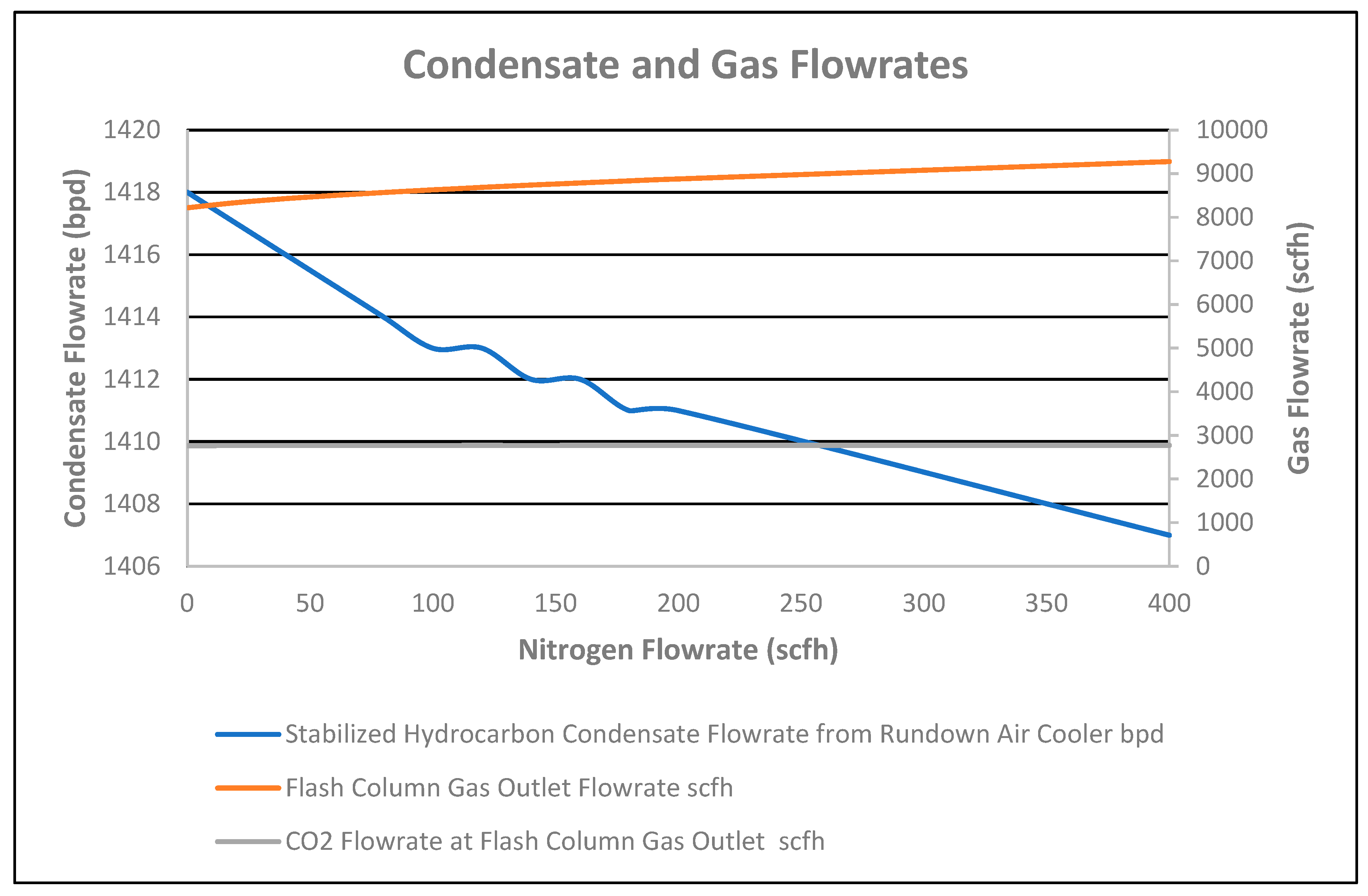
4.2. Scenario 2: Stripping Nitrogen in the Additional Stripping Column Installed at the Bottom of the Reboiler

The stabilized condensate flowrate at the air cooler outlet decreased by 11 bpd for the 0 to 400 scfh nitrogen stripping flowrate, added in the additional two-stage column installed at the reboiler outlet, as shown in Figure 9.
As the temperature was fixed at 160 °F at the outlet of the feed bottom heat exchanger, the duty of the exchanger was constant at 0.7897 MMBtu/hr, as shown in Figure 10, for the 0 to 400 scfh stripping nitrogen flowrate. However, duties of 6.95% and 15.32% for the reboiler and air cooler decreased, respectively, for the 0 to 400 scfh nitrogen stripping flowrate, as shown in Figure 10.
Therefore, the total heat duty requirement of all heat exchangers decreased by 0.21 MMBtu/h for the 0 to 400 scfh nitrogen flowrate, as shown in Figure 10. This is due to nitrogen added in the column, which decreases the partial pressure of the condensate, causing a reduction in the duty of the reboiler. Consequently, CO2 in the stabilized condensate at the cooler outlet decreased from 160 ppmv to 7 ppmv for the nitrogen flowrate of 0 to 400 scfh, respectively, as shown in Figure 11. Therefore, a 5 °F temperature decrease of the stabilized condensate at the reboiler outlet was observed for the nitrogen flowrate of 0 to 400 scfh, as shown in Figure 10.
As nitrogen was added to the column, nitrogen composition at the flash column gas outlet was increased by 3.21 mol%, as shown in Figure 11. The nitrogen composition at the inlet of the stabilizer column without nitrogen injection in the additional stripping column was 0.1 mol%.
CO2 flowrate in the flash column gas outlet increased by 7 scfh for the 0 to 400 scfh nitrogen flowrate, as shown in Figure 9. However, a 3.76% decrease in CO2 composition in the flash column gas outlet occurred due to the nitrogen % increase in the gas outlet for the 0 to 400 nitrogen striping flowrate, as shown in Figure 11. As CO2 and nitrogen flowrates increased in the flash column gas outlet, the total flash gas increased by 1059 scfh for the nitrogen flowrate of 0 to 400 scfh, as shown in Figure 9. Correspondingly, the temperature of the flash column gas outlet slightly increased by 1 °F due to no reflux and the high flash gas flowrate for the 0 to 400 scfh nitrogen striping flowrate, as shown in Figure 10.

4.3. Scenario 3: Same Separator and Column Gas Outlet Pressure for Different Column Pressure Operations

The stabilized condensate flowrate at the air cooler outlet increased by 9 bpd for changes of column pressure from 55 to 120 psig to achieve the same separator and column gas outlet pressure from 25 to 105 psig, as shown in Figure 12.
As the temperature was fixed at 160 °F at the outlet of the feed bottom heat exchanger, the duty of the exchanger was constant at 0.7897 MMBtu/h, as shown in Figure 13 for changes in column pressure. The duty of the reboiler increased by 0.869 MMBtu/h, as shown in Figure 13. Due to changes in the stabilized condensate flowrate and pressure of the column, the air cooler duty increased by 0.88 MMBtu/h, as shown in Figure 13. Therefore, the total heat duty of exchangers increased by 1.75 MMBtu/h.
Increasing temperatures of 8 °F for the flash column gas outlet and 85 °F for the condensate at the reboiler outlet were observed due to column pressure changes, as shown in Figure 13.
As CO2 composition in the stabilized condensate at the cooler outlet decreased from 160 ppmv to 126 ppmv, correspondingly, an increase in CO2 composition in the flash column gas outlet was seen, by 1.7 mol%, respectively, as shown in Figure 14. Therefore, the CO2 flowrate in the flash column gas outlet increased by 1 scfh, as shown in Figure 12. However, the total flowrate of the flash column gas outlet decreased by 391 scfh due to an increase of the stabilized condensate flowrate by 9 bpd at the rundown air cooler outlet.

4.4. Scenario 4: Dynamic Simulation of the Condensate Stabilization Process at 1500 Bpd Flowrate at the Outlet of Flash Separator to Analyze Plant Behavior

Dynamic simulation has been prepared from the basic four-stage column of the steady state simulation to check the process conditions before the plant installation at the site, as shown in Figure 5. It also helped to find out plant conditions at any flowrate.
Steady-state and dynamic simulation data are provided in Table A1. The values of the PID parameters for the controllers have been provided in Table A2. Each PID controller targets different control variables by manipulating different parameters, as indicated in Table A2. Initially, the base case steady-state simulation is considered as being provided in scenario 1, the straight-through flowrate having a top stage and bottom stage column pressure of 55 psig and 58 psig, respectively, for comparison with dynamic simulation. The results have been provided in Table A1. The maximum percentage deviation for the heat duty of the rundown cooler was found to be 7.11% among all heat exchangers used in the above-mentioned scheme. Value differences in the percentage for some parameters were 1.25% for CO2 in the condensate outlet from the cooler, 0.76% for gas flowrate from the column outlet, and 0.14% for condensate flowrate from the cooler outlet.
To reduce the differences in readings, steady-state simulation was again performed for the top-stage and bottom-stage column pressure of 55 psig and 55.05 psig, respectively, the same as that considered for dynamic simulation. The results are provided in Table A1 with good approximation, as the percentage deviation has reduced. The maximum percentage deviation of the heat duty for the rundown cooler was 0.31% among all heat exchangers used. The percentage deviation for other parameters were 1.89% for CO2 in the condensate outlet from the cooler, 0.76% for the gas flowrate from the column outlet, and 0.14% for the condensate flowrate from the cooler outlet.

4.5. Scenario 5: Validation of the Aspen Hysys Simulated Model against the Actual Plant Operating Data at 145 Bpd Flowrate in the Outlet of the Flash Separator

The validity of the Aspen HYSYS simulation model of the condensate stabilization scheme was checked by comparing RVP and process variable values in simulations with the actual plant conditions received from the plant during performance testing at a 145 bpd flowrate at the outlet of the feed bottom heat exchanger. Simulated values, actual plant values, and percentage error are present in Table 3.
Although the condensate stabilization unit was designed on a 1500 bpd flowrate at the outlet of the flash separator, it was tested at a 145 bpd flowrate at the outlet of feed bottom heat exchanger before LCV-9305 as the FIT was placed here. Composition analysis during performance testing was not carried out at the inlet and outlet of the units. However, RVP at the inlet of the flash separator and the outlet of the rundown cooler was measured at the plant and is reported in Table 3.
Therefore, the steady-state HYSYS simulation model was again prepared for 9.5 psia RVP at the inlet of the flash separator instead of 54.4 psia (39.7 psig), by assuming the composition shown in Table A3 to match the RVP values at the actual inlet temperature and the pressure of 103 °F and 140 psig.
The same 119 °F at the outlet of the feed bottom heat exchanger value was considered as the actual value received from the site; 55.3 psig top and 55.5 psig bottom stage pressure of the flash column was considered in the simulation as per actual plant data received. The heat duty in the reboiler was calculated to consider the same 5.6 psia RVP at the outlet of the stabilizer reboiler or rundown cooler instead of 7 psia RVP designed condition. The condensate temperature at the inlet of the stabilizer reboiler showed a 0.24% error, which is the highest error among other flash columns and stabilizer reboiler temperatures.

5. Conclusions

Condensate stabilizer plants require continuous upgradation depending upon the feed conditions to increase production without compromising quality. In the present study, different schemes based on the fractionation method were applied to select the best technique to achieve stabilization with CO2 removal using Aspen Hysys simulation. The following has been concluded from the results:
(1)
CO2 in condensate at the rundown cooler outlet was decreased in descending order from the scenario straight-through flow (160 ppmv), different column pressure (126 ppmv), 100% split ratio (19 ppmv), and nitrogen stripping method (7 ppmv) at 400 scfh. Therefore, the nitrogen stripping method is the best method to select as the technique to reduce CO2 in the condensate.
(2)
The total heat duty keeping the optimum CO2 specification in the condensate at the rundown cooler outlet was decreased in descending order from different column pressure (4.65 MMBtu/h), 100% split ratio (3.638 MMBtu/h), straight-through (2.9 MMBtu/h), and nitrogen stripping (2.69 MMBtu/h). Therefore, the best method for less total heat duty requirement is the nitrogen stripping method.
(3)
The stabilized condensate flowrate recovered at the outlet of the rundown cooler is observed in a decreasing trend from 100% split ratio (1436 bpd), different column pressure (1427 bpd), straight-through flow (1418 bpd), and nitrogen stripping method (1407 bpd). Therefore, a maximum 29 bpd flowrate recovery variation was observed.
(4)
Since a close resemblance between the steady state and dynamics simulation results has been found, dynamic simulation shall be used to analyze plant conditions for specific conditions before implementation in operation.
(5)
For result validation, a 0.24% discrepancy between the Aspen Hysys data and actual plant data was calculated, which shows the validity of the simulated values.
Hence, keeping in view the recovery of the stabilized condensate flowrate at the rundown cooler outlet among CO2, heat duties, and unit operability for same RVP value, the best method selected is the nitrogen stripping method.

Author Contributions

M.E. (Software; Validation; Roles/Writing—original draft), U.A. (Supervision; Writing—review & editing), F.S. (Formal analysis; Writing—review & editing) H.M.A. (Resources—Plant data), M.F.U.B. (Formal analysis; Writing—review & editing). All authors have read and agreed to the published version of the manuscript.

Funding

This research did not receive any specific grant from funding agencies in the public, commercial or not-for-profit sectors. The authors thank the Department of Chemical Engineering (UET, Lahore, Pakistan) for providing the facilities for simulation work.

Data Availability Statement

Data if any is available in Appendix A.

Conflicts of Interest

The lead author and co-author solely declare that they do not have any conflict with any party for the declaration of the present research result/work.

Appendix A

Table A1. Dynamic and Steady State Simulation Comparison.
Dynamic and Steady State Simulation Comparison
ConditionsUnitsSteady State Simulation Case with Different Column Pressure Drop to Dynamic Simulation CaseDynamic Simulation CaseDifference in Percentage of Dynamic Simulation Reading from Steady State Simulation ReadingSteady State Simulation Case with Same Column Pressure Drop to Dynamic Simulation CaseDifference in Percentage of Dynamic Simulation Reading from Steady State Simulation Reading Column Pressure Drop
Flash Separator
Inlet two phase stream condensate flowrate to Separator bpd182218210.05418220.05
Condensate outlet flowrate from Separator bpd15001500015000.00
Water outlet flowrate from Separator bpd00-00.00
Gas outlet flowrate from Separator scfh35,90035,8300.19535,9000.19
Temperature of Separator°F69.1468.550.85369.140.85
Pressure of Separatorpsig140140.5−0.357140−0.36
Water mole fraction of condensate at inlet of Separator mol fraction0.00090.000900.00090.00
CO2 mole fraction of condensate at inlet of Separator mol fraction0.16720.167200.16720.00
Water mole fraction of gas at outlet of Separator mol fraction0.00180.001800.00180.00
CO2 mole fraction of gas at outlet of Separator mol fraction 0.33540.335400.33540.00
Feed Bottom Heat Exchanger
Condensate inlet temperature to Heat Exchanger from Separator °F69.1468.510.9169.140.91
Condensate outlet temperature from Heat Exchanger towards Column before LCV °F160159.80.1251600.12
Condensate inlet temperature to Heat Exchanger from Column °F304.9299.91.64299.8−0.03
Condensate outlet temperature from Heat Exchanger towards Cooler before LCV °F220.5214.62.68214.90.14
Condensate inlet pressure from Separator to Heat Exchanger psig140141.2−0.86140−0.86
Condensate outlet pressure from Heat Exchanger towards Column Before LCV psig130132.3−1.77130−1.77
Condensate inlet pressure from Column to Heat Exchanger psig5855.614.1255.05−1.02
Condensate outlet pressure from Heat Exchanger towards Cooler Before LCV psig5351.722.4250.05−3.34
Heat Exchanger DutyMMBtu/hr.0.78970.7925−0.350.7897−0.35
Flash Column
Inlet condensate flowrate to Columnbpd145114430.55114510.55
Inlet gas flowrate to Column scfh51715889−13.895171−13.89
Condensate outlet flowrate from Reboiler towards Feed Bottom Heat Exchangerbpd141814160.1414180.14
Gas flowrate outlet from Column scfh82198282−0.768220−0.75
Condensate temperature after LCV at inlet of Column °F156.8155.40.89156.80.89
Gas temperature at outlet of Column °F156.21560.13156.30.19
Condensate temperature at outlet of Column °F304.9299.91.64299.8−0.03
Gas pressure at outlet of Column psig5555.02−0.03655−0.04
Condensate pressure from reboiler toward Feed Bottom Heat Exchangerpsig5855.614.1255.05−1.02
Column top stage pressurepsig55550550.00
Column bottom stage pressurepsig5855.055.0955.050.00
Water mole fraction in gas from Column outlet mol fraction0.00190.001900.00190.00
CO2 mole fraction in gas from Column outletmol fraction0.33640.33640.000.33640.00
Stabilizer Reboiler
Condensate inlet flowrate towards Reboilerbpd169416780.941677−0.06
Gas outlet flowrate towards Column from Reboilerscfh13,83013,1305.0613,080−0.38
Condensate inlet temperature towards Reboiler°F207.7204.31.64204.30.00
Gas outlet temperature towards Column from Reboiler°F304.9299.91.64299.8−0.03
Condensate inlet pressure towards Reboilerpsig5855.095.0255.05−0.07
Gas outlet pressure towards Column from Reboilerpsig5855.085.0355.05−0.05
Reboiler DutyMMBtu/hr.1.3811.3333.481.331−0.15
Rundown Cooler
Condensate flowrate from Feed Bottom Heat Exchanger to Rundown Coolerbpd141814160.14114180.14
Condensate inlet temperature from Feed Bottom Heat Exchanger to LCV towards Rundown Cooler°F220.5214.62.68214.90.14
Condensate inlet temperature from LCV to Rundown Cooler inlet°F220.6214.82.63215.10.14
Condensate outlet temperature from Rundown Cooler °F135134.90.0741350.07
Condensate inlet pressure from Feed Bottom Heat Exchanger before LCV towards Rundown Coolerpsig5351.722.4250.05−3.34
Condensate inlet pressure from LCV to Rundown Cooler inletpsig22220.00220.00
Condensate outlet pressure from Rundown Cooler psig17170170.00
Rundown Cooler DutyMMBtu/hr.0.73020.67837.110.68040.31
RVP at Rundown Cooler outletpsia77070.00
Water mole fraction in condensate of Rundown Cooler outletmol fraction 0.000001450.000001450.000.00000143−1.40
CO2 mole fraction in condensate of Rundown Cooler outlet mol fraction 0.0001600.000162−1.250.000159−1.89
Table A2. PID Parameters for Controllers.
ControllersKCTi (min)
Flash separator water level controller210
Flash separator condensate level controller25
Flash separator condensate flow controller1.57
Flash separator pressure controller22
Condensate stabilizer column pressure controller22
Stabilizer Reboiler level controller21
Table A3. Composition for Actual Plant Validation.
ComponentsMole%ComponentsMole%
Nitrogen0.1n-C120.0
CO20.1n-C130.0
H2S0.00n-C140.0
Methane0.01n-C150.0
Ethane0.01n-C160.0
Propane0.3n-C170.0
i-Butane0.88n-C180.0
n-Butane0.9n-C190.0
i-Pentane15n-C200.0
n-Pentane9n-C210.0
n-Hexane48.03n-C220.0
MCyclopentane0.5n-C230.0
Benzene0.0n-C240.0
Cyclohexane0.1n-C250.0
n-Heptane0.0n-C260.0
MCyclohexane0.1n-C270.0
Toluene0.0n-C280.0
n-Octane25n-C290.0
E-Benzene0.0n-C300.0
m-Xylene0.0n-DotriC320.0
p-Xylene0.0n-HexatriC300.0
o-xylene0.0H200.07
n-Nonane0.0
n-Decane0.0
n-C110.0

References

  1. Rahmanian, N.; Jusoh, L.S.B.; Homayoonfard, M.; Nasrifar, K.; Moshfeghian, M. Simulation and optimization of a condensate stabilisation process. J. Nat. Gas Sci. Eng. 2016, 32, 453–464. [Google Scholar] [CrossRef]
  2. Uwitonze, H.; Hwang, K.S.; Lee, I. Modelling and improving natural gas condensate process with stripping and heat integration. Chem. Eng. Process. Process Intensif. 2017, 118, 71–77. [Google Scholar] [CrossRef]
  3. Rahmanian, N.; Bin Ilias, I.; Nasrifar, K. Process simulation and assessment of a back-up condensate stabilization unit. J. Nat. Gas Sci. Eng. 2015, 26, 730–736. [Google Scholar] [CrossRef]
  4. Rahmanian, N.; Aqar, D.Y.; Bin Dainure, M.F.; Mujtaba, I.M. Process simulation and assessment of crude oil stabilization unit. Asia-Pac. J. Chem. Eng. 2018, 13, e2219. [Google Scholar] [CrossRef]
  5. Bhran, A.A.E.-K.; Hassanean, M.H.; Helal, M.G. Maximization of natural gas liquids production from an existing gas plant. Egypt. J. Pet. 2016, 25, 333–341. [Google Scholar] [CrossRef]
  6. Hajizadeh, A.; Mohamadi-Baghmolaei, M.; Azin, R.; Osfouri, S.; Heydari, I. Technical and economic evaluation of flare gas recovery in a giant gas refinery. Chem. Eng. Res. Des. 2018, 131, 506–519. [Google Scholar] [CrossRef]
  7. Kazerooni, N.M.; Adib, H.; Sabet, A.; Adhami, M.A.; Adib, M. Toward an intelligent approach for H 2 S content and vapor pressure of sour condensate of south pars natural gas processing plant. J. Nat. Gas Sci. Eng. 2016, 28, 365–371. [Google Scholar] [CrossRef]
  8. Zhu, L.; Liu, H.; Zhang, Z.; Pu, Y. Simulation analysis of stripping fractionation process of gas condensate treatment and practical application. J. Nat. Gas Sci. Eng. 2016, 34, 216–225. [Google Scholar] [CrossRef]
  9. Shankar, N.; Sivasubramanian, V.; Arunachalam, K. Steady state optimization and characterization of crude oil using Aspen HYSYS. Pet. Sci. Technol. 2016, 34, 1187–1194. [Google Scholar] [CrossRef]
  10. Bassane, J.F.P.; Sad, C.M.; Neto, D.M.; Santos, F.D.; Silva, M.; Tozzi, F.C.; Filgueiras, P.R.; de Castro, E.V.; Romão, W.; Santos, M.F.; et al. Study of the effect of temperature and gas condensate addition on the viscosity of heavy oils. J. Pet. Sci. Eng. 2016, 142, 163–169. [Google Scholar] [CrossRef]
  11. Adib, H.; Sabet, A.; Naderifar, A.; Adib, M.; Ebrahimzadeh, M. Evolving a prediction model based on machine learning approach for hydrogen sulfide removal from sour condensate of south pars natural gas processing plant. J. Nat. Gas Sci. Eng. 2015, 27, 74–81. [Google Scholar] [CrossRef]
  12. Brahim, A.O.; Abderafi, S.; Bounahmidi, T. Modeling the stabilization column in the petroleum refinery. Energy Procedia 2017, 139, 61–66. [Google Scholar] [CrossRef]
  13. Brahim, A.O.; Abderafi, S. Pressure Effect on the Stabilization Column in the Petroleum Refinery. Energy Procedia 2017, 118, 233–237. [Google Scholar] [CrossRef]
  14. Mourad, D.; Ghazi, O.; Noureddine, B. Recovery of flared gas through crude oil stabilization by a multi-staged separation with intermediate feeds: A case study. Korean J. Chem. Eng. 2009, 26, 1706–1716. [Google Scholar] [CrossRef]
  15. Afanas, I.P.; Minkhairov, M.F. Improvement of Indicators for the Motor-Fuel Refinery at the Surgut Condensate-Stabilization Plant. Chem. Pet. Eng. 2000, 36, 9–11. [Google Scholar]
  16. Moaseri, E.; Mostaghisi, O.; Shahsavand, A.; Bazubandi, B.; Karimi, M.; Ahmadi, J. Experimental study and techno-economical evaluation of Khangiran sour natural gas condensate desulfurization process. J. Nat. Gas Sci. Eng. 2013, 12, 34–42. [Google Scholar] [CrossRef]
  17. Bahmani, M.; Shariati, J.; Rouzbahani, A.N.; Babakhani, S.M. Simulation and optimization of an industrial gas condensate stabilization unit to modify LPG and NGL production with minimizing CO2 emission to the environment. Chin. J. Chem. Eng. 2017, 25, 338–346. [Google Scholar] [CrossRef]
  18. Moghadam, N.; Samadi, M.; Hosseini, Z.B.M. Simulation of Gas Condensate Stabilization Unit Aiming at Selecting the Right Technique and Assessing the Optimized Operational Parameters. In Proceedings of the International Conference on Chemical, Biological and Environmental Engineering, Singapore, 26–28 February 2012; Volume 43, pp. 78–82. [Google Scholar]
  19. Tavan, Y.; Hosseini, S.H.; Ahmadi, G. Energy and exergy analysis of intensified condensate stabilization unit with water draw pan. Appl. Therm. Eng. 2019, 155, 49–58. [Google Scholar] [CrossRef]
  20. Karimkhani, B.; Khorrami, Z.; Pars, S.; Complex, G. SPE 127397 Evaluating Effect of Different Operational Parameters on Increasing Performance of Condensate Stabilizing Process in Gas Plants (Case Study). In SPE Kuwait International Petroleum Conference and Exhibition; SPE: Richardson, TX, USA, 2009; pp. 1–8. [Google Scholar]
  21. Moghadam, N.; Samadi, M. Gas Condensate Stabilization Unit: Different Design Approaches. Int. J. Chem. Eng. Appl. 2012, 3, 461–465. [Google Scholar] [CrossRef]
  22. Jahromi, E.E.; Esmaeilani, L.; Sadeghifard, S. Shutdown Reduction Methods for Compressors in Condensate Stabilization Units. In Proceedings of the 2012 7th International Conference on System of Systems Engineering (SoSE), Genova, Italy, 16–19 July 2012. [Google Scholar]
  23. Long, N.V.D.; Lee, M. A novel NGL (natural gas liquid) recovery process based on self-heat recuperation. Energy 2013, 57, 663–670. [Google Scholar] [CrossRef]
  24. Spoelstra, S. Heat pumps in distillation. In Proceedings of the Distillation & Absorption Conference, Eindhoven, The Netherlands, 12–15 September 2010; pp. 12–15. [Google Scholar]
  25. Tahouni, N.; Khoshchehreh, R.; Panjeshahi, M.H. Debottlenecking of condensate stabilization unit in a gas refinery. Energy 2014, 77, 742–751. [Google Scholar] [CrossRef]
  26. De Rijke, A. Development of a Concentric Internally Heat Integrated Distillation Column. Ph.D. Thesis, Technische Universiteit Deft, Delft, The Netherlands, 2007. [Google Scholar]
  27. Mokhatab, S.; Poe, W.A.; Mak, J.Y. Handbook of Natural Gas Transmission and Processing: Principles and Practices; Gulf Professional Publishing: Cambridge, MA, USA, 2018. [Google Scholar]
Figure 1. Flow schematic of the conventional straight-through condensate stabilization process where, green lines indicate process flowsheet inputs and outputs, blue lines indicate the in-process streams and grey lines are control lines.
Chemengineering 07 00078 g001
Figure 2. Flow schematic of the split-flow condensate stabilization process (color scheme is same as of Figure 1).
Chemengineering 07 00078 g002
Figure 3. Flow schematic of the stripping Nitrogen Condensate Stabilization Process (color scheme is same as of Figure 1).
Chemengineering 07 00078 g003
Figure 4. Different Column Pressure Operation (color scheme is same as of Figure 1).
Chemengineering 07 00078 g004
Figure 5. Dynamic simulation scheme (color scheme is same as of Figure 1).
Chemengineering 07 00078 g005
Figure 6. Condensate and gas flowrate vs. split ratio.
Chemengineering 07 00078 g006
Figure 7. Heat exchanger duties and temperature vs. split ratio.
Chemengineering 07 00078 g007
Figure 8. CO2 compositions vs. split ratio.
Chemengineering 07 00078 g008
Figure 9. Condensate and gas flowrates vs. nitrogen flowrate.
Chemengineering 07 00078 g009
Figure 10. Heat duties and temperature vs. nitrogen flowrate.
Chemengineering 07 00078 g010
Figure 11. Nitrogen and carbon dioxide compositions vs. nitrogen flowrate.
Chemengineering 07 00078 g011
Figure 12. Condensate and gas flowrates vs. separator and column gas outlet pressure.
Chemengineering 07 00078 g012
Figure 13. Heat exchanger duties and temperature vs. separator and column gas outlet pressure.
Chemengineering 07 00078 g013
Figure 14. Carbon dioxide compositions vs. separator and column gas outlet pressure.
Chemengineering 07 00078 g014
Table 1. Feed conditions.
ParametersValues
Inlet pressure (psig)140
Inlet temperature (°F)69.14
Condensate flow (bpd)
(downstream of stabilizer inlet flash separator)
1500
Table 2. Feed composition.
ComponentsMole%ComponentsMole%
Nitrogen2.42n-C141.10
CO216.72n-C151.05
H2S0.00n-C160.82
Methane19.37n-C170.56
Ethane5.92n-C180.49
Propane4.14n-C190.42
i-Butane1.06n-C200.36
n-Butane2.11n-C210.32
i-Pentane1.33n-C220.19
n-Pentane1.36n-C230.16
n-Hexane3.02n-C240.14
MCyclopentane0.57n-C250.12
Benzene0.57n-C260.10
Cyclohexane0.59n-C270.09
n-Heptane6.21n-C280.07
MCyclohexane2.08n-C290.06
Toluene2.15n-C300.15
n-Octane5.86n-DotriC320.07
E-Benzene0.17n-HexatriC300.09
m-Xylene0.76H2O0.09
p-Xylene0.76
o-xylene0.52
n-Nonane5.16
n-Decane4.44
n-C112.80
n-C121.94
n-C131.51
Table 3. Validation of performance test data.
Validation of Performance Test Data
ConditionsUnitsSteady State Simulation ValuesActual Plant DataDifference in Percentage of Steady-State Simulation Values from Actual Plant Data
Flash Separator
RVP of condensate at inlet of separator psia9.59.50.00
Pressure of separatorpsig1401400.00
Feed Bottom Heat Exchanger
Condensate temperature at inlet of feed Bottom heat exchanger°F1031030.00
Condensate temperature at outlet of feed Bottom heat exchanger towards column before LCV°F1191190.00
Condensate temperature at inlet of heat exchanger from column°F2692690.00
Flash Column
Flash column top stage pressurepsig55.355.30.00
Flash column bottom stage pressurepsig55.555.50.00
Stabilizer Reboiler
Condensate temperature at inlet of stabilizer reboiler°F250.42510.24
Gas temperature at outlet of stabilizer reboiler towards column °F268.92690.04
Hot oil temperature at inlet of stabilizer reboiler°F3053050.00
Hot oil temperature at outlet of stabilizer reboiler°F2962960.00
Hot oil pressure at inlet of stabilizer reboilerpsig77770.00
Rundown Cooler
Condensate flowrate from feed bottom heat exchanger to rundown coolerbpd1451450.00
Condensate temperature at outlet of rundown cooler °F91910.00
RVP at outlet of rundown coolerpsia5.65.60.00
Disclaimer/Publisher’s Note: The statements, opinions and data contained in all publications are solely those of the individual author(s) and contributor(s) and not of MDPI and/or the editor(s). MDPI and/or the editor(s) disclaim responsibility for any injury to people or property resulting from any ideas, methods, instructions or products referred to in the content.

