1. Introduction
While the cities that are located in a hot environment suffer from high temperature during spring and summer, the required cooling power can be compensated through solar radiation [
1,
2]. Using solar-powered cooling systems can considerably reduce electricity and fossil fuels consumption. Adsorption phenomenon is the most eco-friendly process to generate cooling from environmental heat due to the following reasons [
3,
4,
5]:
In addition, the adsorption cooling systems have some advantages over the other types of cooling systems as follows [
6,
7]:
Unlike mechanical vapor compression systems (MVCs), the adsorption cooling systems have no vibration. In addition, the control strategy of an adsorption system is much simpler than MVCs. In addition, adsorption systems have lower operational cost in comparison with MVCs.
Unlike the absorption systems, the adsorption systems do not suffer from corrosion process. They also are less sensitive to the shock and the position of installation.
While the adsorption systems have remarkable advantages over the other types of cooling systems, they have some disadvantages such as a low coefficient of performance (COP) and high initial cost. On the other hand, when the adsorption cooling systems are driven by solar energy, their performance is highly sensitive to the climate situation (obviously overnight or in cloudy weather, the performance degrades dramatically). Hence, these types of cooling systems need an auxiliary heat generation source to guarantee unintrrupted cooling output [
8].
Over the last few years, some researchers have been dedicated to investigating the efficient design of the solar-powered sorption cooling systems in both technical and economic perspectives. The payback period (PBP), net present value (NPV), cost of unit cooling capacity, and annual cost were the main investigated parameters in these studies.
Energetic, economic, and environmental analysis of a solar-powered absorption cooling and heating system in four different configurations was presented by Shirazi et al. [
9]. The authors concluded that while one of the configurations obtains a solar fraction of
and primary energy saving of
compared to the conventional system, the economic performance of the systems still is not satisfactory due to high initial cost.
Al-Ugla et al. [
10] investigated the economic feasibility of three different types of air-conditioning systems for a commercial building in Saudi Arabia. The main purpose of this study was to construct a road map in mitigating the electrical peak power demand by utilizing the solar-powered cooling technologies in a commercial building.
The total energy cost per unit area and total yearly required energy per unit area for cooling purpose are investigated by the authors in [
11]. In this research, different types of cooling systems in different climates in Iran are studied. The results demonstrated that while using an absorption chiller increased the total energy consumption per unit area, however, the total cost of energy per unit area was decreased.
Reda et al. in [
12] investigated the optimization procedure of a small-scale solar-powered adsorption cooling system in Egypt. An approach based on decision support is utilized to choose the best size of the main components of the solar-powered adsorption cooling system with a silica gel and water working pair. The results demonstrate that the initial cost of the cooling system was in the 3322–5514 range. Meanwhile, the annual operational cost achieved low values, and it was in the 16–113 range.
The authors in [
13] compared seven working pairs which are used in adsorption cooling systems. In addition, they introduce an economic figure of merit to compare different adsorbents called mean adsorbent cost (MAC) per kW of cooling capacity.
Bouhal et al. investigated the thermal performance of a solar-powered air conditioning system under Moroccan conditions [
14]. They also investigated the economic feasibility of the system based on the Internal Rate of Return (IRR) and NPV. The results demonstrated that the system has to be supported by the government through subsidization to be an economically feasible project.
As mentioned, the high initial cost of the solar instruments is the main barrier against commercializing solar-powered adsorption cooling systems. Having two different heating sources (solar energy and auxiliary heater driven by electricity) provides a trade-off between cost efficient and eco-friendly design in these systems. Therefore, by considering the carbon dioxide avoidance factor of the solar systems, the high initial cost of the solar-powered system could be justified.
The main contributions of this paper are as follows:
A unified framework is proposed to facilitate the economic investigation of a solar-powered adsorption cooling system. The proposed framework considers environmental benefit through CO2 emission avoidance.
Particle swarm optimization, which is a powerful global optimization tool, is used through the framework to find the optimum solution at each specific scenario.
The rest of this paper is organized as follows: the next two sections are dedicated to related works and mathematical modeling of a typical solar-powered adsorption cooling system. In
Section 4, economic optimization is performed for the solar-powered adsorption cooling system at the cooling load related to a single-family house.
Section 5 is dedicated to the results and discussion. Finally, the paper is concluded in
Section 6.
2. Related Works
In order to choose the appropriate size for the major parts of a small-scale solar-assisted silica gel–water adsorption cooling system in dry areas near Assiut, Egypt, the authors in [
12] offer a decision assistance approach. The solar collector area, the volume of the hot storage tank, the volume of the cold storage tank, and the thermostat set point of the auxiliary heating element have all been optimized based on a computer simulation to fulfill the goal of this study. Additionally, analyses of the suggested systems’ economic and environmental impacts have been carried out in their works. Their findings demonstrate that the surface of the solar collectors with a 5 degree tilt collected solar light the best. The solar fraction did not change the amount of the cold water storage tank for any of the suggested systems, but it significantly changed the area of the solar collector field and the volume of the hot water storage tank. The results demonstrate that the initial cost of the cooling system was in the 3322–5514 range. Meanwhile, the annual operational cost achieved low values, and it was in the 16–113 range.
Another study [
15] looked into a method that could cool a one-story building with a domed roof using a solar-powered adsorption chiller. The effect of geometric elements on air change per hour (ACH), such as the depth of the cooling channel and the size of the input and output vents, was investigated. Additionally, the room temperature was assessed for various values of the ACH and room cooling demand in various environmental situations. The findings demonstrate that ACH can be managed by adjusting the inlet air vent’s size. Additionally, it is observed that when ACH increases, adaptive thermal comfort condition (ATCS) is attained under higher cooling demand levels. Additionally, according to ATCS, using three cooling plates in the channel rather than two improves the maximum cooling requirement for which thermal comfort is attained from 775 to 1295 W. Additionally, when used to cool a building in Bandar Abbas, the suggested system uses 45% less electricity than a split air conditioner of the same capacity.
Under climatic conditions typical of Perth, Australia, the performance of a two-bed silica gel–water adsorption refrigeration system powered by solar thermal energy is evaluated in [
16]. The solar radiation is simulated based on Fourier series. To analyze the system economics and minimize the requirement for solar collector areas, two economic methodologies, Payback Period and Life-Cycle Saving, are applied. A three-order Fourier series was sufficient to simulate the actual solar radiation, according to the research, which revealed that the order of the Fourier series had little bearing on the simulation radiation data. The average cooling capacity of the chiller for a normal summer day is approximately 11 kW at peak hour (13:00), while the cyclic chiller system coefficient of performance (COP) and solar system COP are approximately 0.5 and 0.3, respectively. Economic analysis revealed that the solar adsorption system under study had a payback period of around 11 years and that the ideal solar collector area was approximately 38 m
2 if a compound parabolic collector (CPC) panel was utilized. According to the study, using solar-driven adsorption cooling in climates such as Perth, Australia, is both economically and technically feasible.
For a particular developing nation in the Eastern Mediterranean with a hot and dry climate, a recent [
17] study compared two options: a linked PV and air conditioner system and a solar cooling system (absorption chillers where thermal energy is produced by solar collectors) (Jordan). The PV system had a capacity of 2.1 MWp, the utility grid connection was a 0.4 kV 50 Hz net meter (2 m), and it was expected that 3300 MWh/year would be produced. The cooling system consisted of two cooled multistage compression units, each of which was 700 kW in size. The maximum coefficient of performance (COP) of the solar cooling system was 0.79, and the actual COP on the site was 0.32. The levelized cost of energy (LCOE) values were 0.9 and 2.35/kWh, respectively, when the electricity rate of 0.1/kWh was taken into account. The results show that the solar thermal cooling system and the PV system had startup expenses of about 3.150 M and 3 M, respectively. When discounts of 6% annually were added to the payments for the PV and air conditioning system, the current value of the future cash payments came to roughly 9,745,000, whereas the solar thermal cooling system will not reach the breakeven point at a negative 1,730,000. When compared to the value of the connected PV and air cooling systems, which was less than 0.05/kWh, it is obvious that the absorption chiller did not demonstrate economic viability. These kinds of technologies are under a lot of pressure to maintain their competitiveness in the face of the development of new air conditioning and PV technologies, in addition to the extensive maintenance requirements, the reduced COP, and the practicality and viability of the solar thermal cooling systems.
3. Mathematical Modeling
The overall schematic of the solar-powered adsorption cooling system is shown in
Figure 1. As shown in the figure, the system includes three main cycles:
- (I)
hot water cycle;
- (II)
cooling water cycle; and
- (III)
chilled water cycle.
Figure 1.
The overall schematic of the solar-powered adsorption cooling system.
Figure 1.
The overall schematic of the solar-powered adsorption cooling system.
The hot water cycle consists of two sub-cycles. In the first sub-cycle, the solar collector supplies hot water to the storage tank. This hot water is used to drive the adsorption chiller. When the hot water temperature drops below the predefined threshold temperature, the auxiliary heater (the second sub-cycle) provides the remaining required heat. The cooling water cycle is necessary to remove the produced heat during the desorption process from the adsorption chamber. In order to accelerate the water-cooling process, a cooling tower is usually utilized. Finally, the chilled water coming from the evaporator is used to cool down the building temperature.
In a typical solar-powered cooling system, the major portion of the required heat is provided by solar collectors. The efficiency of a solar collector is expressed as [
18]:
where
is solar radiation.
,
a and
b are the constants which depend on the geometry and type of the solar collector. Typical values of these parameters for the flat plate solar collector are reported in
Table 1.
is the difference between the average collector temperature (
) and ambient temperature (
) [
19]:
where
and
stand for the inlet and outlet water temperature of the collector, respectively.
The actual useful heat can be expressed as:
where
,
, and
denote the collector area, the water flow rate of the collector and the specific heat capacity of the water, respectively.
stands for the Heaviside step function, which is defined as:
When the heat loss is greater than zero-loss efficiency (), the collector efficiency drops below zero. In this case, the solar collector does not increase the hot water temperature and may decrease the water temperature, yet. Hence, the step function is used to eliminate negative values of the collector efficiency. In fact, the step function can be considered as a power-on-switch for the collector pump.
An energy balance on the storage tank gives [
20]:
where
,
,
,
, and
denote the mass of water in the storage tank, the tank temperature, heat removal from the storage tank due to cooling load to the adsorption chiller, the overall heat transfer coefficient of the storage tank and the storage tank area, respectively.
For a certain cooling load (
), the total required heat (
) can be provided through the storage tank (
) and auxiliary heater (
):
When the hot water temperature falls below the certain temperature (
), both COP and cooling capacity approach zero [
21]. Therefore, the maximum usable heat in the storage tank which can be supplied to the adsorption chamber is calculated as:
where
denotes the mass flow rate of hot water.
stands for heat exchanger effectiveness and can be calculated as [
22]:
where
and
denote the overall heat transfer coefficient of the adsorption chamber and the area of the adsorption chamber, respectively.
Finally, the heat removal from the storage tank due to cooling load to the adsorption chiller (
) is defined as:
When silica gel is used as the adsorbent, there is an upper bound for the hot water temperature. If the hot water temperature exceeds this limit, the silica gel would lose the adsorption capability. Thus, the desorption temperature cannot be higher than 120 °C, and it is generally about 90 °C [
23]. Using this assumption and performing finite difference approximation to Equation (
5), the whole system of equations can be solved, explicitly. The procedure for solving this system is demonstrated in
Figure 2.
Cooling Load Calculation
In order to calculate the hourly cooling load, a 144 m
2 single-family building is designed in EnergyPlus (
https://energyplus.net/ (accessed on 8 October 2022)) 8.9 environment. Using the Isfahan weather file [
24], the hourly cooling load profile of the designed building is calculated (
Figure 3). The surface constructions and window properties data are extracted from [
25].
5. Results and Discussion
In this section, simulation results are provided to investigate the economic feasibility of the solar-powered adsorption cooling system. The simulations are performed in the MATLAB environment. The simulation parameters are reported in
Table 5. At the first step, the partial and overall costs of the system for both base and optimum cases are calculated. The values of the main variables in the base and optimum cases are reported in
Table 6. As reported in the table, in the cost-efficient design, the optimizer algorithm (PSO ) reduces both the solar collector area and storage tank volume, while it increases the mass flow rate of hot water. A reasonable explanation for this behavior is that the optimizer algorithm is trying to reduce the solar contribution in the total useful delivered heat to the adsorption chamber due to the relatively higher price of the solar collector. Therefore, after the optimization process, the cost of the solar collector as well as the storage tank take lower values compared to the base case. On the other hand, the higher hot water mass flow rate leads to a higher pump cost (
Table 6). The cost percentage for different parts of the solar-powered cooling system for both the base and optimum cases are depicted in
Figure 4.
5.1. Cost-Efficient Scale Selection
In this section, an economic analysis for different cooling loads is performed to investigate the cost-efficient scale selection. To this end, Equation (
10) is optimized for different cooling loads in a 1–300 kW interval and the total cost per 1 kW cooling capacity is calculated. As shown in
Figure 5, the minimum cost per 1 kW cooling capacity is achieved in a 5–10 kW interval. Hence, a solar-powered adsorption cooling system with the configuration similar to what was proposed in this research is suitable for small-scale applications (e.g., single family house). In general, cooling loads less than 50 kW are acceptable choices for this configuration.
Figure 6 shows the storage tank volume and hot water mass flow rate versus different cooling loads. It is worthwhile to mention that the solar collector area does not change over different cooling loads due to its high initial price.
Note that the aforementioned results are given according to the specific input parameters. In general, the whole design procedure can be consider as a unified framework. That is, for a specific configuration, the optimum cooling capacity can be determined. On the other hand, having the desired cooling capacity, the design configuration can be adjusted to have an economically optimized design.
5.2. Sensitivity to Electricity Price
In order to investigate the main bottlenecks of the cost-efficient system design, a sensitivity analysis to electricity price is performed. To this end, Equation (
10) is optimized for different electricity prices (per kWh).
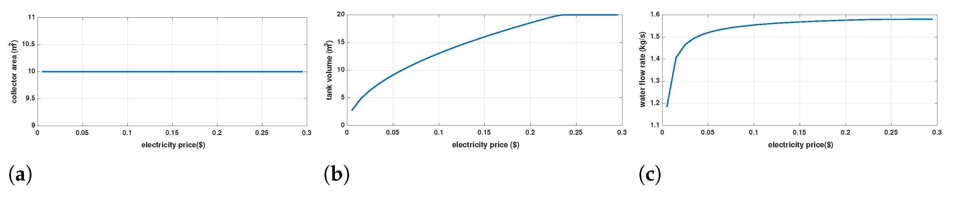
Figure 7 shows the main optimization variables over different electricity prices. As demonstrated in
Figure 7a, while the electricity price is increased by 30 times, the optimization algorithm prefers to minimize the solar fraction due to the high initial cost of the solar collector. In this situation, while the solar collector area is kept at the minimum value, the storage tank volume (
Figure 7b) and hot water mass flow rate (
Figure 7c) are increased to maximize the useful delivered heat to the adsorption chamber.
Considering the previous analysis, one can conclude that the initial cost of the solar collector is the main bottleneck of the cost-efficient solar-powered adsorption cooling system design. Therefore, in the next step, the former sensitivity analysis to electricity price is jointly performed over different initial prices of the solar collector at two different cooling loads (10 and 100 kW ).
Figure 8 shows the main optimization variables (
,
, and
) versus both electricity and collector price. As shown in
Figure 8a,b, when the solar collector price decreases compared to the electricity price, the optimizer algorithm tends to increase solar energy participation in the total energy consumption of the system (solar fraction). For higher electricity prices, the optimizer algorithm is more relaxed in relation to the solar collector price. In addition, at higher cooling loads (
Figure 8b), the system can tolerate higher prices for solar collectors compared to the small-scale systems.
When the solar collector area takes its maximum value (100 ), the optimizer algorithm reduces both the storage tank volume and hot water mass flow rate. This happens because of the intrinsic economical trade-off among solar collector area, storage tank volume, and hot water mass flow rate.
5.3. Environmental Benefit
Figure 9 shows the carbon dioxide (CO
2) emission per capita of Iran [
35]. While Iran is not a major CO
2 emitter in the region, the rapidly increasing rate of CO
2 emission during the past two decades is a critical issue. In this situation, solar energy utilization is a proper choice to replace fossil fuels and reduce the overall CO
2 emissions. Therefore, in this section, the amount of the avoided CO
2 is calculated as a function of the solar collector. The amount of environmental benefit of a solar-powered adsorption system which is gained by saving electricity is expressed as:
where the emission factor of CO
2 (
) is
kg/kWh [
28].
Figure 10 shows the annual avoided CO
2 versus solar collector area for two different cooling loads. As shown in this figure, increasing the solar collector area leads to the more avoidant amount of CO
2. In addition, it can be seen that for a small cooling load (10 kW), the rate of the avoided amount of CO
2 decreases beyond 50
of solar collector area.
The cost of CO
2 capture per ton is almost in the 36–53 range [
36]. According to
Figure 10, utilizing solar energy through a 50
solar collector to drive a 10 kW adsorption cooling system could avoid
ton of CO
2 emission, which in turns leads to 565.2–832.1 environmental benefit cost which can completely compensate extra cost of solar collector in environmental friendly case (
Table 7).
6. Conclusions and Future Works
Adsorption cooling systems have attracted researchers’ attention due to their remarkable specifications. The main advantage of these systems is that the required heat (or at least part of it) can be provided through wasted heat or solar energy. However, commercializing these system faces some difficulties such as low coefficient of performance and high initial cost. In this paper, an economic investigation of a solar-powered adsorption cooling system is presented. After mathematical modeling of the system under investigation, the system is economically optimized for a typical single-family house using particle swarm optimization (PSO). In order to select the most efficient operational scale, the cost per 1 kW of cooling capacity is calculated. The results indicate that small-scale applications is the most proper choice for the system under investigation. Consequently, a sensitivity analysis to electricity price demonstrates that the initial cost of the solar collector is the main bottleneck of the cost-efficient system design. Meanwhile, the relatively high initial cost of the solar collector may decrease economic efficiency, however, considering the cost of CO2 capture and the amount of avoided CO2 through utilizing solar energy justifies the economic feasibility of these systems.
The electricity price in Iran is pretty low compared to other countries. This leads to an optimizer tendency to increasing the auxiliary heat source for regular electricity prices. However, high electricity prices may change the feasible solution space for the optimizer. As a suggestion for future works, the design parameters of a hybrid solar system that includes both solar photovoltaic and solar thermal collectors can be optimized through a similar framework to this work. For both thermal collector and photovoltaic panels, instead of a fixed pose, a powerpoint tracker may be applied to yield the maximum achievable solar energy and increase the solar fraction for medium to large-scale applications.


