1. Introduction
Energy consumption is increasing year by year. Due to the EU’s Energy Union strategy introduced to improve energy efficiency and sustainability, as detailed by J. Malinauskaite et al. [
1], researchers are looking for different solutions to recover waste heat energy [
2,
3,
4,
5]. In both industrial and non-industrial sectors, the use of thermoelectric generators (TEGs) is perfectly in line with this trend. TEGs are amongst the most promising solid-state energy generators. TEG modules directly transform thermal energy into electricity, employing the commonly known Seebeck effect when working between two thermal reservoirs [
6]. They have no moveable materials; they are compact; they are noise-free; and they are suited quite well for solar energy and waste heat conversion to electricity using car exhausts [
7], stoves and PV panels. The phenomena occurring in TEG and possible applications have been extensively discussed by H. Jouhara et al. in [
8].
In some applications, heat exchangers are additionally used to increase the heat exchange surface area and thus improve the thermal performance of the TEG. As noted by H. M. Maghrabie et al. in [
9], heat transfer intensification can take different forms. However, S. Soleimani and S. Eckelsb [
10] drew attention to the relationship between the increase in convective heat transfer surface area and the fluid flow drag then occurring.
It is understood that thermoelectric element (TE) modules are comparatively inefficient. Therefore, different studies have been performed to increase the working performance of the generators, including modifications in the structural properties [
11], changes in the geometry of the legs [
12], enhancing the figure of merit [
13], and optimisation of the mechanical system and functioning temperatures [
8]. Annular TE generators were implemented to enhance the operating performance of thermoelectric generators (TEGs) by altering its geometric structure and parameters, and Fraisse et al. [
14] stated that the variable segment had an effect on thermoelectric performance.
An investigation carried out by Erturun et al. [
12] aimed to study potential effects on the thermo mechanical efficiency and power generation of thermoelectric instruments from different thermoelectric leg geometries. In this way, thermoelectric modules with different leg geometries were simulated and finite element analysis was performed using ANSYS for two different temperature gradients. Each model has been evaluated for its thermal distribution, electricity output, conversion efficiency and thermal stresses in the legs. Due to altering leg geometries, there were significant variations in size and distribution of the thermal stresses in the legs. The report reveals that due to the varied leg configurations, temperature distributions, power outputs and conversion efficiencies were substantially changed, and it also concluded that the differing leg geometry may potentially improve the module. In addition, the researchers have demonstrated that less thermal stress is faced by a leg configuration with rounded curves than those with sharp edges, indicating that the greatest thermal stress accrues in the Rectangular geometry.
Using the Finite Element method, Al-Merbati et al. [
15] carried out a study that investigated the relationship of thermal stress with output power and thermal performance of thermoelectric generators with variable pin leg geometry. For specific geometrical configurations of the unit, it was observed that changing the geometry of the pin increases the variation in temperature in the thermoelectric generator, thus reducing the overall stress levels in the pin. As a result, the life expectancy of the device can be increased by the geometrical configuration of the device pins.
The thermoelectric and mechanical performance of a segmented annular thermoelectric generator (SATEG) was investigated by Samson et al. [
16], who employed three-dimensional finite element analysis. Additionally, the effect of segmented pin geometry on the output of the segmented annular thermoelectric generator was studied and a comparison was made with non-segmented annular thermoelectric generators. The study revealed that when the temperature differential is greater than 100K, the segmented annular thermoelectric generator has a higher efficiency compared to the annular thermoelectric generator (ATEG) with Bismuth telluride material. Moreover, while studying the thermal stresses of segmented annular TEGs, the Von Mises stress has been reported to decrease as the angle between the thermoelectric legs increases.
Computational simulation was used by Tian et al. [
17] to explore the hollow cylindrical TEG configuration as a novel leg arrangement for the thermoelectric module in which the n-type and p-type legs are positioned co-axially within each other. The findings indicate that a rise in hot side temperature will boost the output power and conversion efficiency of the cylindrical thermoelectric generator (CTEG) but decrease the mechanical stability of the device. In comparison, with an improvement in the slanting angle of thermoelectric legs, the overall tension of Von Mises in the legs increases and the power output of the CTEG increases. The increase in the width ratio leads to a boost in output power and a decrease in conversion and energy efficiency.
A theoretical review of the thermoelectric power generator was carried out, and the effects of the geometry of the thermoelectric leg on the efficiency of the system and the production of power were studied by Ahmet and Bekir [
18]. The shape parameter was correlated with the geometric structure of the legs in the device and integrated into the analysis. For different temperature and external load resistance ratios, the effect of the form parameter on the unit performance and power generation was studied. Overall, the efficiency of the thermoelectric generators was found to increase for certain ranges of the shape parameter; nevertheless, it has a negative effect on power generation.
The modeling of a multi-element thermoelectric generator with irreversibility demonstrated a significant predictor of the performance of TEG energy efficiency, exergy efficiency and the system power production [
19].
Ravita and Kaushik [
20] conducted a thermodynamic analysis of a extroversible thermoelectric generator involving the Thomson effect and the influence of leg geometry on the device’s power production and performance. The authors calculated mathematically the power output, irreversibility, energy and exergy efficiency considering the Thomson effect. The finding of the analysis indicated that when the shape parameter was increased from a flat plate TEG to a trapezoidal TEG, the energy and exergy efficiency improved as well.
A research study [
21] used a simulation tool for thermoelectric generators based on steady-state equations and experimental evidence to investigate the efficiency of TEGs with continuous heat through them, and to find the optimal geometric configuration, leading to better performance and lowest material expense. The authors also introduced the electrical characterisation of TEGs for constant-heat and explored the relationship between the maximal power point and the open-circuit voltage, the maximum strength of TEGs with legs of various sizes and numbers and packing factors for different heights.
Since the overall usable heat in most waste heat applications is always constrained, the researchers optimised the efficiency for the most realistic condition and reported that the optimum value for the current would be achieved if the steady state of the open-circuit voltage was twice the load voltage. Overall, the findings show that the packing factor and the clearance space substantially affect the power output of a module with a set amount of thermal power.
The effect of pin leg geometry on the thermal efficiency of the system was thermodynamically developed by Haider et al. [
22]. The effects of dimensionless geometric parameters on efficiency and power production were demonstrated for various temperature ratios and external load resistance ratios. Increasing dimensionless geometric parameters has been found to increase the thermal performance of the device, but the maximum efficiency point does not correspond with the maximum output power point of the device.
A detailed mathematical model was suggested by Linhao et al. [
23] to calculate the optimum leg length and cross-sectional area of the TEG unit and to optimise the peak output capacity. The model suggests that there is an ideal ratio of leg length and leg cross-sectional area for a TEG unit corresponding to the maximum peak output power with a fixed boundary condition, and it is possible to further determine the optimal leg length and cross-sectional area depending on the optimal ratio.
Although comprehensive studies have been conducted to investigate the efficiency of different thermoelectric systems, geometric configurations of variable cross-section thermoelectric legs have not been given sufficient attention throughout the reviewed literature. Therefore, the purpose of this research is to thoroughly investigate the effect and performance of thermoelectric generators with new leg geometries, not previously examined in the literature. The leg geometries studied include the traditional Rectangular shape as a reference module and two new configurations: the Diamond shape and the Cone-based shape. Using COMSOL Multiphysics (COMSOL Ltd., Cambridge, UK) temperature distributions, voltage potential and thermal stress analyses were carried out for the proposed leg configuration (each consisting of two pairs p and n). In addition, the electrical analysis for TEG modules consisting of 128 pairs of legs was conducted for two cases generating the lowest and the highest voltages for a double pair of legs.
2. Equivalent Electric Circuit for TEGs and Boundary Conditions
TEG power generation relies heavily on both the temperature difference over the semiconductor components and the electrical load, according to Seebeck, Peltier and Thomson effects.
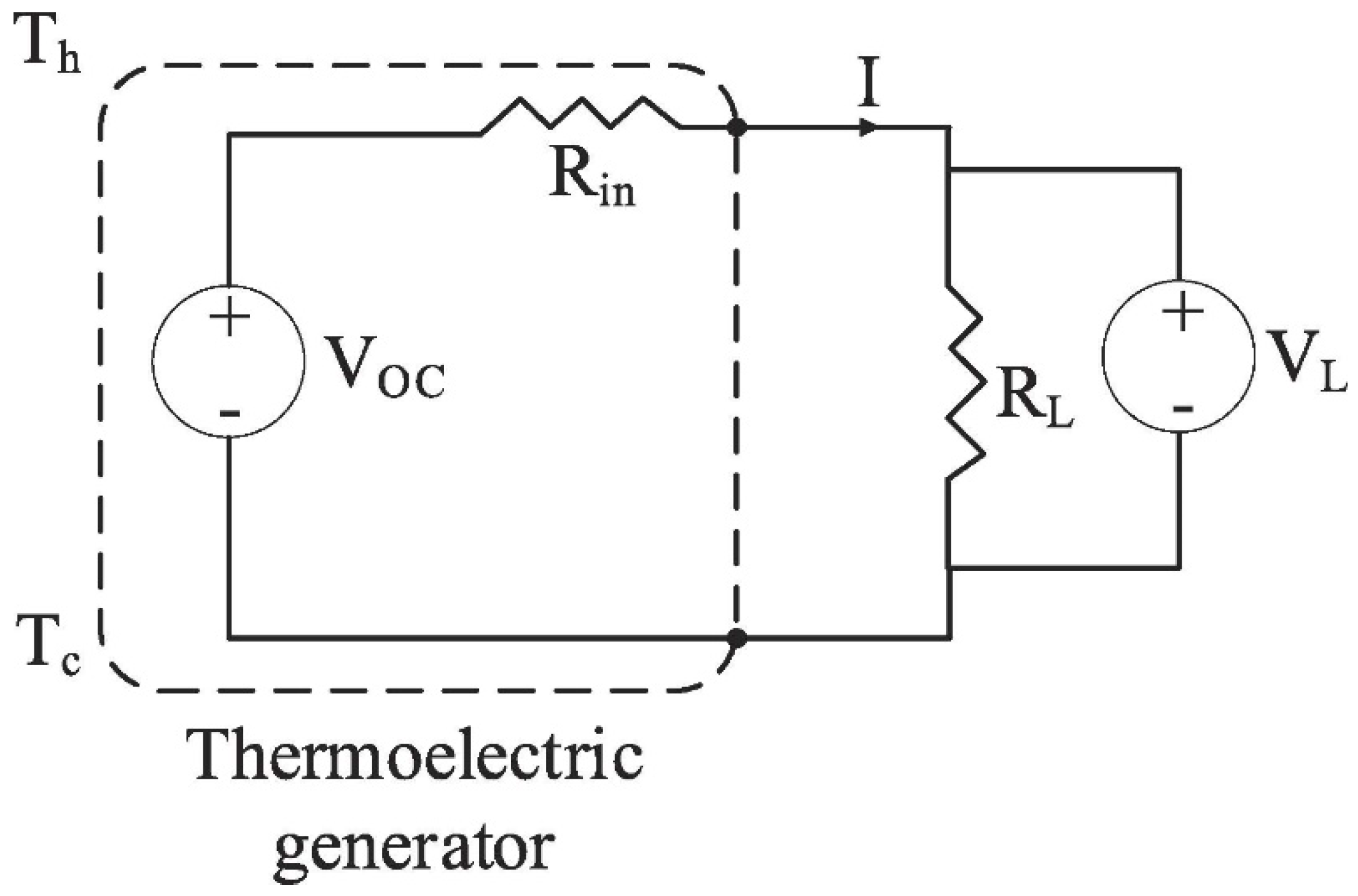
Figure 1 indicates a schematic electric circuit equivalent to the thermoelectric generator. This circuit aims to explain the fundamental objective of the thermoelectric generator. If there is no connection to the load, the open circuit voltage (
) is given as:
where
represents the temperature difference between the hot and cold plates, and the Seebeck coefficient, which is responsible for causing the current to flow (in the case of temperature gradient), is indicated as
.
Once an external load resistance (
) is attached, the output voltage of the thermoelectric generator (
) is defined as the following [
16]:
if
is the TEG’s internal resistance and
is the TEG current, which can be defined as [
16]:
Finally, the thermoelectric generator’s output power
can be obtained from [
24]:
Through integrating many thermoelectric components, the necessary power output for a specific application can be achieved. Furthermore, the output voltage and power of the thermoelectric generator can be maximised [
16] by adding a high temperature differential to the thermoelectric generator and by balancing the external load resistance to its internal resistance.
The efficiency of the thermoelectric generator can be described from Equation (5), where
is the heat input, and it can be obtained using the thermoelectric coupling equations.
In addition to the output power of a thermoelectric generator, the electrical power density is another significant parameter that specifically affects the very critical TEG efficiency and cost ratio for waste heat recovery applications. Means to increase the thermoelectric generator power efficiency involve enhancing the figure of merit, raising the temperature differential around the TEG and optimising thermoelectric element measurements and filling factors [
25].
The Seebeck effect converts temperature differences to electricity, the Peltier effect converts electricity to temperature differences and the Thomson effect is the heat formed by the combination of current density and temperature gradients. The Seebeck coefficient is largely used in the COMSOL formulation. Although the Peltier coefficient is utilised as an intermediate variable, the Thomson coefficient was not employed in the analysis [
26].
2.1. Boundary Conditions
In principle, a TEG unit is a thermopile consisting of a set of semiconductor pairs of p and n type materials connected electrically in series. Heat carries the majority of carriers that produce current and voltage between one connection and another. A TEG module produces an open-circuit voltage proportional to the temperature difference over the components by positioning multiple p and n couples in series electrically and thermally in parallel [
27].
The main boundary conditions for TEG models are described as the following in order to clarify the analysis:
A heat transfer module was used for the measurement of the temperature difference in the thermoelectric generator by conduction and convection with surface-to-surface temperature distribution.
All surfaces except the hot and cold junction surfaces are adiabatic. Therefore, convective heat transfer was not considered for this simulation.
A steady-state condition was assumed for the thermoelectric modules. Addıtıonally, on the surfaces of the TEG, an adiabatic situation is considered, with no heat loss.
Thermal boundary conditions are known as heat source (hot surface) and heat sink (cold surface) with defined temperatures of 293 K and 393 K, respectively, for the cold source and hot surface. In the module, a coherent mesh to describe the electrical and thermomechanical properties was considered.
Internal electrical and thermal contact resistance are neglected.
2.2. Numerical Model
COMSOL Multiphysics is software that allows for the creation of models by defining parameters, building a geometry, applying the physics, creating the mesh, solving the model and then visualising and postprocessing the results.
COMSOL 5.5 Multiphysics software was employed to undertake a finite element analysis and to extract thermoelectric and mechanical performance data from the TEG examined. The analysis was conducted under steady-state conditions. The copper electrode on the cold n-leg surface has zero electrical potential, while a terminal on the cold p-leg is attached to the copper electrode. All materials are known to be linear elastic materials, and
Table 1 lists their corresponding properties. The Seebeck coefficient, electrical resistivity and thermal conductivity, which are temperature-dependent properties of the materials used, are available in COMSOL and presented in the articles [
11,
16,
28].
The principal equation of the thermoelectric analysis was derived through COMSOL Multiphysics 5.5 software, the investigation considers the Peltier effect, Fourier effect, Joule effect and Thomson effect. The heat flow equation in thermoelectric analysis can be written as [
6]:
in which the density is represented as
, the specific heat capacity is shown as
(
,
indicates the heat flux vector,
(
is the heat generation rate per unit volume and
is the absolute temperature.
The continuity of electric charge can be obtained from the equation below [
29]:
where
is the electric current density vector
and
is the electric flux density vector.
Equations (6) and (7) are combined employing appropriate fundamental thermoelectric equations [
30]:
represents the Seebeck coefficient matrix, the thermal conductivity matrix is shown as
and
is the electrical conductivity matrix.
indicates the electric field intensity and it can be deduced from [
30]:
represents the electric scalar potential. Incorporating Equations (8)–(10), Equations (6) and (7) can rearranged as below:
The ratio between the electric field inside a material and the resulting electric displacement is known as dielectric permittivity [
31].
indicates the dielectric permittivity matrix and its unit is (
.
2.3. Analysis of Thermal Stresses
The following thermal differential equation was included in the thermodynamic analysis:
in which
and
[
32]. Hence, the irregular and disproportionate expansions of the TEG materials will lead to the creation of thermal stresses. It is possible to describe the equations governing the displacement-strain relations of thermal stress as follows [
32]:
Thus, the relation of stress-strain may be described in a dimensionless form using a nonsymmetric Jacobian matrix as [
33]:
The equivalent Von Mises stress is shown in Equation (17) in order to express the total combined stress in all three dimensions [
15]:
4. Result and Discussion
TEGs (with two pairs of legs p and n) of various variable leg geometries, such as the Diamond and Cone shape (
Figure 2), have been fully modelled and their performance comprehensively investigated. In addition, a thermal stress analysis was performed. In all designs, the numerical computations were carried out in a steady-state condition with the hot and cold ceramic plates in contact with the junctions at 393 K and 293 K, respectively.
Generating an appropriate mesh is essential to achieve accurate results within the shortest time possible. For each design, three types of meshing were carried out (Coarser, Normal and Extra-Fine), and the results are indicated in
Table 3. Therefore, for this research, for the Cone- and Diamond-shaped models, the coarser mesh was chosen; however, for the Rectangular model, the Extra-Fine mesh was simulated as it produced more voltage potential (4 × 10
−4 V) in comparison to the other generated meshes.
4.1. Temperature Distribution Analyses
The thermoelectric effect interface in COMSOL Multiphysics was utilised for this study. This Multiphysics interface includes an interface for electric currents as well as an interface for heat transfer in solids. The Multiphysics coupling incorporates the thermoelectric effect, electromagnetic power dissipation and temperature-dependent electromagnetic material characteristics. Because the built-in thermal insulation was provided to all surfaces except the hot and cold connections, convective heat transfer was not included for this simulation.
Figure 3A–C indicates the temperature distributions of the various models. As it is shown, the temperature falls rapidly from the hot junction to the cold junction.
Figure 3D compares the various models. The results indicate that the Rectangular leg shape experienced a comparatively smooth course, which was also demonstrated from the results obtained in the study conducted by O. Ibeagwu [
34]. The Diamond-shaped and the Cone-shaped geometries experienced different courses, perhaps due to their geometries and cross-sectional areas. The simulations for the Rectangular leg were found to be a close match to the literature data from O. Ibeagwu [
34], which was concluded to be a validation of the model.
4.2. Electrical Analysis
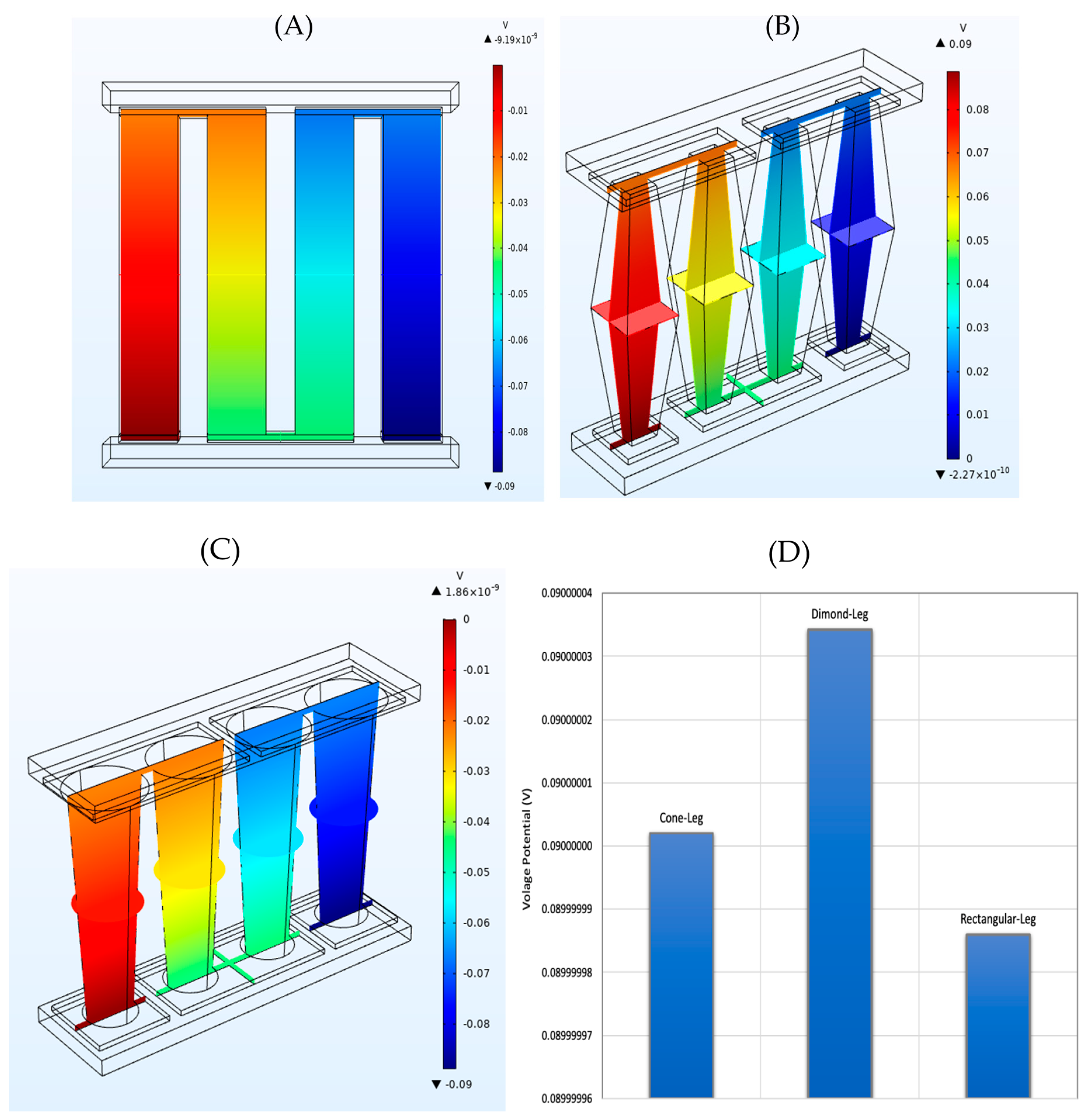
The electric potential analysis is shown in
Figure 4A–C. Thermoelectric elements are thermally connected in parallel and electrically connected in series; therefore, and as it can be seen, the voltage potential varies from one side of the models to the other end. Moreover, from
Figure 4D, it can be clearly observed that both the innovative Cone-shaped TEG model and the Diamond-shaped TEG model produced higher voltage potentials than the conventional Rectangular-shaped TEG. While this difference in electrical potential between different leg shapes is minor (only
, it has a significant impact as many thermoelectric instruments are operated in sequence. Therefore, the influence of the shape of the legs on the voltage of the whole TEG module built from 128 pairs was analysed.
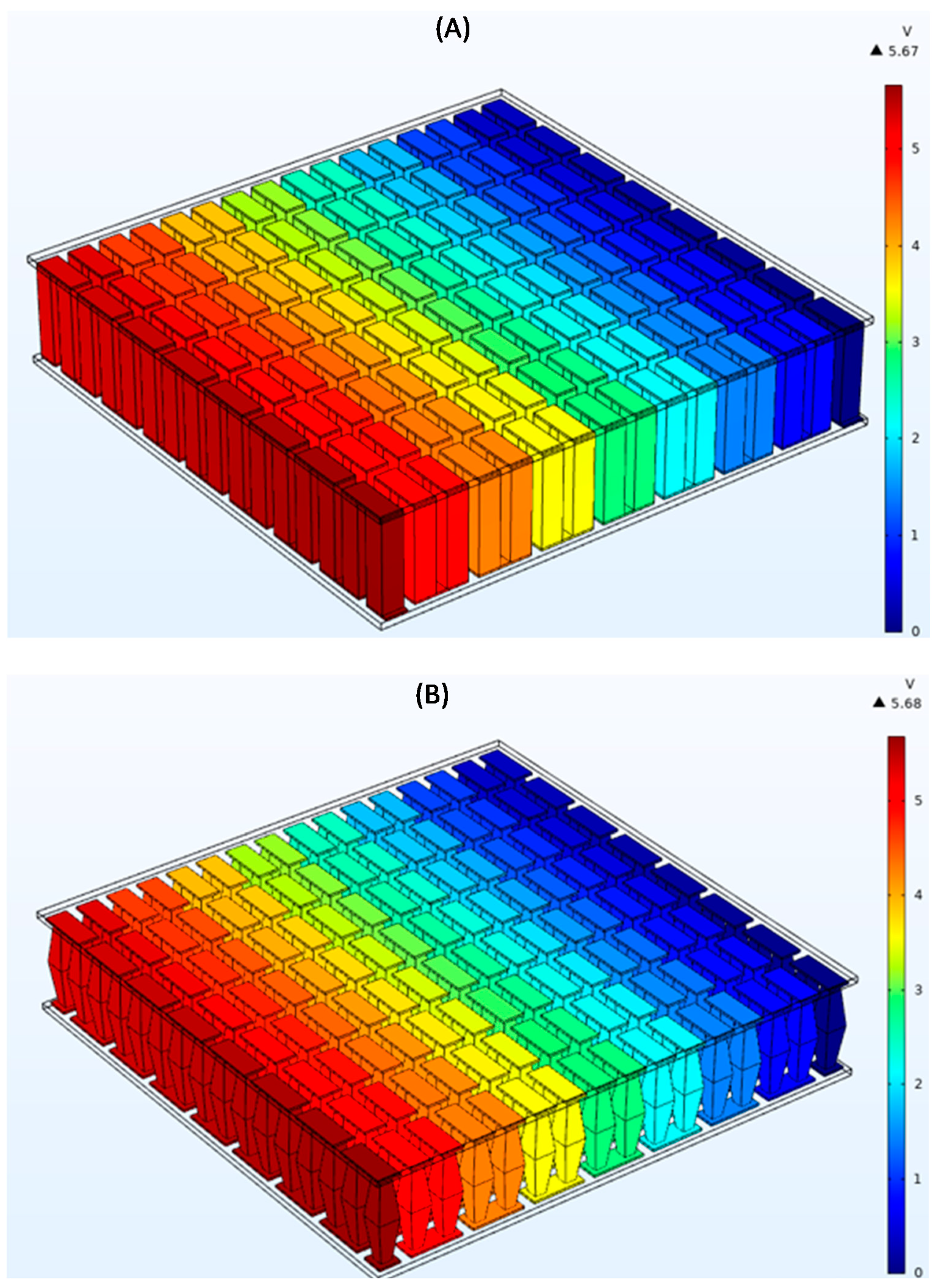
Figure 5 presents the results of the analysis carried out. The generated voltage for two pairs of Diamond leg designs was 0.09 V, and for the Rectangular design 0.089 V, for 128 pairs, theoretically it should be 5.76 V for the Diamond shape and 5.68 V for the Rectangular shape; however, the computational simulation indicated 5.68 V and 5.67 V for the Diamond and Rectangular shapes, respectively.
4.3. Thermal Stress Analysis
Thermal stress inside the device restricts the temperature difference in potential implementation because it can shorten the lifetime of the TEGs. Furthermore, material failure caused by high stress-induced cracking prevents the system from performing as intended. As a result, research into the formation and development of thermal stress in the thermoelectric system is vital [
15], particularly considering their long-term operation.
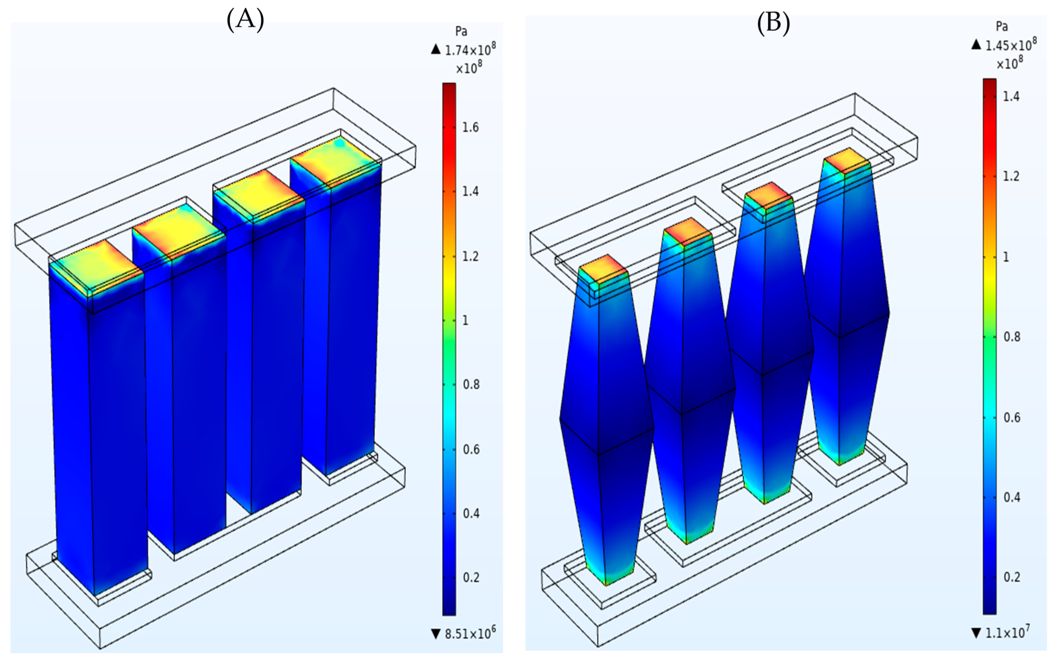
The thermal stress distribution is indicated in
Figure 6A–C. The thermal stress evaluation was achieved by relating the thermal and structural stresses to the temperatures employed at hot and cold junctions. As shown in the figure, the maximum von Mises stress appears at the hot junction side, which validates the results obtained by reference [
34]. The maximum von Mises stress for the Diamond-shaped model was noted as
which was less in comparison to the maximum von Mises stress for both the Rectangular and the Cone shapes by
.
Figure 6D was provided in order to explain the stress pattern and the von Mises distribution throughout the leg geometries. As it is demonstrated by the figure, stresses for all three models dropped sharply from the hot junction and then rose over approximately 1 mm, which is in agreement with the results obtained by [
34].
In comparing the results, the stress in the Diamond-shaped leg had two peaks at about 1 and 4 mm from the top (hot junction) and a decrease in the middle part of the model. With the Cone-shaped design, after the sharp decrease, the von Mises stress gradually increased until just before 4 mm from the hot junction where it experienced another decline. With the Rectangular shape, after the decrease at the beginning, the stress rose to , which stayed fairly constant with only a slight decline until the bottom side, where its von Mises value experienced another fall. Overall, it can be deduced that the thermal stress formed in the thermoelectric modules largely depends on the leg geometry.
The thermal stress is more developed in the area close to the hot junctions; the maximal stress occurs around the leg edges as well.
5. Conclusions
In this study, modelling and performance investigations were performed for two types of thermoelectric legs not previously analysed in the literature with geometries classified as Cone-shaped and Diamond-shaped, and the results were compared with Rectangular-shaped legs, which were selected as a reference. In the first stage of research, TEG modules built from two pairs p and n were analysed. The effect on thermal conductivity, electrical resistivity and stress analysis of the leg configuration was analysed in the various geometries using temperature dependent properties of with a numerical and computational method. The calculation was performed at fixed conditions, the hot junction was assumed to be 393 K and the cold junction was 293 K.
From the results obtained, it was observed that the temperature distribution was impacted greatly by the variable leg geometry along the leg height. For instance, the conventional Rectangular shape experienced a smoother temperature distribution compared to the Cone and Diamond shapes. In terms of the electric potential, the newly introduced Diamond shape showed the highest voltage potential in comparison to the Rectangular shape, which had the lowest voltage potential. Furthermore, at the second stage of the research, the whole module consisting of 128 pairs p and n for the two most different results was analysed. It is worth noting that the voltage for a TEG module was 5.67 V and 5.68 V for Rectangular and Diamond shapes, respectively, and the results were found to be comparable to the theoretical analysis.
Using COMSOL Multiphysics coupling features, stress analysis was performed on all the models and the hot junctions experienced the maximum stresses. The maximum von Mises stress for the Diamond-shaped model was noted as which was less in comparison to the maximum von Mises stress for both the Rectangular and the Cone shapes by Moreover, all the geometries experienced a steep decline in stress levels with distance followed by an increase in their particular values. In addition, it was observed that the Diamond shape, which experienced the least stress in comparison to the other designs, had the largest voltage potential. It should be noted that this is a preliminary study for various leg geometries, and it is only focused on steady-state processes. In a future study, the effect of a time dependent domain can be investigated through the defined approach.


