Article

Electrode with a Carbon Nanotube Array for a Proton Exchange Membrane Fuel Cell

by
Adelina A. Zasypkina
1,
Nataliya A. Ivanova
1,*,
Dmitry D. Spasov
1,2,
Ruslan M. Mensharapov
1,
Olga K. Alekseeva
1,
Ekaterina A. Vorobyeva
1,3,
Elena V. Kukueva
1 and
Vladimir N. Fateev
1
1
National Research Center “Kurchatov Institute”, 1, Akademika Kurchatova Sq., 123182 Moscow, Russia
2
Department of Chemistry and Electrochemical Energy, National Research University “Moscow Power Engineering Institute”, 14, Krasnokazarmennaya St., 111250 Moscow, Russia
3
Skobeltsyn Institute of Nuclear Physics, Lomonosov Moscow State University, 1(2), Leninskie Gory, 119991 Moscow, Russia
*
Author to whom correspondence should be addressed.
Inorganics 2023, 11(5), 219; https://doi.org/10.3390/inorganics11050219
Submission received: 23 April 2023 / Revised: 15 May 2023 / Accepted: 17 May 2023 / Published: 19 May 2023
(This article belongs to the Section Inorganic Materials)

Abstract

:
One of the most important problems in the development of proton exchange membrane fuel cells remains the selection of an efficient electrocatalyst support capable of providing a low loading of active metal with minimal changes in the electrochemical surface, electronic conductivity, and activity. In this work, carbon nanotube arrays (CNTAs) grown directly on commercial gas diffusion layers (GDLs) are used to form electrodes of a new type. The CNTAs are used in the electrode as a microporous layer. The catalytic layer is formed in the microporous layer by a method that does not destroy the carbon support structure and consists of the controlled impregnation of CNTAs with the Pt-precursor with subsequent reduction in platinum particles in the surface volume of the layer. The resulting electrode was studied by scanning/transmission electron microscopy and Raman spectroscopy. This electrode provides increased electrical conductivity of the layer and can also improve stability and longer service life due to the enhanced adhesion of carbon materials to the GDL.

1. Introduction

The global energy consumption of hydrocarbon resources is constantly increasing, which increases the burden on countries’ economies and worsens the environmental situation. The solution may be switching to highly efficient renewable energy sources, including plants with hydrogen fuel cells (FCs). However, the limited commercialization of electrochemical generators based on proton exchange membranes is explained by their relatively short service life and high cost. These problems are mainly associated with degradation processes occurring in the elements of the membrane electrode assembly (MEA) [1,2,3], including deactivation of the platinum electrocatalyst due to corrosion of the carbon support, as well as dissolution or agglomeration of Pt particles [4,5].
The high reactivity and durability of the catalytic layer (CL) largely depend on the structure of the carbon support. Due to the unique architecture of graphite, it is possible to synthesize rather complex nanomaterials on its basis, ensuring good dispersion of the catalyst on their surface and, consequently, a large electrochemical surface area (ESA). There are many different configurations of nanomaterials used as supports in fuel cells: carbon nanotubes [6] and nanofibers [7], reduced graphene oxides [8,9], graphene nanosheets [10], and other more complex structures, such as spheres and honeycombs [11,12]. Used as catalyst supports, these materials have a positive effect on FC performance and can reduce the formation of surface oxides and corrosion currents. This is explained by the fact that thinner microlayers produced from carbon nanomaterial influence the performance by increasing gas permeability, electrical conductivity, and catalytic activity [13,14,15,16] while simultaneously normalizing the water balance of the FC due to the specific packing of graphene particles, leading to the appearance of micro- and macropores [17].
The performance of an electrochemical device with a proton exchange membrane (PEM) is also greatly influenced by the formation of a CL, adhesion of the layer to the surface of the membrane/microporous electrode layer, and uniformity of their deposition. This problem can be solved by replacing the standard amorphous carbon support with a complex structured one, in particular, with carbon nanotube arrays (CNTAs) [18]. CNTAs have a developed surface, which enhances the deposition of nanometer-sized platinum particles and prevents their agglomeration, thus reducing the loading of the expensive catalyst and increasing its efficiency. The use of CNTAs in electrochemical cells also has additional advantages over other carbon structures mentioned above: surface mechanical properties, such as the modulus of elasticity and hardness, are improved [19].
CNTAs can be grown using various methods of catalytic decomposition of hydrocarbons (chemical vapor deposition—CVD). Depending on the desired CNTA shape, different CVD variations are used, such as hot filament, radiofrequency, microwave plasma-enhanced, water-assisted, thermal-enhanced, alcohol-assisted, or laser-assisted CVD [20]. In addition to the synthesis technique, the growth of CNTAs is influenced by many other factors: substrate type and material, growth catalyst used, and its deposition method [21,22]. The problem of selecting the CNT growth catalysts and optimizing the CNT synthesis was solved by Kudinova et al. [23]. The highly homogeneous film obtained in a magnetron sputtering (MS) unit was successfully used as a catalyst for the synthesis of CNTAs in the CVD process directly on the gas diffusion layer (GDL).
When a film of aligned CNTs is used as an FC cathode, current density and productivity increase, and electrocatalytic activity improves in comparison with a Pt/nonaligned CNT electrode [24]. Vertically aligned CNTs, together with Pt particles forming the electrodes, ensure good transmission of protons, electrons, and reactants. According to the study [25], vertically aligned CNTs grown on a stainless steel substrate coated with iron catalysts and inactive oxide allow for the creation of a novel structure, which directs gas diffusion through the CNTA with a platinum catalyst. This enhances the chemisorption of gaseous reagents and improves the performance of an FC with a PEM device. The hydrophobicity of vertically aligned CNTs prevents water condensation on the cathode, leading to the long-term stability of fuel cells with PEM, which is achieved through the ability to control aqueous reagents and gas diffusion [26]. The study [27] showed that the direct growth of vertically aligned CNTs on the stainless steel surface of a bipolar plate (BP) by the hot filament CVD method significantly improved the hydrophobic properties, antifreezing capability, electrical conductivity, and corrosion resistance of the BP. In [28], a new structure of a microporous layer (MPL) for FCs was created by direct growth of thin multiwalled vertically aligned CNTs on a commercial GDL carbon fiber substrate without hydrophobic treatment. A good electrical contact between the CNT and the substrate was ensured through the use of a three-layer Ti/Al/Fe catalyst. The thus obtained CNTAs were perpendicularly aligned along the entire length of carbon fibers and covered the surface of the GDL. The fuel cell tests demonstrated improvements in performance of up to 30% and improved stability and degradation resistance.
The use of CNTAs in fuel cells is currently being investigated and optimized due to the weak adhesion of carbon structures to the surface of GDLs and electrodes; the issue of the deposition of electrocatalysts, i.e., of reproducibility when creating electrodes based on new carbon structures, is still unresolved. In this regard, it is of interest to form an electrode of an electrochemical device as a complex system consisting of a commercial GDL with a deposited MPL and a CL based on a CNTA. As can be seen from the literature, a number of works are aimed at the use of a CNTA both as a GDL and an MPL and directly as a catalytic layer. However, it is necessary to optimize the morphological and physicochemical properties of CNTAs by changing the structure of the supported catalyst film in order to create a high-quality MPL structure and to ensure minimal contamination with the growth catalyst.
In this work, we solved the problem of forming a new type of electrode by growing CNTAs directly on commercial GDLs. For this purpose, a Ni catalyst deposited on the GDL surface by MS [23] was used, which allowed growing the CNTA layer by layer to the required layer thickness. The formation of a near-surface CNTA-based catalytic layer as part of the microporous electrode layer was also carried out by methods that did not disturb the structure of the carbon support.

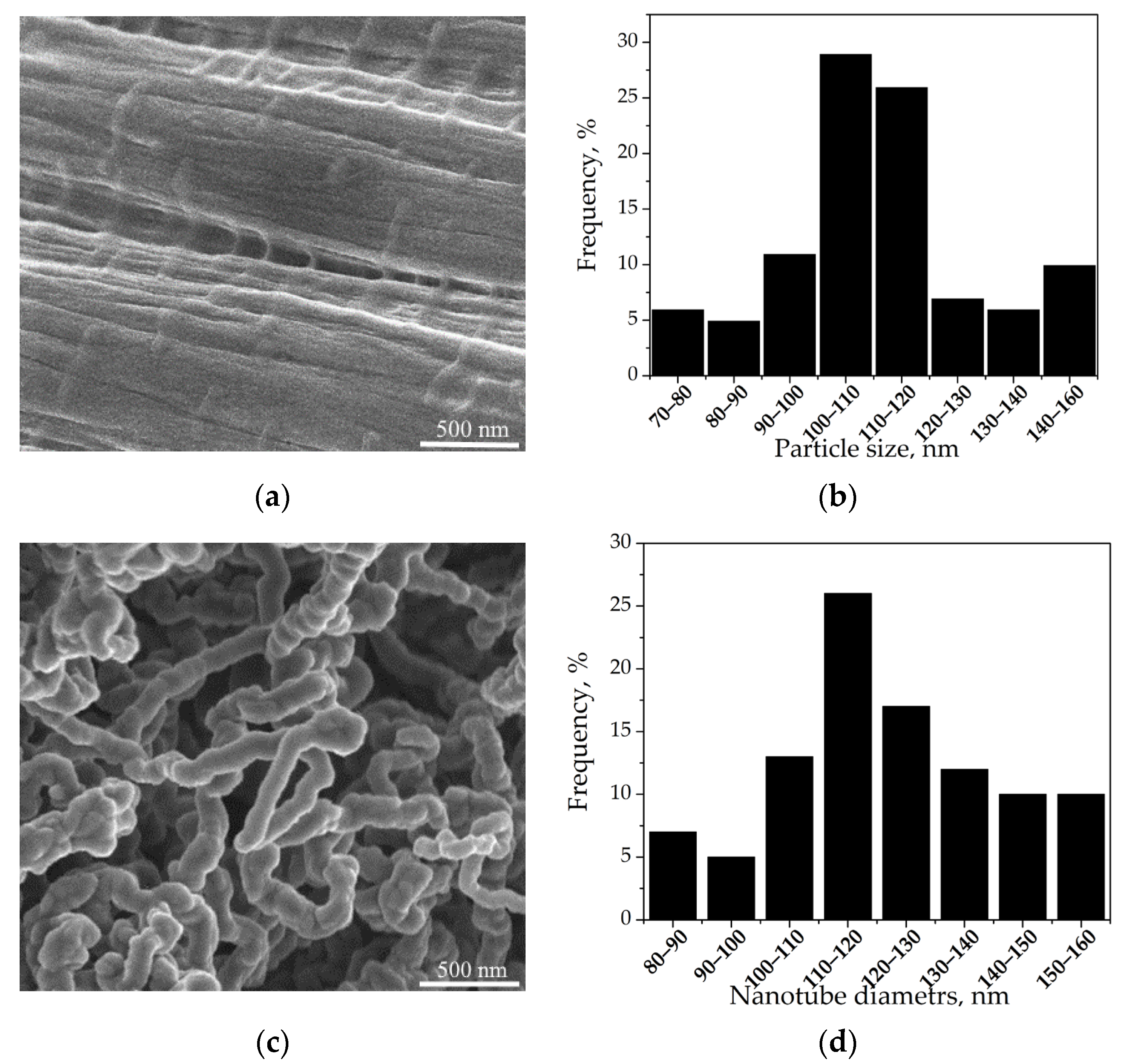
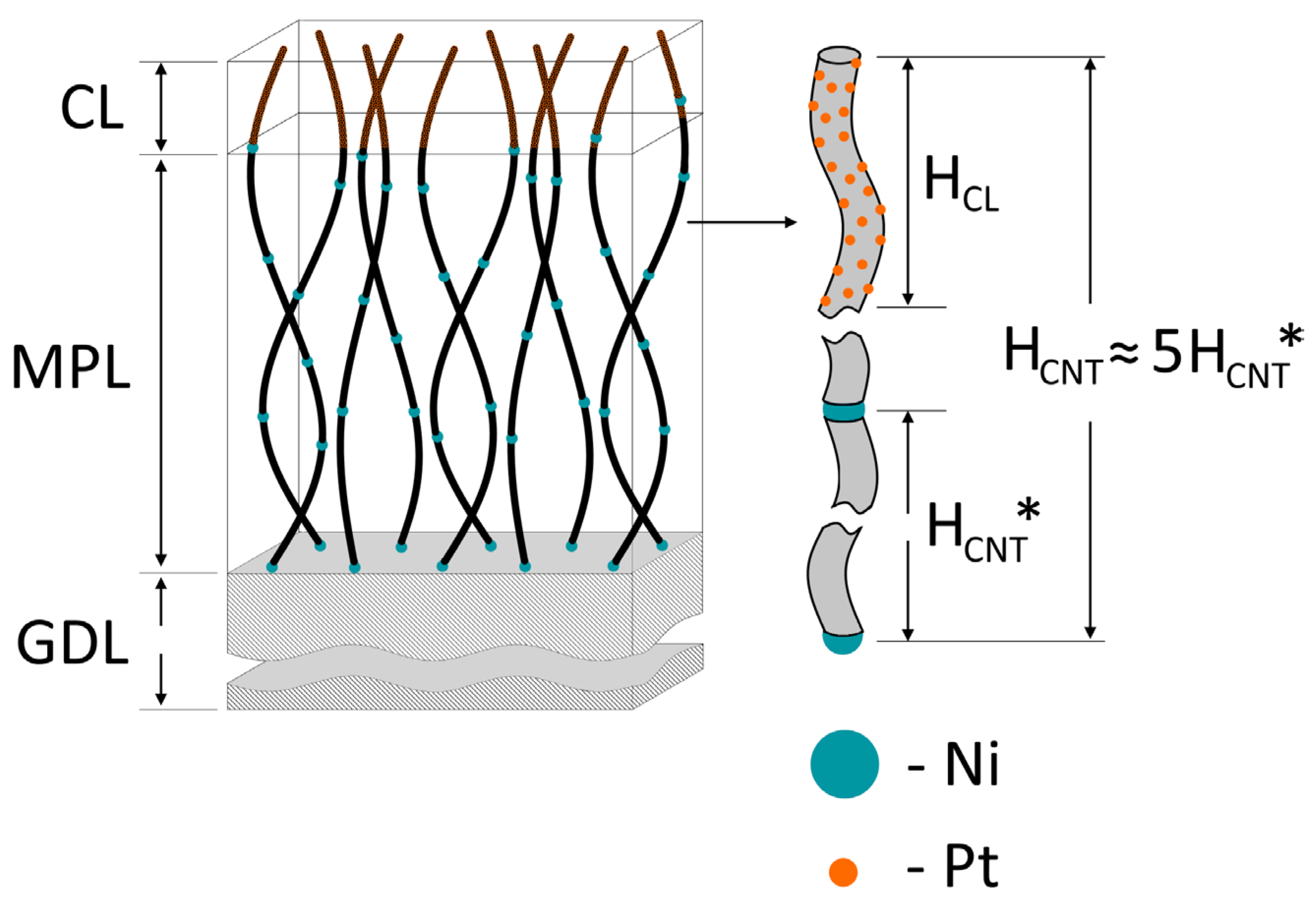
2. Results and Discussion

Characteristics of the resulting CNTA (layer thickness and tube diameter) were largely determined by parameters of the predeposited Ni catalyst (the size of agglomerates), which in turn were determined by the MS mode and sputtering duration. This phenomenon is associated, first of all, with the termination of the array growth process when the catalyst is completely carbonized [22,29].
Figure 1 shows the size distribution of the Ni particles predeposited on the GDL and outer diameters of the grown nanotubes. The distribution of the obtained nanotube diameters correlated with the particle sizes of the Ni catalyst and practically repeated the particle size distribution shape, with almost coinciding average diameter of the particles and outer diameter of the nanotubes. The long duration of the MS of the Ni catalyst (about 10 min) led to an increase in the particle size and agglomeration of the particles, as well as an increase in the unevenness of the size distribution of the agglomerates.
For nanotubes of smaller sizes, the nanotube diameter distribution was more uniform due to a more uniform distribution of catalyst particles during the MS (Figure 2). A reduction in the Ni catalyst sputtering time resulted in a more uniform nanotube diameter distribution profile. However, the CNTA thickness also decreased.
The change in the thickness of the GDL fibers with and without the grown array is shown in Figure 3. The thickness of the CNTA for the obtained samples varied and correlated with the diameter of the Ni particles.
Table 1 presents the data on the dependence of the diameter of the tubes in the obtained CNTA and the thickness of the obtained array on the diameter of the Ni catalyst particles.
The thickness of the deposited microporous layer for commercially available GDLs is about 36 μm (MPL for a hydrophobic cloth of the ELAT brand), which is 5 to 10 times greater than that of the obtained CNTAs. However, a further increase in the Ni sputtering time will lead to the agglomeration of particles into a continuous film, which will no longer act as a CNT growth catalyst. The use of layer-by-layer growth allows for increasing the array thickness. This method of layer-by-layer deposition made it possible to achieve the required CNTA layer thickness of about 27 μm in five iterations while at the same time controlling the size of the obtained nanotubes. The average nanotube diameter was about 50 nm.
Based on the measurement of the resistivity of the electrode with the MPL from the nanotube array, the electrical conductivity increased by approximately 10% compared with the commercial ELAT LT 1400 W GDL (Table 2). The layer thickness for these samples was the same—400 μm. As can be seen from the data in Table 2, at equal thickness of the electrodes, the deposited commercial carbon microporous layer with a hydrophobic component made a greater contribution to the electrode resistance compared with the deposited CNTA. The table also gives values for the ELAT LT 1400 W GDL without undercoat. The resistance of the resulting CNTA was 30% lower than that of the commercial MPL of the same thickness.
Since all GDLs represent structured carbon materials, the analysis of Raman spectra is based on the analysis of spectra of carbonaceous substances. The following two regions can be identified in the GDL spectrum: of the first (1100–1800 cm−1) and of the second (2350–3350 cm−1) order. For all samples, narrow D and G peaks of similar high intensity were observed. The shift in the G lines associated with symmetric E2g stretching and compression vibrations of C–C sp2 bonds in six-atom aromatic rings of graphene layers, from 1581 cm−1 (graphite) toward higher frequencies up to 1590–1595 cm−1, is characteristic of crystallites with a size of ~2.5 nm and less. The main contribution to the D band was made by vibrations that were specific to the six-atom aromatic rings; therefore, the D band can serve as an indicator of the presence of graphite-like nanoclusters in the carbon structure. In contrast to the D band, the G band was observed at any arrangement of carbon sp2 bonds, including all kinds of rings and chains. The spectra did not contain an additional band of “defects” D2 (1620 cm−1) in the form of a shoulder at the G peak. Nanographite is characterized by the presence of a usually very wide D3 peak (~1510 cm−1) due to the presence of interlayer defects in the structure, such as disorders in the form of amorphous carbon, which is also not characteristic of GDLs. The D4 peak (~1212 cm−1) indicated the presence of sp3 carbon bonds and was very weakly expressed. The narrowing and the increase in the intensity of the 2D peak (~2700 cm−1), which reflects the interaction between carbon layers, were associated with an increase in the crystallite size. The splitting of the band into two peaks—2D1 and 2D2—was due to the appearance of three-dimensional ordering. All considered GDLs were highly ordered carbon materials predominantly containing carbon in sp2 hybridization (long chains and rings) and forming carbon filaments, the internal structure of which is represented by graphite nanoclusters.
Analyzing the Raman spectra from ELAT LT 1400 W with and without a CNTA MPL, it can be noted that the G peak (second-order peak) was much larger in ELAT 1400 without the sublayer prior to the CNT synthesis (Figure 4), while there was no significant difference in the degree of defectiveness (based on the G/D peak intensity ratio).
Figure 5 shows SEM images of the electrode surface and the size distribution of nanotubes for the CL based on the Pt/CNTA 50 electrocatalyst. Due to the use of the method of forming the CL as part of the grown MPL based on a CNTA, which involves the method of impregnation of the CNTA with the platinum precursor followed by a reduction in particles with hydrogen, which does not destroy the original structure of the substrate, the resulting CL was characterized by a highly uniform CNT distribution, the tubes were not damaged, the integrity of their structure was preserved, and the direction of the tubes relative to the horizontal surface of the electrode also had a distributed isotropic character (Figure 5).
Figure 6a shows TEM images of the platinum particles and the size distribution of platinum. The average particle size of platinum was 5.2 nm (Figure 6b). The formation of large agglomerates was observed. The increase in the size of the platinum particles was associated with the high mass fraction of platinum in the electrocatalyst [30]. This effect was observed regardless of the electrocatalyst synthesis method. The larger particles were also characteristic of the hydrogen reduction method; however, it was the hydrogen and gas-phase reduction that allowed for preserving the structure of the obtained CNTAs during the synthesis of catalytic particles. The platinum particle size reduction could be achieved by reducing the platinum content in the electrocatalyst.

3. Materials and Methods

3.1. Making an Electrode

Application of the CNTA growth catalyst. The Ni catalyst was predeposited on the GDL by the MS method (MIR-1 facility, National Research Center “Kurchatov Institute”, Moscow, Russia) in the direct current mode with a bias voltage applied to the substrate [31]. Ni particles served as catalytic sites for nanotube growth. The Ni target thickness was 2 mm, and its diameter was 75 mm. The spraying time was from 2 to 10 min, and the Ni coating density was 0.05–0.20 mg/cm2, respectively.

3.2. Growing a CNTA

CNTAs were grown directly on commercial GDLs (hydrophobic carbon cloth of the ELAT LT 1400 brand without a microporous layer) by the CVD method (pyrolytic gas-phase deposition facility at Lomonosov Moscow State University, Moscow, Russia [32]). The synthesis procedure is described in detail in [23]. The CNT synthesis time for all samples was 30 min. The CNTA growth was stopped when the predeposited Ni catalyst was completely carburized [22]. Samples were obtained with a CNTA as an MPL with tube diameters of 40, 50, 75, and 120 nm named CNTA 40, CNTA 50, CNTA 75, and CNTA 120, respectively.
An important characteristic of the resulting array was its thickness. Since the CNTA acted both as a carrier of catalytic particles and as a microporous layer, it needed to have sufficient thickness. As shown in Figure 7a, the growth of the CNTA led to an increase in the diameter of carbon fibers of the initial GDL, which was used to judge the thickness of the CNTA layer on the GDL surface.
The CNTA thickness may increase with increasing particle size of the Ni catalyst; however, in this case, the purity and quality of the synthesized tubes decreased, and their diameter also increased [33]. Therefore, sufficient thickness of the layer was ensured by depositing an additional Ni catalyst layer on the synthesized CNTA. Thus, the array was formed layer by layer, as shown schematically in Figure 7b.

3.3. Growing a Catalytic Layer

The deposition of platinum particles was carried out by impregnation with an aqueous solution of the precursor (H2PtCl6) of a specified concentration of platinum (0.6 mg/mL) and subsequent reduction with gaseous hydrogen [34]. The impregnation was carried out by spraying the solution with an airbrush onto the surface of the CNTA layer preliminarily grown on the surface of the hydrophobized GDL. The reduction of platinum from hexachloroplatinic acid in a hydrogen flow was carried out in two stages. In the first stage, the support was dried and cleaned in an argon flow for 12 h; the reactor temperature was 120 °C, the inlet gas temperature was 25 °C, and the relative humidity was not more than 20%. In the second stage, the platinum reduction was carried out in a stream of humidified hydrogen for 12 h. Hydrogen was humidified by bubbling through the water column in a saturation tank at 50 °C. The hydrogen flow was 0.2–0.5 L/min. The platinum content in the CNTA layer was 20 wt.% at a coating density of 0.3 mg/cm2. A Pt/CNTA 50 sample was synthesized.
As a result of the above procedure, there was formed an electrode based on a commercial GDL, with a CNTA formed on its surface, acting as an MPL and a support of the Pt/CNTA electrocatalyst. The schematic diagram of the resulting electrode is shown in Figure 8.

3.4. Electrode Studies

The layer thickness was calculated on the assumption that the growth of tubes is uniform over the entire surface of the sample, as schematically shown in Figure 7a. Since it clearly distinguishes only the diameters of the original fiber and the diameters with CNTs synthesized on it in SEM images, using the approximation of the uniform growth of the CNTA, the thickness of the array (one-step growth) was calculated using the following formula:
H CNT * = D d 2
where d is the diameter of the initial fiber, D is the diameter of the fiber with the CNTA, and HCNT* is the thickness of the one-step growth CNTA layer (see Figure 7a).
The samples were examined by scanning electron microscopy (SEM) using a Versa 3D DualBeam instrument (FEI, Hillsboro, OR, USA) and a Titan 80-300 S/TEM (FEI, Hillsboro, OR, USA) transmission electron microscope (TEM).
The images obtained by SEM were processed using the ImageJ program with preliminary generation of particle contours in a graphical editor (for Pt catalyst particles). To obtain reliable data, several micrographs with different magnifications were processed, providing a total sample size of at least 100 particles.
A series of experimental Raman spectra from carbon nanotubes were obtained using the INTEGRA Spektra Probe NanoLaboratory with a SOLAR TII spectrometer (Moscow, Russia).
The specific longitudinal electrical resistance was measured in a cell consisting of a holder, electrodes, and a bar used to press the sample against the electrodes. The measurements were carried out using a CorrTest CS350 potentiostat (CorrTest Instruments, Wuhan, China). The EIS method was used for the measurement, and the values were recorded using an open potential. Detailed information is described in [35].
The specific longitudinal electrical resistance R expressed in Ohm∙µm was calculated by the formula:
R = Z · h · δ L
where Z is the measured value of the sample resistance, Ohm; h is the sample width, cm; δ is the sample thickness, µm; and L is the distance between the inner electrodes that corresponds to the sample length, cm.

4. Conclusions

Thus, there was created a new type of electrode for PEMFC that uses a CNTA as a microporous layer. The CNTAs were grown by the CVD method directly on a gas diffusion layer representing a hydrophobized carbon cloth. Ni was used as a growth catalyst, which was deposited using a magnetron sputtering facility in a constant current mode with a bias voltage applied to the substrate. The size (diameter) of the obtained CNTs correlated with the size of the Ni particles and practically repeated it. To increase the layer thickness, as well as to preserve the quality of the nanotubes in the absence of contamination by the Ni catalyst, the carbon nanotubes were grown layer by layer. Deposition of platinum catalyst particles was carried out by a nondestructive method of impregnation of CNTAs with a precursor and subsequent reduction to metal particles using hydrogen gas.
The resulting electrode demonstrated electrical conductivity that was 10% higher compared with commercial MPLs. Raman spectroscopy showed that this CNTA synthesis method has practically no effect on electrode defectiveness. The optimal CNTA thickness at a nonpolluting MPL amount of Ni was formed to 27 µm with preservation of the array structure for the tube diameter of 50 nm, suitable for uniform deposition of platinum particles without loss of their catalytic activity. The average particle size of the Pt/CNTA 50 catalyst was 5.2 nm.
Formed MPL provides increased electrical conductivity of the layer by controlling its porosity and gas permeability. The enhanced adhesion of CNTAs on the GDL increases durability at a reduced platinum content, achieved by increasing the dispersion and ESA of the platinum catalyst supported on the CNTA.

Author Contributions

Conceptualization, A.A.Z., N.A.I., R.M.M., D.D.S. and V.N.F.; methodology, O.K.A., E.V.K. and E.A.V.; software, R.M.M. and D.D.S.; validation, N.A.I. and V.N.F.; investigation, R.M.M., D.D.S., N.A.I. and A.A.Z.; resources, V.N.F.; writing—original draft preparation, A.A.Z. and N.A.I.; writing—review and editing, R.M.M., N.A.I. and D.D.S.; visualization, D.D.S., A.A.Z., N.A.I. and R.M.M.; supervision, V.N.F.; project administration, V.N.F. and N.A.I.; funding acquisition, V.N.F. All authors have read and agreed to the published version of the manuscript.

Funding

The work was carried out at the National Research Center “Kurchatov Institute” in the framework of the execution of Order No. 89 dated 20 January 2023, item 3p.2.5. “Development of new electrocatalytic materials with improved properties for PEM electrochemical devices”.

Data Availability Statement

Not applicable.

Conflicts of Interest

The authors declare no conflict of interest.

References

  1. Okonkwo, P.C.; Emori, W.; Uzoma, P.C.; Mansir, I.B.; Radwan, A.B.; Ige, O.O.; Abdullah, A.M. A Review of Bipolar Plates Materials and Graphene Coating Degradation Mechanism in Proton Exchange Membrane Fuel Cell. Int. J. Energy Res. 2022, 46, 3766–3781. [Google Scholar] [CrossRef]
  2. Okonkwo, P.C.; Ben Belgacem, I.; Emori, W.; Uzoma, P.C. Nafion Degradation Mechanisms in Proton Exchange Membrane Fuel Cell (PEMFC) System: A Review. Int. J. Hydrogen Energy 2021, 46, 27956–27973. [Google Scholar] [CrossRef]
  3. Prokop, M.; Drakselova, M.; Bouzek, K. Review of the Experimental Study and Prediction of Pt-Based Catalyst Degradation during PEM Fuel Cell Operation. Curr. Opin. Electrochem. 2020, 20, 20–27. [Google Scholar] [CrossRef]
  4. Speder, J.; Zana, A.; Spanos, I.; Kirkensgaard, J.J.K.; Mortensen, K.; Hanzlik, M.; Arenz, M. Comparative Degradation Study of Carbon Supported Proton Exchange Membrane Fuel Cell Electrocatalysts—The Influence of the Platinum to Carbon Ratio on the Degradation Rate. J. Power Source 2014, 261, 14–22. [Google Scholar] [CrossRef]
  5. Okonkwo, P.C.; Ige, O.O.; Barhoumi, E.M.; Uzoma, P.C.; Emori, W.; Benamor, A.; Abdullah, A.M. Platinum Degradation Mechanisms in Proton Exchange Membrane Fuel Cell (PEMFC) System: A Review. Int. J. Hydrogen Energy 2021, 46, 15850–15865. [Google Scholar] [CrossRef]
  6. Gupta, C.; Maheshwari, P.H.; Sasikala, S.; Mathur, R.B. Processing of Pristine Carbon Nanotube Supported Platinum as Catalyst for PEM Fuel Cell. Mater. Renew. Sustain. Energy 2014, 3, 36. [Google Scholar] [CrossRef]
  7. Sandström, R.; Ekspong, J.; Annamalai, A.; Sharifi, T.; Klechikov, A.; Wågberg, T. Fabrication of Microporous Layer-Free Hierarchical Gas Diffusion Electrode as a Low Pt-Loading PEMFC Cathode by Direct Growth of Helical Carbon Nanofibers. RSC Adv. 2018, 8, 41566–41574. [Google Scholar] [CrossRef]
  8. Kozlova, M.; Butrim, S.; Solovyev, M.; Pushkarev, A.; Pushkareva, I.; Kalinichenko, V.; Akelkina, S.; Grigoriev, S. Structural and Electrochemical Characteristics of Platinum Nanoparticles Supported on Various Carbon Carriers. C 2022, 8, 14. [Google Scholar] [CrossRef]
  9. Farooqui, U.R.; Ahmad, A.L.; Hamid, N.A. Graphene Oxide: A Promising Membrane Material for Fuel Cells. Renew. Sustain. Energy Rev. 2018, 82, 714–733. [Google Scholar] [CrossRef]
  10. Voznyakovskii, A.; Vozniakovskii, A.; Kidalov, S. New Way of Synthesis of Few-Layer Graphene Nanosheets by the Self Propagating High-Temperature Synthesis Method from Biopolymers. Nanomaterials 2022, 12, 657. [Google Scholar] [CrossRef]
  11. Fu, X.; Hassan, F.M.; Zamani, P.; Jiang, G.; Higgins, D.C.; Choi, J.Y.; Wang, X.; Xu, P.; Liu, Y.; Chen, Z. Engineered Architecture of Nitrogenous Graphene Encapsulating Porous Carbon with Nano-Channel Reactors Enhancing the PEM Fuel Cell Performance. Nano Energy 2017, 42, 249–256. [Google Scholar] [CrossRef]
  12. Wang, F.; Chen, L.; Li, H.; Duan, G.; He, S.; Zhang, L.; Zhang, G.; Zhou, Z.; Jiang, S. N-Doped Honeycomb-like Porous Carbon towards High-Performance Supercapacitor. Chin. Chem. Lett. 2020, 31, 1986–1990. [Google Scholar] [CrossRef]
  13. Sharma, S.; Pollet, B.G. Support Materials for PEMFC and DMFC Electrocatalysts—A Review. J. Power Source 2012, 208, 96–119. [Google Scholar] [CrossRef]
  14. Shaari, N.; Kamarudin, S.K. Graphene in Electrocatalyst and Proton Conductiong Membrane in Fuel Cell Applications: An Overview. Renew. Sustain. Energy Rev. 2017, 69, 862–870. [Google Scholar] [CrossRef]
  15. Hsieh, C.-T.; Wei, J.-M.; Lin, J.-S.; Chen, W.-Y. Pulse Electrodeposition of Pt Nanocatalysts on Graphene-Based Electrodes for Proton Exchange Membrane Fuel Cells. Catal. Commun. 2011, 16, 220–224. [Google Scholar] [CrossRef]
  16. Remy, E.; Thomas, Y.R.J.; Guetaz, L.; Fouda-Onana, F.; Jacques, P.A.; Heitzmann, M. Optimization and Tunability of 2d Graphene and 1d Carbon Nanotube Electrocatalysts Structure for Pem Fuel Cells. Catalysts 2018, 8, 377. [Google Scholar] [CrossRef]
  17. Mariani, M.; Latorrata, S.; Patrignani, S.; Gallo Stampino, P.; Dotelli, G. Characterization of Novel Graphene-Based Microporous Layers for Polymer Electrolyte Membrane Fuel Cells Operating under Low Humidity and High Temperature. Int. J. Hydrogen Energy 2020, 45, 7046–7058. [Google Scholar] [CrossRef]
  18. Ageev, O.A.; Blinov, Y.F.; Il’ina, M.V.; Il’in, O.I.; Smirnov, V.A.; Tsukanova, O.G. Study of Adhesion of Vertically Aligned Carbon Nanotubes to a Substrate by Atomic-Force Microscopy. Phys. Solid State 2016, 58, 309–314. [Google Scholar] [CrossRef]
  19. Luo, C.; Xie, H.; Wang, Q.; Luo, G.; Liu, C. A Review of the Application and Performance of Carbon Nanotubes in Fuel Cells. J. Nanomater. 2015, 2015, 560392. [Google Scholar] [CrossRef]
  20. Lee, J.H.; Kim, H.S.; Yun, E.T.; Ham, S.Y.; Park, J.H.; Ahn, C.H.; Lee, S.H.; Park, H.D. Vertically Aligned Carbon Nanotube Membranes: Water Purification and Beyond. Membranes 2020, 10, 273. [Google Scholar] [CrossRef]
  21. Zanin, H.; May, P.W.; Harniman, R.L.; Risbridger, T.; Corat, E.J.; Fermin, D.J. High Surface Area Diamond-like Carbon Electrodes Grown on Vertically Aligned Carbon Nanotubes. Carbon N. Y. 2015, 82, 288–296. [Google Scholar] [CrossRef]
  22. Cho, W.; Schulz, M.; Shanov, V. Growth and Characterization of Vertically Aligned Centimeter Long CNT Arrays. Carbon N. Y. 2014, 72, 264–273. [Google Scholar] [CrossRef]
  23. Kudinova, E.S.; Vorobyeva, E.A.; Ivanova, N.A.; Tishkin, V.V.; Alekseeva, O.K. A Magnetron Sputtering Method for the Application of the Ni Catalyst for the Synthesis Process of Carbon Nanotube Arrays. Nanotechnol. Russ. 2020, 15, 715–722. [Google Scholar] [CrossRef]
  24. Meng, Q.H.; Hao, C.; Yan, B.; Yang, B.; Liu, J.; Shen, P.K.; Tian, Z.Q. High-Performance Proton Exchange Membrane Fuel Cell with Ultra-Low Loading Pt on Vertically Aligned Carbon Nanotubes as Integrated Catalyst Layer. J. Energy Chem. 2022, 71, 497–506. [Google Scholar] [CrossRef]
  25. Murata, S.; Imanishi, M.; Hasegawa, S.; Namba, R. Vertically Aligned Carbon Nanotube Electrodes for High Current Density Operating Proton Exchange Membrane Fuel Cells. J. Power Source 2014, 253, 90–97. [Google Scholar] [CrossRef]
  26. Meng, X.; Deng, X.; Zhou, L.; Hu, B.; Tan, W.; Zhou, W.; Liu, M.; Shao, Z. A Highly Ordered Hydrophilic–Hydrophobic Janus Bi-Functional Layer with Ultralow Pt Loading and Fast Gas/Water Transport for Fuel Cells. Energy Environ. Mater. 2021, 4, 126–133. [Google Scholar] [CrossRef]
  27. Lu, C.; Shi, F.; Jin, J.; Peng, X. Study on the Properties of Vertical Carbon Nanotube Films Grown on Stainless Steel Bipolar Plates. Materials 2019, 16, 899. [Google Scholar] [CrossRef]
  28. Fontana, M.; Ramos, R.; Morin, A.; Dijon, J. Direct Growth of Carbon Nanotubes Forests on Carbon Fibers to Replace Microporous Layers in Proton Exchange Membrane Fuel Cells. Carbon N. Y. 2021, 172, 762–771. [Google Scholar] [CrossRef]
  29. Lin, J.; Yang, Y.; Zhang, H.; Su, B.; Yang, Y. Optimization of CNTs Growth on TiB2-Based Composite Powders by CVD with Fe as Catalyst. Ceram. Int. 2020, 46, 3837–3843. [Google Scholar] [CrossRef]
  30. Mensharapov, R.M.; Ivanova, N.A.; Zasypkina, A.A.; Spasov, D.D.; Sinyakov, M.V.; Grigoriev, S.A.; Fateev, V.N. Model Study of CNT-Based PEMFCs’ Electrocatalytic Layers. Catalysts 2022, 12, 1227. [Google Scholar] [CrossRef]
  31. Ivanova, N.A.; Alekseeva, O.K.; Fateev, V.N.; Shapir, B.L.; Spasov, D.; Nikitin, S.M.; Presnyakov, M.Y.; Kolobylina, N.N.; Soloviev, M.A.; Mikhalev, A.I.; et al. Activity and Durability of Electrocatalytic Layers with Low Platinum Loading Prepared by Magnetron Sputtering onto Gas Diffusion Electrodes. Int. J. Hydrogen Energy 2019, 44, 29529–29536. [Google Scholar] [CrossRef]
  32. Chechenin, N.G.; Chernykh, P.N.; Vorobyeva, E.A.; Timofeev, O.S. Synthesis and Electroconductivity of Epoxy/Aligned CNTs Composites. Proc. Appl. Surf. Sci. 2013, 275, 217–221. [Google Scholar] [CrossRef]
  33. Lin, J.; Yang, Y.; Zhang, H.; Yang, Y.; Hu, S. Effects of Synthesis Temperature and Fe Catalyst Amount on the Performance of in Situ CNTs/TiB2 Composites. J. Alloys Compd. 2018, 745, 817–824. [Google Scholar] [CrossRef]
  34. Ivanova, N.A.; Spasov, D.D.; Zasypkina, A.A.; Alekseeva, O.K.; Kukueva, E.V.; Vorobyeva, E.A.; Kudinova, E.S.; Chumakov, R.G.; Millet, P.; Grigoriev, S.A. Comparison of the Performance and Durability of PEM Fuel Cells with Different Pt-Activated Microporous Layers. Int. J. Hydrogen Energy 2021, 46, 18093–18106. [Google Scholar] [CrossRef]
  35. Ivanova, N.A.; Spasov, D.D.; Grigoriev, S.A.; Kamyshinsky, R.A.; Peters, G.S.; Mensharapov, R.M.; Seregina, E.A.; Millet, P.; Fateev, V.N. On the Influence of Methanol Addition on the Performances of PEM Fuel Cells Operated at Subzero Temperatures. Int. J. Hydrogen Energy 2021, 46, 18116–18127. [Google Scholar] [CrossRef]
Figure 1. SEM image of the GDL with the Ni catalyst (a), size distribution of Ni agglomerates (b), SEM image of the grown CNTs (c), and size distribution of CNTs diameters for the CNTA 120 sample (d).
Inorganics 11 00219 g001
Figure 2. SEM images of the surface of the CNTAs and size distribution of grown nanotubes for CNTA 40 (a,b) and CNTA 75 (c,d).
Inorganics 11 00219 g002
Figure 3. SEM images of GDL carbon fibers with (a) and without (b) CNTA 40. The thickness of the array is 4 μm.
Inorganics 11 00219 g003
Figure 4. Raman spectra of ELAT LT 1400 cloth without MPL and with the grown CNTA 50.
Inorganics 11 00219 g004
Figure 5. SEM image of the electrode surface.
Inorganics 11 00219 g005
Figure 6. TEM image of the obtained Pt particles (a) and their size distribution (b) for the Pt/CNTA 50 electrocatalyst.
Inorganics 11 00219 g006
Figure 7. (a) Schematic representation of the CNTA growth on the GDL. CNTA on the fibers of the initial carbon GDL. (b) Layer-by-layer growth of the CNTA, where d is the diameter of the initial fiber, D is the diameter of the fiber with the CNTA (one-step growth), HCNT* is the one-layer (one-step growth) CNTA thickness, and HCNT is the entire CNTA thickness. Symbols: blue dots are Ni particles, gray cylinder is the GDL fiber, and black line is CNT.
Inorganics 11 00219 g007
Figure 8. Schematic of the obtained CNTA-based electrode, where particles of the Ni catalyst used for the CNT growth are marked in blue, the platinum catalyst particles are marked in red, HCL is the height of the catalytic layer, HCNT is the height of the entire microporous layer of the CNTA, and HCNT* is the height of one layer obtained by a single CNT synthesis.
Inorganics 11 00219 g008
Table 1. Dependence of the characteristics of the obtained CNTA (layer thickness and tube diameter) on the particle size of the predeposited Ni catalyst. D is the diameter of the GDL fiber with the CNTA, d is the diameter of the initial GDL fiber, HCNT* is the one-layer CNTA thickness, and HCNT* is the entire CNTA thickness.
SampleInitial GDLDiameter
(Average) of Ni Particles, nm
Diameter
(Average) of Nanotubes, nm
D, μmd, μmHCNT*, μm
(One-Step Growth)
HCNT, μm
CNTA 45ELAT LT 1400 W without a microporous layer40 ± 545 ± 517 ± 19 ± 14 ± 1-
CNTA 5050 ± 550 ± 520 ± 15 ± 127 ± 2
CNTA 7570 ± 575 ± 522 ± 16 ± 1-
CNTA 120110 ± 10120 ± 1025 ± 18 ± 1-
Table 2. Results of measuring the longitudinal resistivity of GDL samples.
SampleLongitudinal Resistivity
(Ohm·µm)
Thickness
(µm)
Longitudinal Resistivity
of the MPL (Ohm·µm)
ELAT LT 1400 W330400100
ELAT LT 1400 W without MPL230370-
ELAT LT 1400 W + CNTA 5030040070
Disclaimer/Publisher’s Note: The statements, opinions and data contained in all publications are solely those of the individual author(s) and contributor(s) and not of MDPI and/or the editor(s). MDPI and/or the editor(s) disclaim responsibility for any injury to people or property resulting from any ideas, methods, instructions or products referred to in the content.

