1. Introduction
Herein, we report the electrochemical properties and sensing of a drug molecule, 4-butyl-Ν,Ν-bis{[2-(2H-tetrazol-5-yl)biphenyl-4-yl]methyl}imidazolium bromide (BV6), an angiotensin II receptor blocker, usually referred to as bisartans. This work is in the realm of exploring electrochemical methods for drug detection [
1]. Furthermore, similar efforts were used for the detection of a similar compound, losartan, the first oral non-peptide mimetic of angiotensin II hypertension medicine [
2]. It is expected that the sensing electrodes used for this molecule could be applied for other structurally similar molecular drugs, whilst the choice of BV6 is based on its proposed applicability in disease prevention. Electrochemical techniques such as voltammetry and potentiometry enable quick drug detection in biological fluids, pills, or suspensions and ensure drug quality and dose. These methods offer specificity, high sensitivity, low detection limits in the μM/nM range, the possibility of real-time results, ease of preparation and operation, and cost-effectiveness when compared with other analytical methods used for drug detection [
3,
4].
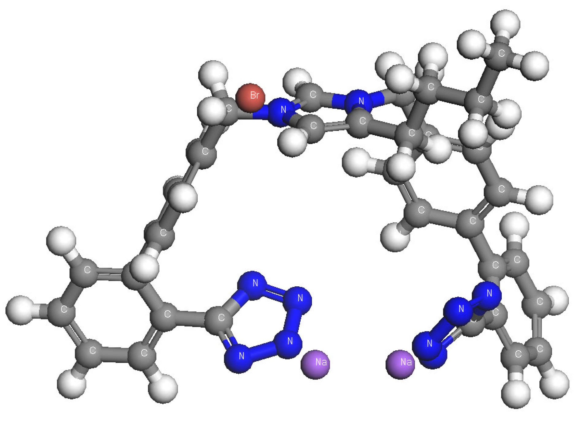
As illustrated in
Scheme 1, the structure of BV6 consists of two biphenyl moieties (either ortho-substituted tetrazole or carboxylate) at the N-1 and N-3 nitrogens of imidazole. Bisartans regulate the components of the renin angiotensin system, a prime target for cardiovascular disease therapy. According to the literature, in in-silico studies, these appear to strongly bind to the SARS-CoV-2 RBD/ACE2 complex spike [
5,
6,
7,
8,
9,
10,
11].
The materials that have been used for the fabrication of electrodes for drug determination exhibit a large variety of electrical and electronic properties. In this work, naturally formed hybrid organic–inorganic semiconductors (HOISs), also named as short perovskite materials [
12], have been selected as they exhibit enhanced quantum and dielectric confinement of their direct band gap excitons, as well as high mobility and diffusion lengths for their electrons and holes.
In general, HOISs form low-dimensional semiconducting structures, whose dimensionality strongly depends on the starting stoichiometry and precursor selection. The dimensionality refers to that of the active semiconducting inorganic network—usually a metal halide; this last network can take a range of dimensionalities from 0D up to 3D. The dimensionality also depends on the choice of the organic part content. Such networks are shown in
Scheme 2, spanning from two-dimensional up to three-dimensional cases; 2D, left (n = 1), to 3D, right (n = ∞) [
13]. The enhanced mobility of the charged carriers, i.e., electrons and holes, as well as their increased diffusion length, allows HOISs to serve as sensors [
14], photovoltaics [
15], light-emitting diodes [
16,
17,
18,
19], and chemielectroluminescent materials. Additionally, their cost and fabrication simplicity places them as suitable for use as electrode materials. Also, their inherent optical absorption (OA) and photoluminescence (PL) excitonic peaks are strong and tunable by chemistry, as has already been evidenced by numerous publications [
20,
21]. Also, the excitons in HOISs are distinct electronic states at room temperature, including the perovskite used in this work. The aforementioned improved optical and electronic properties of HOISs, as well as their flexible nature, allows them to be used in novel devices. However, a unique disadvantage these materials exhibit is that they are usually degraded by water; thus, organic solvents have been used in the present study.
Graphite paste/silica (G–SiO
2) film electrodes, present great advantages as opposed to standard carbon electrodes (glassy or metallic) and their use in electrochemical studies is constantly increasing [
3,
22]. Previous studies have shown that they exhibit high conductivity, high electrocatalytic activity for many redox reactions, and resistance to surface fouling. Additionally, they can remain stable in organic solvents for a relatively long time (several hours), perform at lower overpotentials, and are reusable [
23]. Adding to the aforementioned advantages, the ease of manufacturing, the lower cost, and the possibility of chemical modification make the G–SiO
2 film electrodes even more appealing [
24].
Over the last 30 years, material scientists have produced a variety of electrodes with unique electronic and structural characteristics, with the ability to mediate fast electron transfer for a wide range of electroactive compounds. These electrodes also exhibit electrocatalytic activity towards agricultural or food-related hazardous substances and pharmaceutical organic compounds and guide the development of new voltammetric and amperometric quantitative sensors [
1,
2,
4,
14,
25]. Most electrochemical methods rely on the modification of electrodes, such as the graphite paste or the glassy carbon electrodes, by nanostructure or porous materials to enhance and increase their electroactive surface area and to improve their mechanical strength and chemical stability. By using a modifier (such as conducting polymers, nanoparticles, etc.), it is possible to dramatically improve the sensitivity and selectivity of an electrode [
2,
24,
26]. Therefore, in this work, an HOIS has been synthesized and used as a modifier on the surface of a G–SiO
2 film electrode on a fluorine-doped tin oxide (FTO) glass substrate. More specifically, the perovskite has been adsorbed steadily on the surface of a G–SiO
2 film electrode for the electrochemical characterization and quantitative determination of BV6 for the first time.
2. Results and Discussion
2.1. X-ray Diffraction
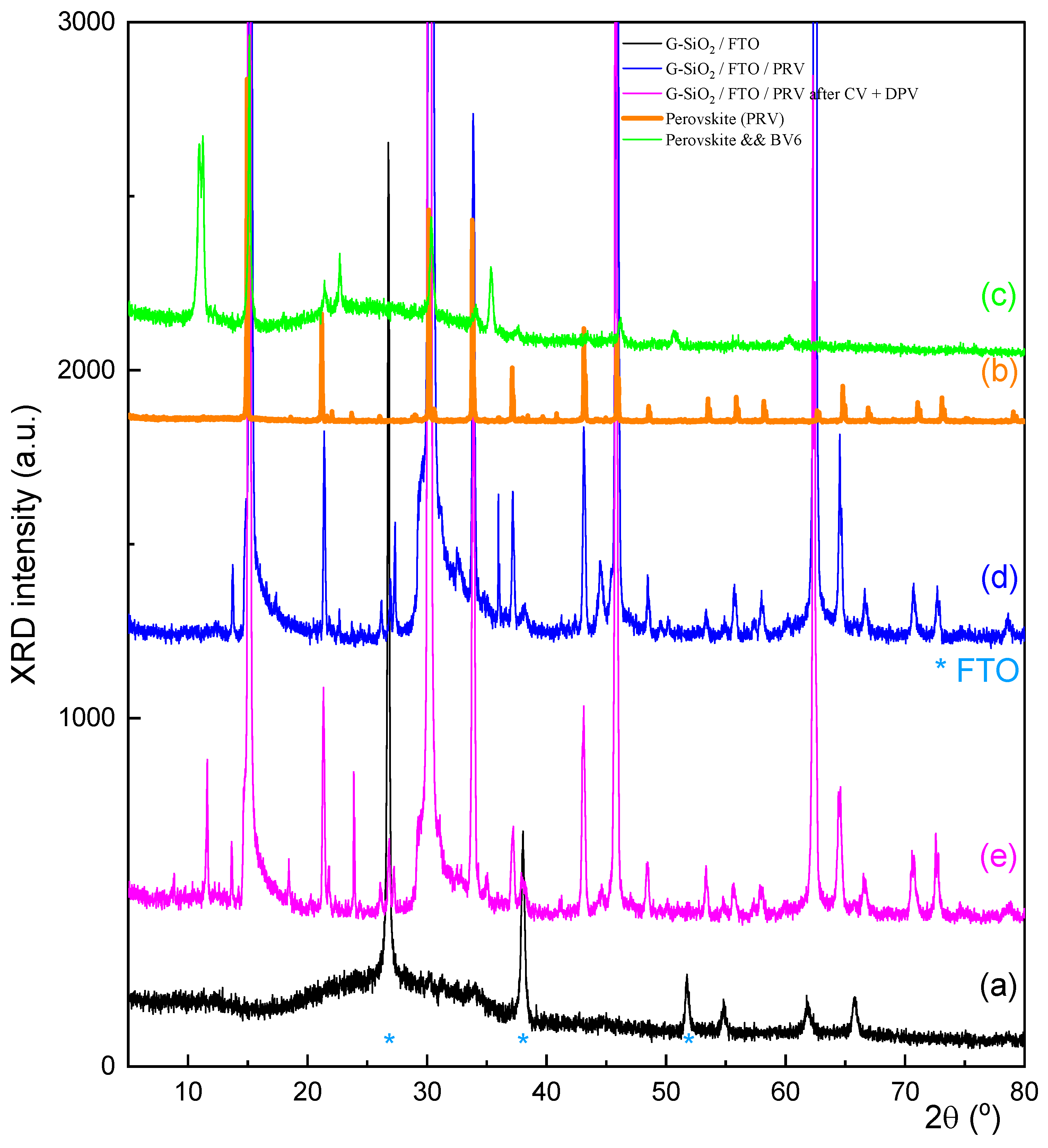
In
Figure 1, the XRD patterns of all the materials are presented. For the perovskite (
Figure 1b) employed in this work, no precursor PbBr
2-associated peaks were found in its XRD pattern, showing the complete reaction towards the final perovskite.
For the composite films (
Figure 1d), before being used for the electrochemical measurements, the characteristic peaks of the perovskite at 14.85°, 21.35°, and 30.17° on the G–SiO
2/FTO/perovskite film are observed, confirming its successful immobilization on the G–SiO
2 surface without its structure being altered in a significant manner. In this point, it is important to note that the pattern (1d) shows several small peaks at 13.69°, 27.34°, 35.96°, and 44.59° which may have arisen from recrystallization of the perovskite, involving Na
+ ions and possibly SiO
2 units on graphite. The pattern of the G–SiO
2 on the FTO glass substrate presents three slightly intense peaks at 26.54°, 38°, and 51.43° which correspond to the plane indices (110), (200), and (211) of the tetragonal SnO
2 structure due to the FTO glass slide. Smaller peaks which correspond to the plane indices (101), (220), (310), and (301) also confirm the previous pattern. The amorphous character of the G–SiO
2 on FTO is only presented as a broad peak (
Figure 1a) centered at about 26°. After the cyclic voltammetric measurements, the XRD pattern of the used composite material exhibited the peaks of the perovskite, as well as a double peak at 11.63° and a single peak at 35.33°. To determine the origin of these peaks, which could be due to some reaction or degradation of the perovskite, another pattern (
Figure 1c) has been added. It corresponds to a reaction of the perovskite and BV6 after being dissolved in DMF, while this time BV6 has a much greater concentration than the one used in the sensing experiments. Thus, it is concluded that the peaks at low angles may be due to the formation of low-dimensional perovskites. This will become more evident in the optical measurements as depicted later on.
In effect, it is safe to assume that the perovskite remains mostly intact during the electrochemical measurements, while only a small part of it is consumed by its embedding in the amorphous matrix, as well as due to its electrochemical interaction with the BV6. As will be discussed later, the optical properties, especially the UV absorption spectra, related to the band gap and exciton remain intact after usage. It is interesting that BV6 can alter the perovskite’s structure, most probably due to the presence of the bromine in its structure, or in general its halogen content, which probably allows BV6 to intercalate within PbBr
x layers, giving rise to the low angle peak (
Figure 1c), which differs though by 0.6° from that exhibited from the low angle peak of the used sample (
Figure 1e). Due to the complexity of the XRD patterns’ peaks among the samples that have interacted with BV6, it is conjectured that any electrochemical redox reaction leads to new BV6/perovskite complexes which under the applied oxidation potential give rise to electrochemical peaks; this is conjectured to take place by donating redox-generated electrons while any by-products revert to the original perovskite structure.
2.2. SEM Imaging of Surface Topography
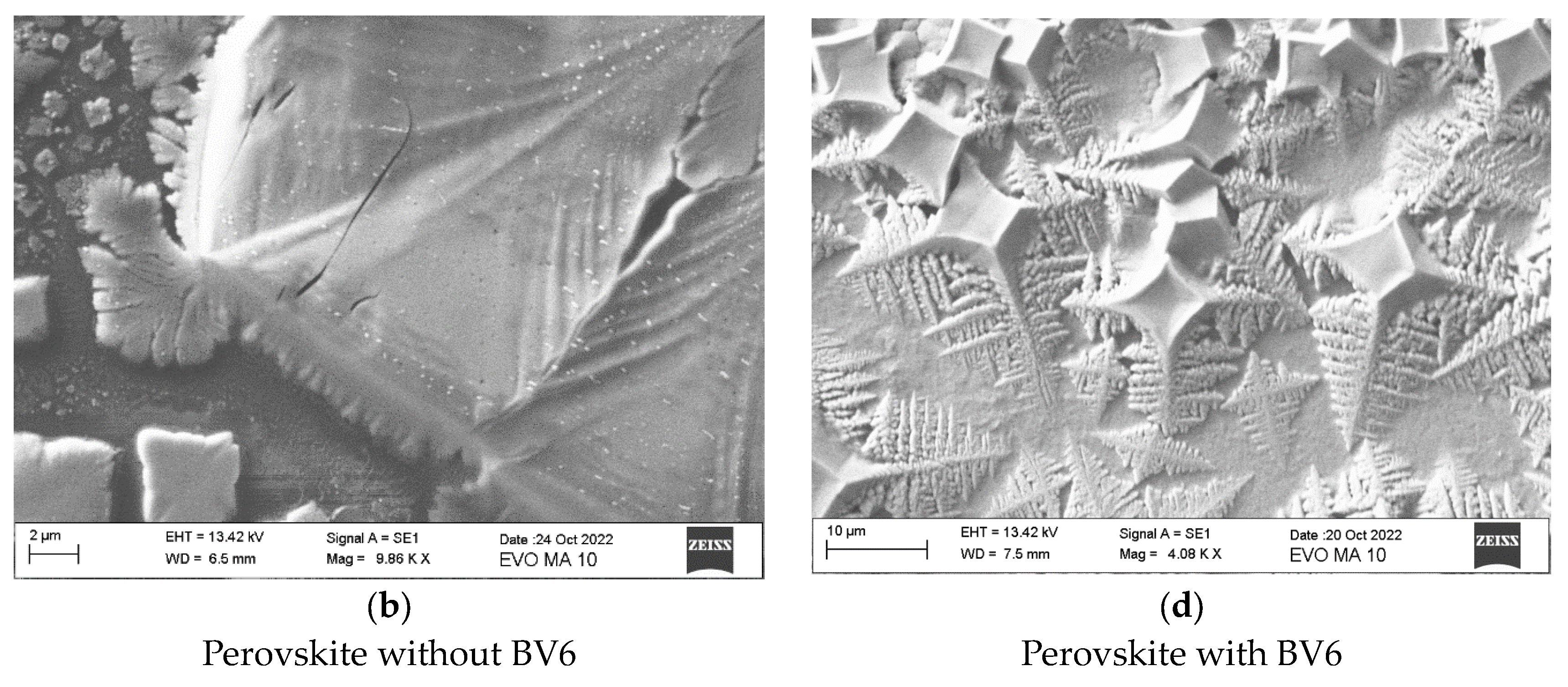
To evaluate the perovskite/G–SiO2 films on FTO glass slides, before and after the immobilization of the perovskite on their surface, scanning electron microscopy (SEM)/energy-dispersive X-ray (EDX) was also used. The same technique was used to examine any modification on the surface of the films after the cyclic voltammetry (CV) measurements and after the additions of BV6 concentrations in the organic electrolyte solution. This allows us to monitor if the applied biases or the BV6 concentration could alter the morphology, stoichiometry, and structure of the immobilized perovskite.
Figure 2a,b show the SEM images of the perovskite before its immobilization on the G–SiO
2/FTO films. After the reaction of BV6 with perovskite, as depicted in
Figure 2c,d, the formation of a cube-like structure was observed at the center of the grains of the perovskite, while away from the fractal-like and cuboid structure no Pb was detected, implying the existence of BV6. The fractal-like growth is possibly linked to the planar form of the BV6 molecule and its capability to carry charge of different polarity in different regions, leading to the formation of some new perovskite phases or shapes.
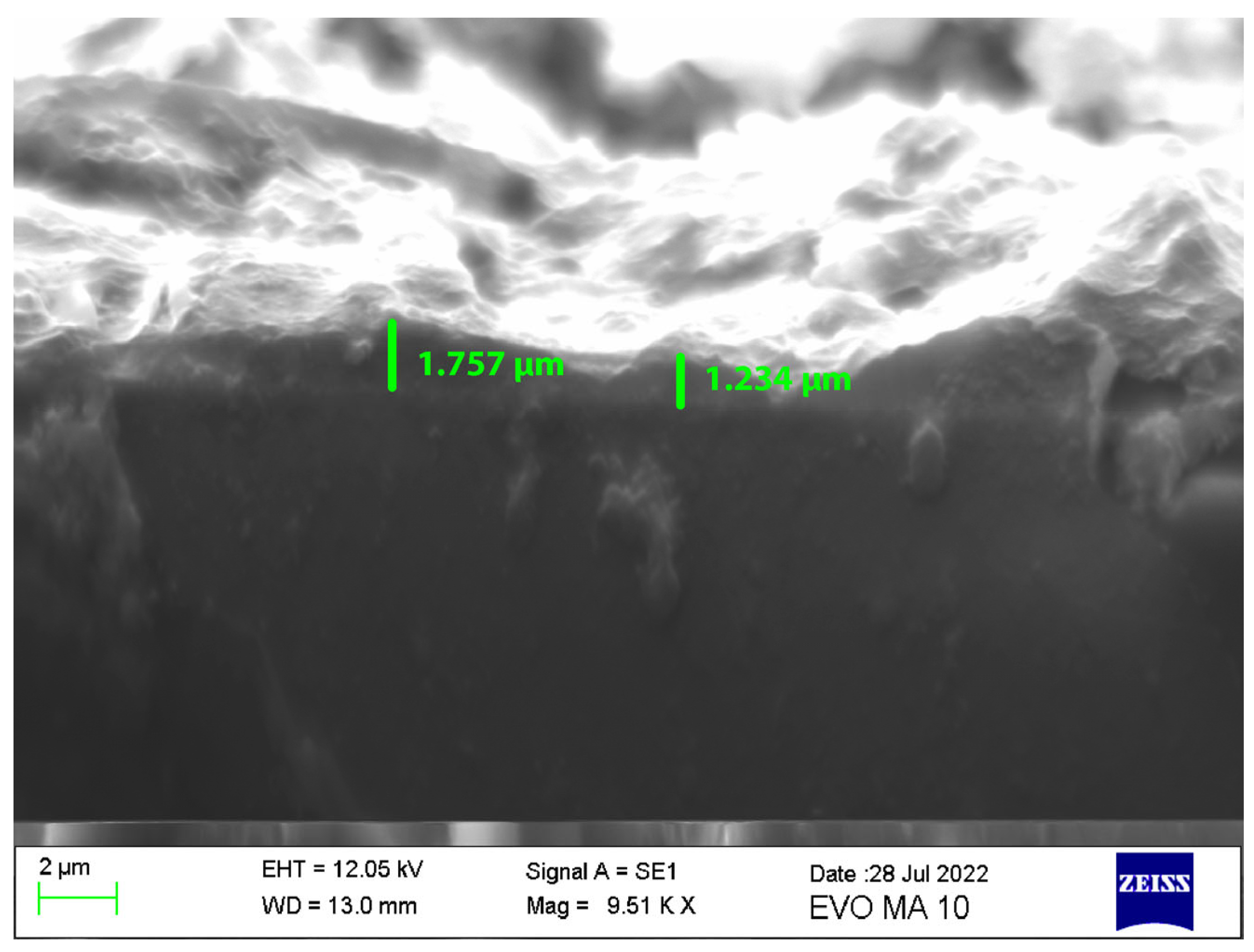
The addition of perovskite in the G–SiO
2 paste exhibits a homogenous nanostructure with a high effective surface consisting of visually numerous wrinkles and a highly rough surface, in favor of high perovskite loading and the introduction of multiple potential electroactive sites that provide a clear advantage for the sensing of BV6. Such an image acquired before the electrochemical measurements is shown in
Figure 3 (cross section), while
Figure 4 shows the images of the film before and after the electrochemical measurements.
Figure 3 shows that the top active film has a thickness of about 1–2 μm, which is of the same scale as the perovskite crystallites retained on top of the film.
Finally, the SEM images for the electrodes’ surface, after their usage for the electrochemical measurements, are shown in
Figure 4. EDX elemental analysis for the atomic stoichiometry of Pb:Br shows that the observed cuboidal form of the 3D perovskite is at a ratio in excess of 3, even up to 3.5, depending on the region of the surface, verifying the existence of the 3D perovskite form instead of any PbBr
2 by-products, which would have a ratio of 2.
2.3. Optical Measurements
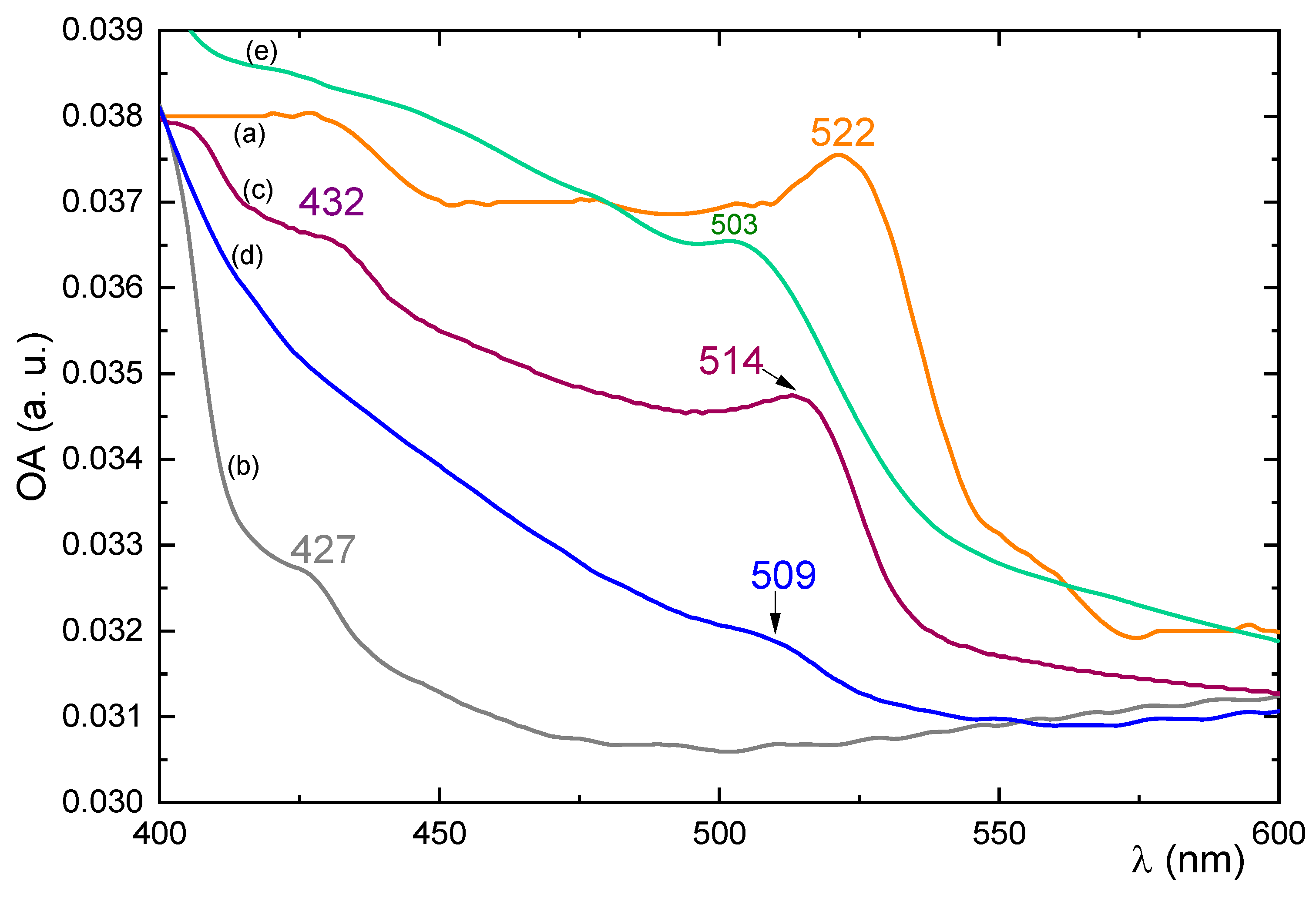
In
Figure 5, the UV–Vis optical absorption spectra of all materials used in this work are presented. The pristine perovskite (
Figure 5a) shows an energy band gap along with its accompanying exciton absorption peak at 522 nm, where both are convoluted, in accordance with previous works [
20]. BV6 shows no absorption peaks in the region of interest (
Figure 5b). Before the use of the composite electrode for sensing BV6, the combined G–SiO
2/perovskite optical absorption peak appears to shift to lower wavelengths (
Figure 5d), ca. 509 nm, probably due to some low dimensional species that have been afforded by the perovskite growth within the spaces afforded by the amorphous paste. After the electrochemical measurements (
Figure 5e), the peak further blue shifts towards 503 nm. Similarly, in order to further investigate the experiments performed by reacting BV6 and perovskite on a composite electrode, another similar reaction product was formed by reacting substantial quantities of BV6 with perovskites, in DMF, as a standalone material. In this case, the perovskite-BV6 product (
Figure 5c) appears to exhibit a peak at 514 nm, which again shows that BV6 can intercalate at sufficiently large quantities within the perovskite structure and yield other intermediate structures which will be reported elsewhere.
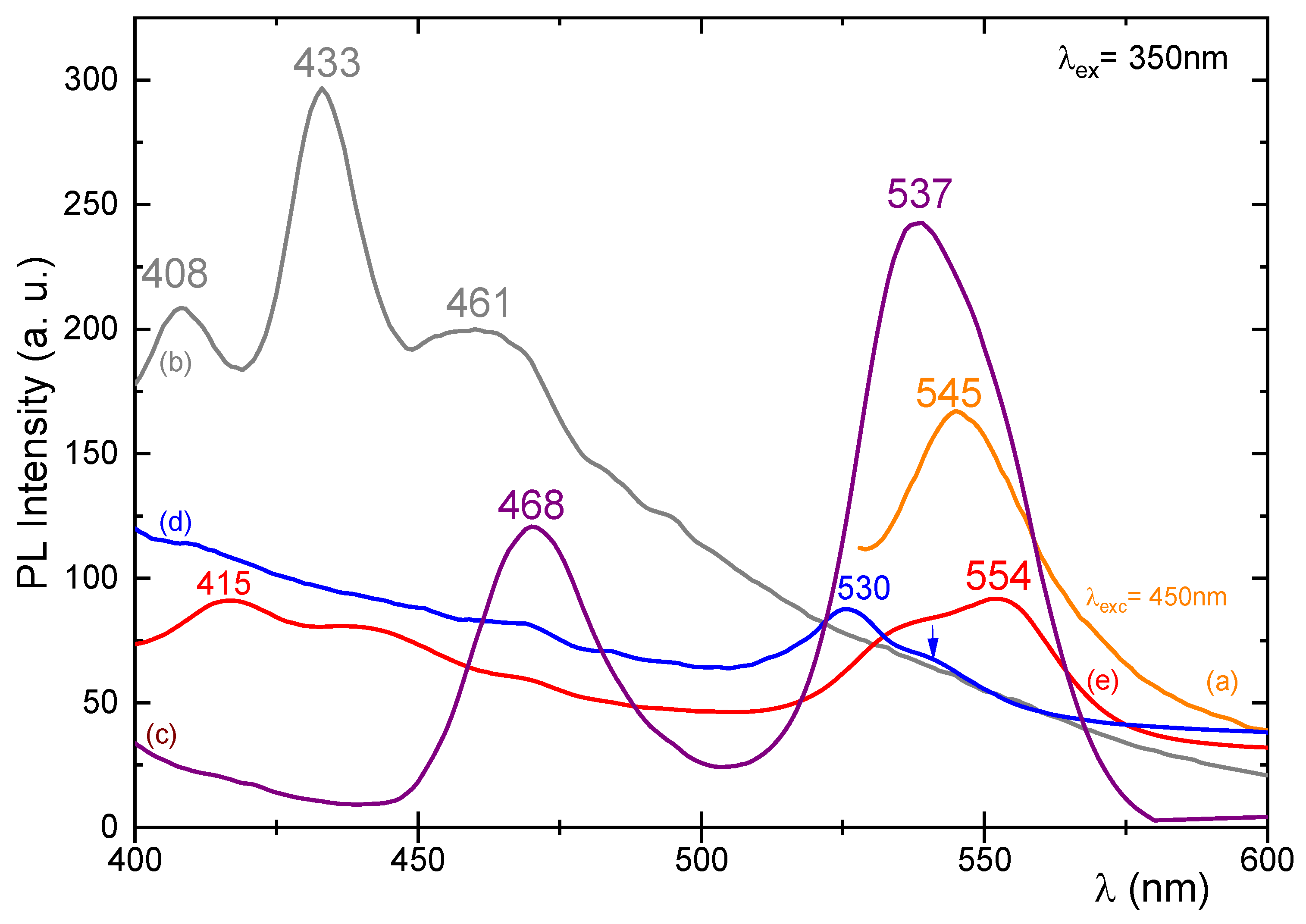
In
Figure 6, the corresponding PL spectra of the compounds are provided. The pristine perovskite shows a peak, slightly red-shifted with regard to the absorption peak, at 545 nm (
Figure 6a). BV6 shows only high-energy luminescence (
Figure 6b) when excited with 350 nm with its peaks appearing at 408, 433, and 461 nm again away from the perovskite peak and in summary has no low energy peaks.
Figure 6c shows the PL of the reaction among BV6 and perovskites when using large amounts of both perovskite and BV6, showing in accordance with the optical absorption spectra the possibility of forming low-dimensional structures, since the PL has blue-shifted with regard to the pristine perovskite compound.
Before sensing, the perovskite OA peak at 545 nm is shifted to 530 nm, see
Figure 6d, once being mixed with the G–SiO
2 paste, which corresponds to the lower peak as seen in the UV–Vis spectra. This is in accordance with the blue-shift evident in the optical absorption spectra of the perovskite/composite material, which shows some strong quantum confinement of the perovskite structures. After sensing,
Figure 6e, the peak at 415 nm corresponds to the BV6 molecule that has been absorbed by the perovskite layer, while the used electrode also exhibits an extra PL peak at 554 nm, red-shifted with regard to the pristine perovskite, possibly due to perovskite with trapped excitons and/or defects.
The used composite electrode was stored at room temperature with a 50% relative humidity for four months and underwent electrochemical sensing measurements again. Its optical properties, as determined by spectroscopic methods, are depicted in
Figure 7, which verify that after this time, the UV–Vis absorption spectrum remains intact, yet the PL signal shifts the excitonic degradation peak, at 554 nm, back to 543 and 507 nm, even after this long period. It appears as if another low-dimensional adduct has formed after this long time and a pristine 3D perovskite has recovered from the sensing experiments, with any chemical/redox reaction with BV6.
2.4. Electrochemical Behavior of Perovskite/G–SiO2/FTO Film Electrode
The electrochemical behavior of the composite perovskite/G–SiO
2/FTO film electrode was investigated by CV in DCM/TBAH electrolyte, where the perovskite appears to be stable and does not desorb from the surface of the film, as evidenced by the color of the electrolyte solution and the observation of the excitonic OA and PL peaks for the used films. The CVs of the FTO substrate and of the G–SiO
2/FTO film electrode, before and after the immobilization of the perovskite on its surface, are presented in
Figure 8. The bare film electrode exhibited a large background current and an almost rectangular CV plot without the presence of any oxidation or reduction peaks (
Figure 8b). This shape of the CV plot is expected for double-layer and pseudo-capacitive materials. Also, in
Figure 8a, the CV plot of the FTO glass substrate does not exhibit any noticeable redox response and the respective capacitive current is negligible. After the attachment of the perovskite on the surface of the G–SiO
2/FTO film electrode, the background current is higher due to the larger surface area of the modified film electrode and, in addition, a small irreversible anodic peak at +0.31 V is observed (
Figure 8c) due to the presence of the adsorbed perovskite. As shown in
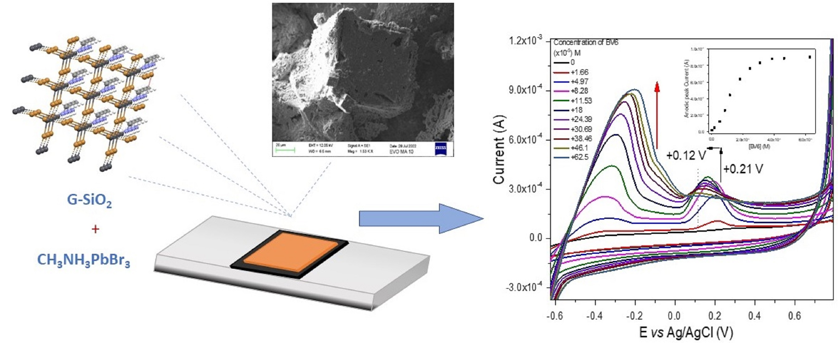
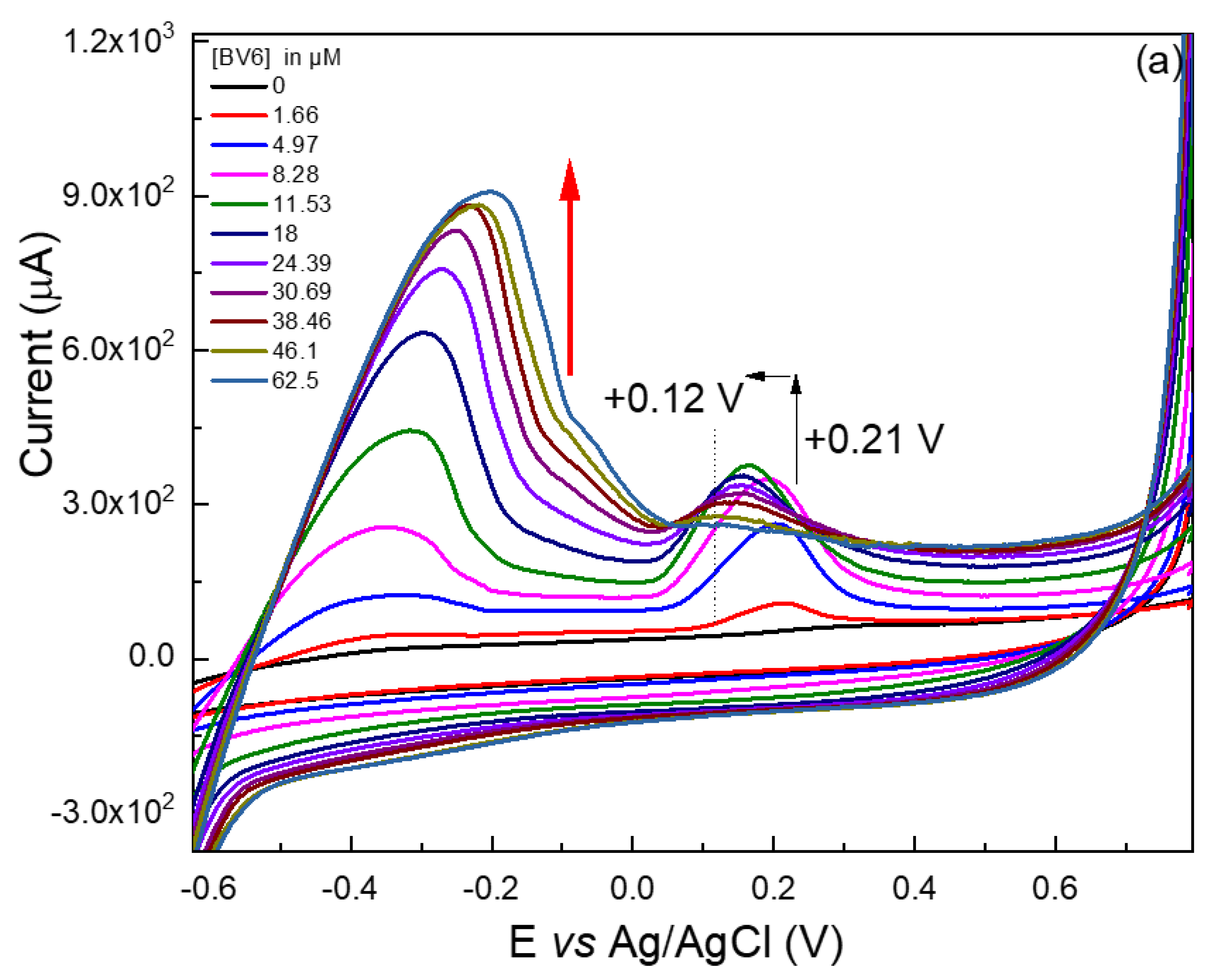
Figure 9a, this peak disappeared once BV6 was added. However, a similar peak appeared at +0.21V that could be related to the peak at +0.31 V. The shape and maximum value of this second peak will be affected by the progressive addition of BV6 to the electrolyte solution, allowing in this way the detection of BV6. Preliminarily, this suggests that the perovskite actively interferes with the BV6 towards its detection, or else this peak would have remained invariant to the added drug concentration.
A high perovskite loading was possible to attain on the surface of the G–SiO2/FTO film electrode due to the high surface area of the film electrode and the molecular size of the perovskite used in this study. Adsorption of 40 μL of the resultant perovskite solution onto the film’s surface caused its dark yellow-orange coloration, which suggests a high surface coverage. It is plausible that due to the organic–inorganic nature of the perovskite, its active materials could exhibit a similar immobilization behavior as is typically the case for proteins on the surface of the host G–SiO2/FTO film electrode.
In a comparable study [
2] wherein a different type of perovskite was adsorbed on the surface of the same film electrode material, it was observed that the shape of the CV of the composite film was different on the return scan in contrast to the one presented above. This is likely due to the different chemical composition of the adsorbed perovskite and the possible partial oxidation of the previously reported immobilized perovskite.
The absence of a diffusion-based reversible wave in both studies suggests that these particular 3D-like perovskites are incapable of shifting by diffusion through the G–SiO2/FTO film electrode structure, if perovskites are to undergo a redox reaction. This suggests that no electron hopping occurs among neighboring perovskite nanoparticles immobilized on the surface of the film electrode.
2.5. Voltammetric BV6 Sensor
The quantitative voltammetric detection of BV6 on the perovskite/G–SiO
2/FTO film electrode was conducted via CV and the results obtained are shown in
Figure 9a. Upon consecutive additions of increasing amounts of BV6, two large anodic peaks at −0.36 V and at +0.21 V can be observed. A peak at −0.36 V starts to appear and progressively increases and shifts to less negative biases, to −0.19 V. Similarly, the small anodic peak of the perovskite-modified film electrode at +0.21 V, see
Figure 8c, starts to increase as well and shifts to less positive biases, to +0.15 V. Both observations are due to the high specific area and increased conductivity of the film with the adsorbed perovskite.
The current response after each BV6 addition is relatively fast, reaching the steady-state value within a minute. Both anodic peaks are probably due to the oxidation of BV6 on the surface of the modified film electrode and are irreversible. It seems that these anodic peaks depend on the immobilized perovskite and the amount of BV6 added. It is also essential to note that during the CV measurements the perovskite remains fixed and stable on the surface of the film electrode that is immersed in the organic solvent. Perovskite desorption does not occur, as this would have been evident from the coloration of the electrolyte solution that does not take place.
Like in a recent study related to the oxidation of losartan [
2] on the surface of a perovskite/G–SiO
2/ITO film, it is suggested that also in this case the immobilized perovskite serves as an oxidation center for BV6. It is possible that this was facilitated by the transformation of the perovskite into another type from its pristine form. It is probable that BV6 redox reactions could be catalyzed by the perovskite itself. Also, supplementary experiments have been performed to elucidate possible electrochemical reaction steps, such as high-performance liquid chromatographic differentiation of the used solutions under acetonitrile/water, in order to detect substantial degradation species of BV6 or any other perovskite/BV6 species, which were not found. Furthermore, based on the facts that electrodes without perovskite did not show any BV6 detection, neither did perovskite-containing electrodes under blank solutions, it is therefore suggested that the BV6 was likely being detected through a more complex procedure in the organic solvent. As the negative electrode attracts BV6 molecules, containing Br counter ions, these are mixed with the perovskite’s bromine. The net result is that upon the voltage-forced oxidation, the complex BV6/perovskite species undergo a redox reaction, providing the detected peaks. The proposed catalytic function of BV6 is definitely related to the increase, as well as to the shift of both anodic peaks and particularly to the one at +0.21 V that shifts to +0.12 V upon the addition of increasing BV6 concentrations. Before the addition of BV6, the perovskite-modified G–SiO
2/FTO film electrode exhibits a small ill-defined anodic peak at +0.21 V for at least five consecutive CV scans, suggesting that maybe part of the perovskite is consumed or oxidized on the surface of the film electrode, as was discussed by us and others in the literature [
2,
27].
Figure 9b displays a background corrected peak current at −0.36 V versus the BV6 concentration plot, the gradual increase in the electrocatalytic anodic current maximum of the first anodic peak at −0.36 V upon increasing additions of BV6 in the electrolyte DCM + TBAH in the range of 0–65 × 10
−6 M fitted the apparent linear with a computed correlation coefficient of 0.9767; the CV experimental linear range was set to be from 1 to 18 × 10
−6 M and is displayed clearly in
Figure 9b, after background current subtraction. The detection limit LOD was estimated as 3.5 × 10
−6 M. Using the respective areas under the curves from −0.52 V up to 0.04 V, instead of the peak values, provides a respective LOD of 1.5 × 10
−6 M, where the endpoint of each curve has been subtracted as baseline.
Figure 10 shows the CVs of a bare G–SiO
2/FTO film electrode before and after the progressive addition of increasing concentrations of BV6. A slight progressive increase in the anodic current occurs at +0.3 V due to the addition of 25–75 × 10
−6 M (there is no increase for lower concentrations) of BV6 in DCM + TBAH electrolyte solution. The quite weak anodic peak is probably also due to the oxidation of BV6 on the surface of the bare film electrode which could also slightly contribute to this. This suggests that the supporting material (the conducting glass and the film of graphite paste and SiO
2) is also slightly catalytic toward the oxidation of BV6. This is quite advantageous as there is a synergy between the bare film electrode and the specificity of the perovskite catalyst, producing a hybrid catalyst which is more active than the individual materials.
The reproducibility of the perovskite-modified film electrodes was also tested. Five separate films were prepared under the same conditions and were tested for the voltammetric determination of BV6 and gave very similar results with a relative standard deviation of 4%.
Finally, the stability of the perovskite-modified film electrodes was tested. After their use as a sensor for the detection of BV6, they were stored at room temperature for up to four months without losing their voltammetric response towards BV6 detection. They maintained their OA absorption spectra, while the PL showed some defect states, which were reverted after a long storage period. In
Figure S1, the CVs of a four-month-old perovskite-modified film electrode after the addition of increasing BV6 concentrations are exhibited. Both anodic peaks due to the addition of BV6 could be observed. However, it is not recommended to reuse these composite films as their prolonged use could trigger issues like desorption of the perovskite from the surface of the film, due to its Pb content. Also, there is the possibility that there are minute traces of BV6 adsorbed at the composite electrode, rendering it less sensitive after multiple usage. Through observations, the active perovskite compound allows BV6 electrochemical measurements even after a period of four months, as evidenced by the OA and PL patterns, while even the four-month-old perovskite can still perform BV6 detection measurements as evidenced in the
Supplementary Information Figure S1. This is the first study of the use of a modified electrode for the electrochemical determination of BV6.
3. Materials and Methods
3.1. Chemicals
Lead bromide (PbBr2, 99.999% trace metals basis), methyl amine (CH3NH2 abbr. MA, 40% solution in water), Ν,Ν’-dimethylformamide (DMF, 99.8%), dimethyl sulfoxide (abbr. DMSO, anhydrous, >99.9%), hydrobromic acid (HBr, ACS reagent, 48%), and tetra-n-butylammonium hexafluorophosphate (TBAH, 98%) were purchased from Acros Organics (Geel, Belgium); dichloromethane (DCM), and sodium silicate (Na2SiO3) were supplied by Fisher Chemicals (Hampton, NH, USA); FTO TEC15 glass slides (2.2 mm thick and 15 Ohm/sqr sheet resistance) were purchased from XOP Glass, Castellón, Spain. Graphite powder (synthetic, APS 7–11 micron, 99%) was obtained from Alfa Aesar (Kandel, Germany). BV6 (4-butyl-Ν,Ν -bis{[2-(2H-tetrazol-5-yl)biphenyl-4-yl]methyl}imidazolium bromide) was supplied by NewDrug P.C., Patras Science Park (Patras, Greece), which also provided any needed nuclear magnetic resonance data or high-performance liquid chromatographic results.
3.2. Preparation of Graphite/SiO2 Film Electrodes
The G–SiO
2 film electrodes were prepared as reported previously [
2]. In brief, 300 mg of silicate liquid polymer (50% Na
2SiO
3, pH 12–13) was mixed with 20% of its weight in graphite powder and placed under stirring for homogenization at 40 °C, acquiring a paste-like texture. The paste was then sonicated for 2 min. After that, 100 μL of the silicate/graphite paste was applied on the surface of a clean conducting FTO glass slide by the “doctor blade” technique (coating process). Before the application of the paste, the FTO glass slide was masked with 3M Magic Scotch tape (type 810, thickness 62.5 μm) for the control of the thickness and width of the area spread. The resulting G–SiO
2 films were then allowed to dry at room temperature before being heated at 330 °C for 100 min. The final G–SiO
2/FTO films were divided in 2.5 × 1 cm
2 samples.
3.3. Perovskite Synthesis and Its Immobilization on the G–SiO2/FTO Electrode
Synthesis of the 3D CH3NH3PbBr3 was conducted by dissolving 367 mg of PbBr2 in 3 mL DMF with the continuous addition of 0.5 mL HBr, while stirring at 80 °C until an optically clear solution was obtained. In a different vial, 31 mg of methylamine was mixed in a solution containing 1 mL HBr and 2 mL DMF and left under stirring, without heating, for 1 min. The two solutions were then mixed, yielding a bright orange precipitate. Afterwards, the mixture was filtered to obtain the orange crystals. The rest of the solution was placed in a Petri dish at 80 °C until more crystals were formed and the solvents were fully evaporated. For the preparation of the film, 60 mg of 3D Br perovskite was dissolved in 200 μL DMF, yielding a transparent solution. Afterwards, 40 μL of the perovskite dissolved solution was drop-casted on the surface of the G–SiO2/FTO electrode (size: 2.5 × 1 cm2). Finally, these film electrodes were left to dry at 60 °C for 24 h.
3.4. Preparation of the BV6 Solution
BV6 (4-butyl-Ν,Ν-bis{[2-(2H-tetrazol-5-yl)biphenyl-4-yl]methyl}imidazolium bromide) is a synthetic designed molecule synthesized by NewDrug P.C. [
28].
3.5. Characterization of Perovskite/G–SiO2/FTO Hybrid Electrode Films
The G–SiO2 films on FTO glass substrates, with or without perovskite attached on their surface, were characterized by power X-ray diffraction (XRD), within the 2θ value range of 2–80°, using a Bruker D8 Advanced X-ray diffractometer (Bruker AXS GmbH, Karlsruhe, Germany) equipped with a Lynx Eye detector and Ni filtered Cu Ka radiation. The surface morphology and thickness of the perovskite/G–SiO2 films on FTO glass, as well as their chemical composition, were analyzed by a ZEISS EVO MA 10 scanning electron microscope equipped with an energy dispersive spectroscopy (EDS) analyzer (Oxford Instrument, Abingdon, UK) with 127 eV resolution.
3.6. Optical Measurements
All measurements were performed under air at room temperature. Specifically, the UV–Vis optical absorption spectra were recorded on a UV-1800 Shimadzu spectrophotometer (Shimadzu Europa, Duisburg, Germany) in the range of 200–800 nm, at a sampling step of 0.5 nm, using 1.5 nm slits. As a light source, a combination of halogen and deuterium (D2) lamps were used. The samples were measured as thin or thick spin-coated films on quartz substrates. The same samples were mounted in a Hitachi F-2500 fluorescence spectrophotometer (Hitachi Ltd., Tokyo, Japan) employing a xenon 150 W lamp and an R928 photomultiplier, and their photoluminescence spectra were recorded.
3.7. Electrochemical Measurements
The electrochemical behavior of the film electrodes was investigated by cyclic voltammetry using an Autolab PGSTAT101 potentiostat (Metrohm Autolab, Utrecht, The Netherlands) and a 5 mL conventional three-electrode electrochemical cell, with a platinum wire counter electrode, a Ag/AgCl/KClsat reference electrode, and a perovskite/G–SiO2 film on FTO glass as the working electrode. The electrolyte solution used was 5 mL DCM with 0.1 M of TBAH. The same experimental setup and conditions were used in the determination of BV6 in a solution. An aqueous BV6 stock solution (dissolving 15 mg of BV6 in 1 mL distilled water) was spiked into the cell using a micro-syringe. Cyclic voltammograms (CVs) were recorded 1 min after each BV6 addition. All electrochemical measurements were carried out at room temperature.


 ,
, 


