Communication

CGA-VLP: High Accuracy Visible Light Positioning Algorithm Using Single Square LED with Geomagnetic Angle Correction

1
School of Automation Science and Engineering, South China University of Technology, Guangzhou 510641, China
2
School of Materials Science and Engineering, South China University of Technology, Guangzhou 510641, China
3
School of Information Engineering, South China University of Technology, Guangzhou 510641, China
4
School of Mathematics, South China University of Technology, Guangzhou 510641, China
*
Author to whom correspondence should be addressed.
Photonics 2022, 9(9), 653; https://doi.org/10.3390/photonics9090653
Submission received: 15 August 2022 / Revised: 9 September 2022 / Accepted: 12 September 2022 / Published: 14 September 2022
(This article belongs to the Special Issue Advances in Visible Light Communication)

Abstract

:
Visible light positioning (VLP), benefiting from its high accuracy and low cost, is a promising technology for indoor location-based services. In this article, the theoretical limits and error sources of traditional camera-based VLP systems are analyzed. To solve the problem that multiple LEDs are required and auxiliary sensors are imperfect, a VLP system with a single square LED which can correct the geomagnetic angle obtained from a geomagnetic sensor is proposed. In addition, we conducted a static positioning experiment and a dynamic positioning experiment integrated with pedestrian dead reckoning on an Android platform to evaluate the effectiveness of the proposed method. According to the experimental results, when the horizontal distance between the camera and the center of the LED is less than 120 cm, the average positioning error can be retained within 10 cm and the average positioning time on the mobile phone is 39.64 ms.

1. Introduction

In recent years, indoor location-based services and applications, including personal localization and navigation, object searching, and robotics, have grown rapidly [1]. Moreover, indoor positioning is still a challenging problem since the performance of a Global Positioning System (GPS) decreases remarkably in an indoor environment due to the obstruction of the walls during signal transmission. A few techniques and devices have been proposed for indoor positioning systems (IPS) to improve the performance of indoor positioning. Firstly, wireless signals (such as Wi-Fi, Bluetooth, radio frequency identification, and ZigBee) are focused on and researched extensively, then the potential of light emitting diodes (LEDs) in indoor positioning is explored. In the past few years, many algorithms for LED-based positioning have been proposed and verified by experiments, presenting better positioning results or lower costs compared to those based on wireless signals [2].
Unlike traditional radio-based technology, visible light positioning (VLP) is a type of indoor positioning technology based on visible light communication (VLC) [3,4,5]. LEDs can transmit data over the air by modulating at a high frequency that is invisible to the human eye but perceivable by an image sensor (IS) or photodiode (PD). Using PD, or photo detector, which provides a converted current from the illumination, methodologies can be classified according to their received optical signals, namely, received signal strength (RSS) [6,7], time of arrival (TOA) [8]/time difference of arrival (TDOA) [9], angle of arrival (AOA), and fingerprinting [10]. Although PD is a common receiver of optical signals, it is not an ideal VLP device. Firstly, it is sensitive to the light intensity and diffuse reflection of the light signal, which is detrimental to high accuracy localization [11] (p. 1). Secondly, its detection area is too small [12] (p. 1) and will thus increase the LEDs needed. By contrast, camera-based VLP is favored by both industry and commerce due to its high positioning accuracy and good compatibility with user devices such as mobile robots and smartphones. Some state-of-the-art (SOTA), camera-based VLP systems have achieved centimeter-level accuracy on commodity smartphones [13] or mobile robots [14].
However, there are still some practical limitations. One of the most urgent issues is that VLP normally requires multiple LEDs in the camera’s field of view (FOV) [15,16,17], which means that lamps need to be densely distributed, and the effective positioning area becomes small. In order to reduce the number of LEDs required in the process, additional Micro-Electro-Mechanical System (MEMS) sensors are generally chosen to provide orientation information. However, as shown in previous research [18,19], another positioning error source owing to the inaccurate azimuth angle is introduced. In [11], with the employment of the inertial measurement unit (IMU) as the variable, a pair of comparative experiments was conducted. The error tripled when using the IMU due to the algorithm compensation and measurement error.
In this article, we put forward a single-LED localization system based on IS and geomagnetic sensor (GS). The LED used in this system is square in shape, which is common in daily life. Unlike the circular LEDs widely used before in VLP, which have numerous symmetry axes and offer less usable point features, being one feature of a circular LED [20], the square LED can provide not only displacement information but also rotation information which can effectively correct the geomagnetic angle obtained from the GS. In [21] (p. 12), the experiment illustrated that raw measurement of the heading can vastly deviate from the true value, with angle errors up to 60 degrees, which shows that the correction is not redundant. The innovative contributions are highlighted as follows:
  • We propose a VLP scheme based on the corrected geomagnetic angle (CGA-VLP) in which we relax the assumption on the minimum number of observable LEDs efficiently to one and improve the robustness in the harsh environment.
  • The proposed methodology can correct the geomagnetic angles obtained from GS, which could be further applied to other algorithms.
  • The scheme is evaluated in static and real-time environments through a tailor-made Android application and modulation drive, with pedestrian dead reckoning (PDR) functioning when LED is out of the camera’s FOV. The accuracy and real-time performance are both excellent for real applications.
The rest of this article is organized as follows: the second section illustrates the proposed CGA-VLP system. The verification results are then presented in the third section. Finally, we render our conclusions.

2. Methodology

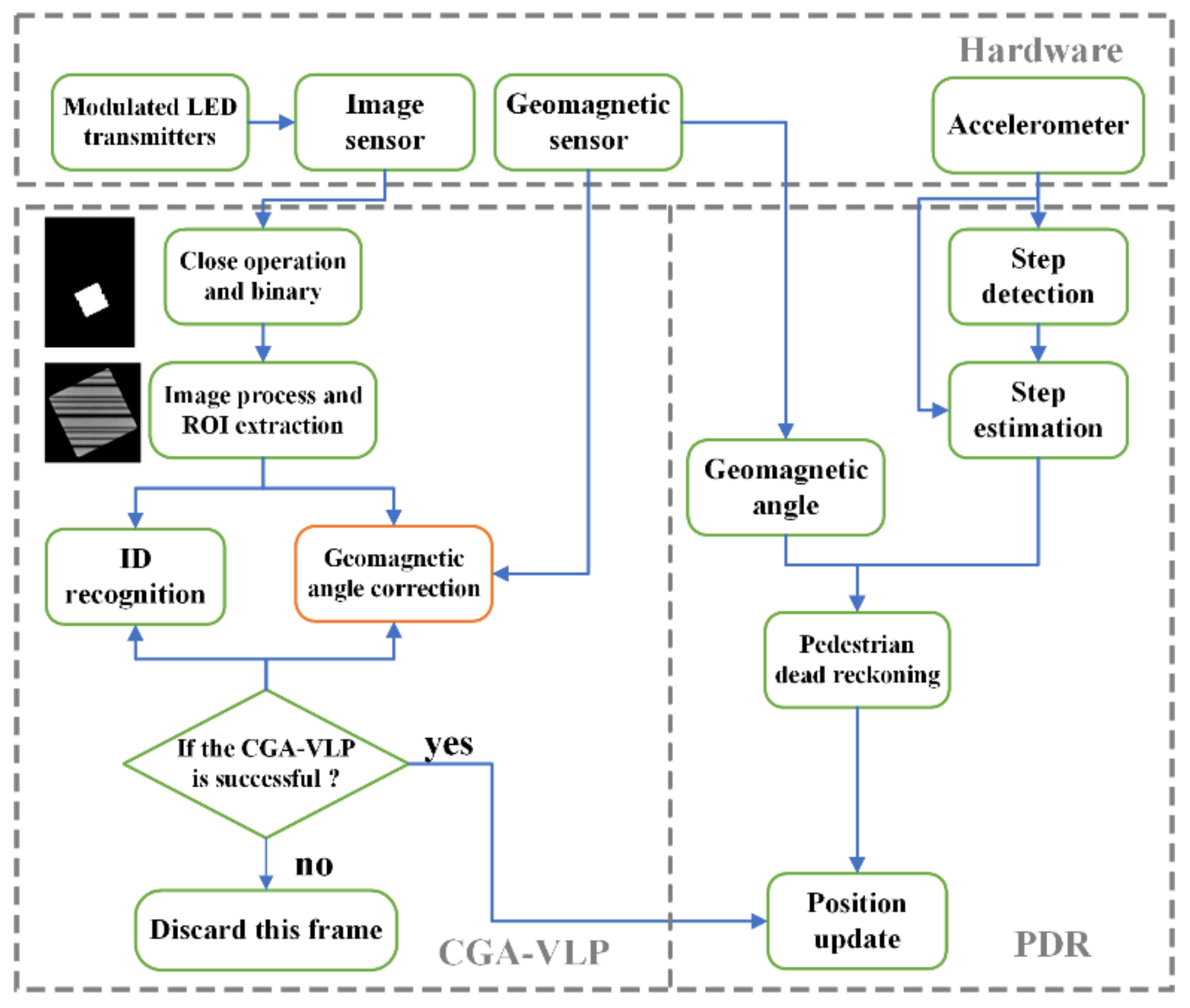
2.1. Overall Structure

The architecture of the proposed CGA-VLP system is shown in Figure 1. The modulated LED lamps with VLC functions are used as transmitters. The images are caught by Complementary Metal-Oxide-Semiconductor (CMOS) IS vertically and decoded to obtain their unique identities which are related to their global coordinates. The geomagnetic angle can be obtained from the GS, then corrected by using the geometric relation of the square LED in the images, which will be illustrated in detail in the next subsection. For a comprehensive understanding of VLC, we refer readers to our previous work [3]. PDR is another solution for IPS, which will be explained and fused with CGA-VLP in the experiment section.

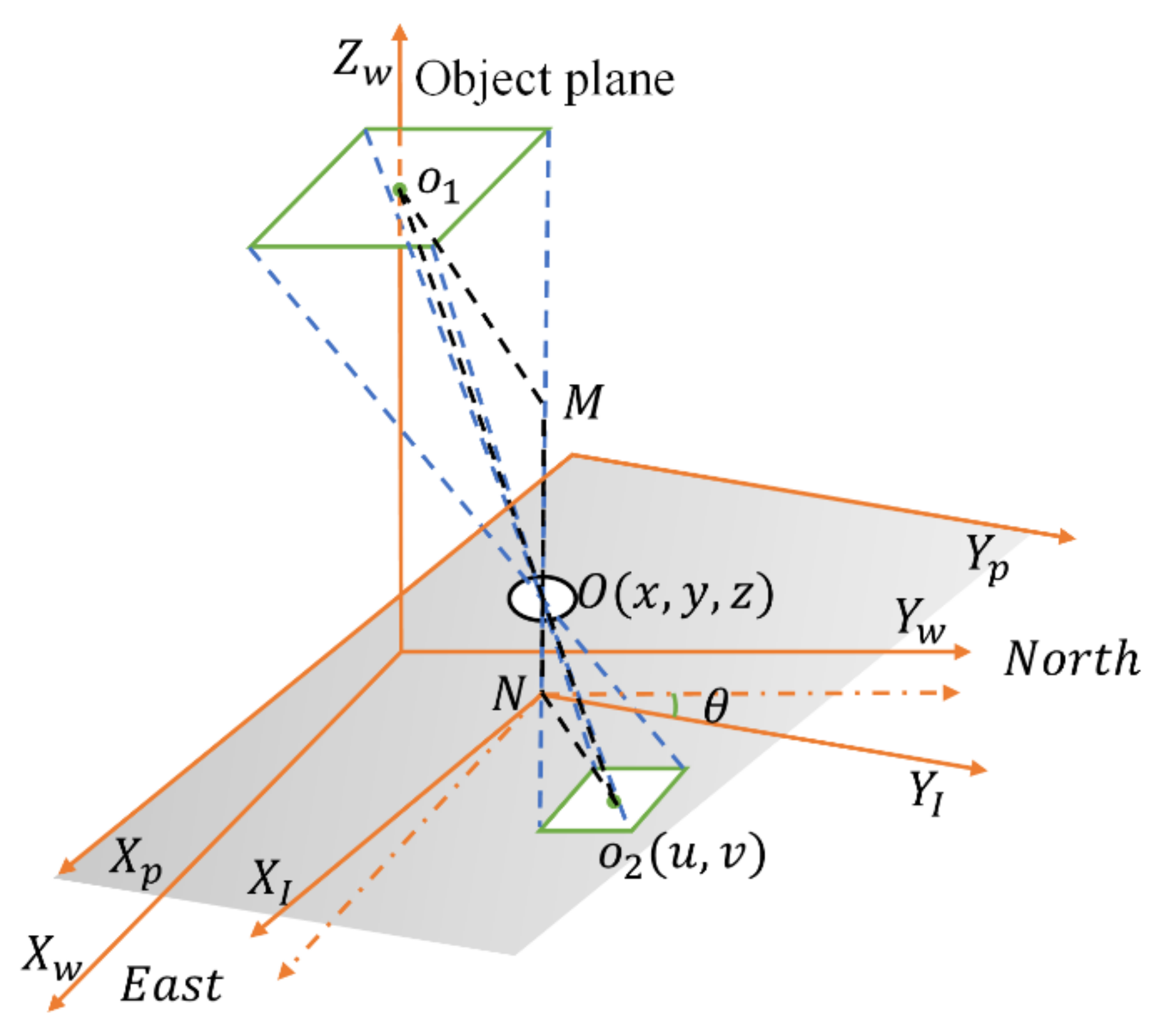
2.2. The Principle of Imaging Positioning

The model of the proposed VLP system is shown in Figure 2. The world coordinate (denoted as {W}), image coordinate (denoted as {I}), and pixel coordinate (denoted as {P}) are defined as follows, respectively. The origin point of the image coordinate system is the intersection point between the optical axis of the camera and the imaging plane of the image sensor. The relationship between the pixel coordinate and the image coordinate system can be denoted by the following formula:
m = i i 0 d m n = j j 0 d n ,
where i 0 ,   j 0 are the coordinates of the image sensor in the pixel coordinate system, located in the center of the image. The unit transformation of two coordinate systems is 1 pixel = d m   m m and 1 pixel = d n   m m .
The original point of the world coordinate system is the vertical projection of the lamp center to the ground, and X w , Y w are on the plane of the ground. The direction of the Y w axis can be arbitrary. For the sake of simplicity, it is set parallel with the direction of north in our scenario. The dashed coordinate system is to assist explanation and has no physical meaning. It shares the same origin point with the image coordinate system and is parallel with the world coordinate. The unit is pixel.
u v = cos θ sin θ sin θ cos θ u v .
Through digital image processing, the centroid coordinates u , v of LED are easy to obtain, which can then be transferred to the coordinates u , v in the virtual coordinate system through Equation (2). In addition, θ denotes the included angle of the two coordinate systems. Ignoring the tiny deviation of the x and y axes of the photosensitive device, d m and d n are approximately equal to   k . According to triangular similarity, the following equations can be obtained:
N O 2 M O 1 = N O M O =   k · u x =   k · v y ,
μ = u   x =   v y ,
where x , y , z are the coordinates of the camera lens in the world coordinate system, while μ is the conversion ratio of the pixel coordinate system and world coordinate system which can be calculated by employing the actual size and the image size of the LED. Through the above process, the 2D position of the mobile phone can be determined.
According to the imaging principle:
1 f = 1 M O + 1 N O ,
where f is the focal length.   z is accessible if the focal length is known. However, the camera of a smartphone usually has the function of automatically adjusting the focal length in order to obtain clearer images, thus making it only valid at one time. Therefore, in this article, we do not measure the focal length and the height of the camera is not considered.

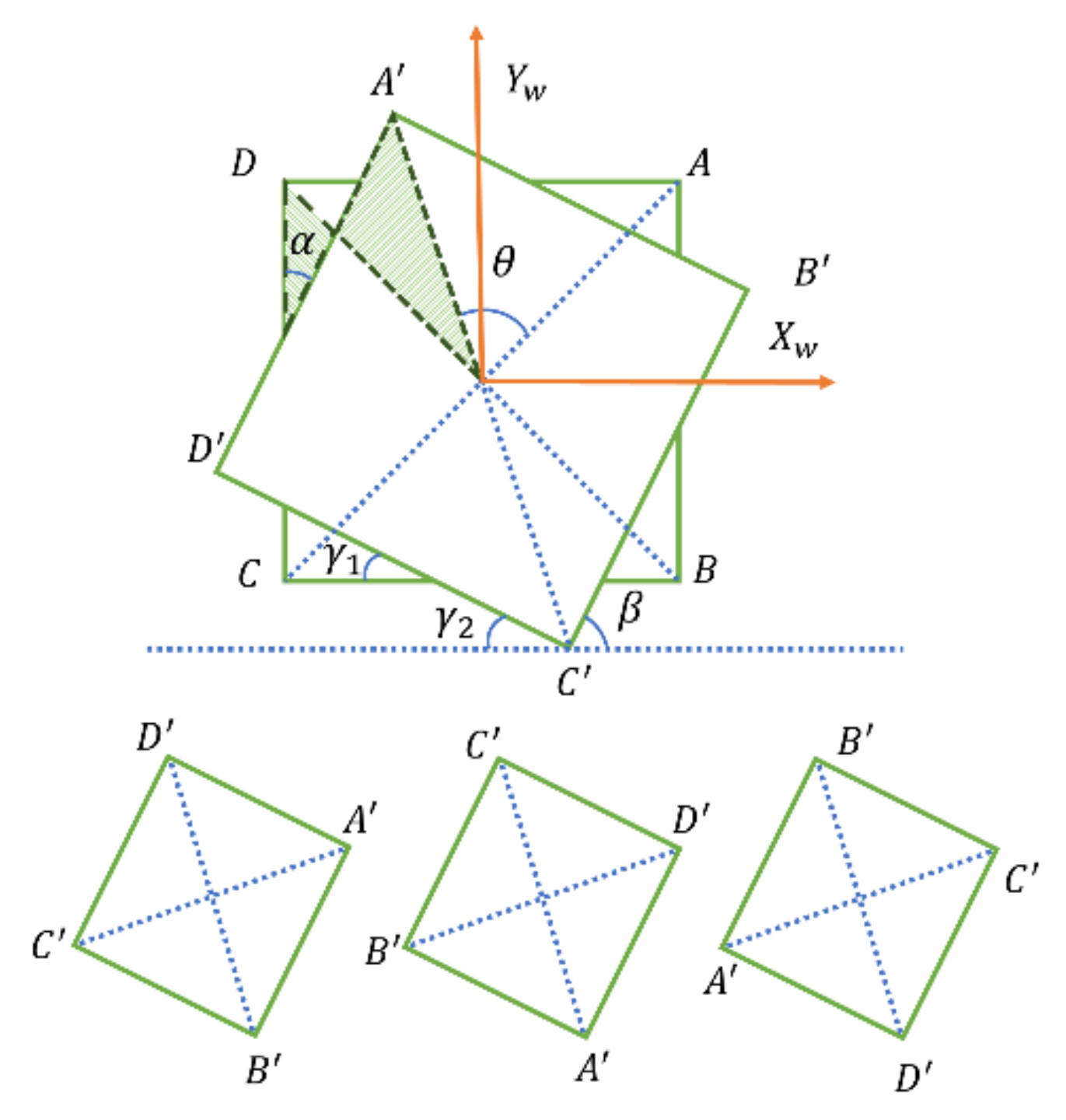
2.3. Geomagnetic Angle Correction

To obtain the rotation angle about the z axis in single-LED-based VLP algorithms, several methods can be used, such as utilizing a mark [22,23], or adopting sensors as assistance [24]. However, marks on the lamp will affect the illumination as well as the aesthetics. Currently, mobile phones always embed GS, which means that no additional equipment is needed if the geomagnetic angle is used. However, the indoor magnetic field is the superposition of the geomagnetic field and the interference field caused by the steel structure, elevators, cables, doors, and windows, so the geomagnetic angle detected indoors is always inaccurate [25] (p. 2). To correct the geomagnetic angle, the angle information of the square lamp is utilized. For the sake of simplicity, the LED is placed in a specific posture with one side of the square parallel to the direction pointing north. The initial posture of the phone is set with the geomagnetic angle equating to zero, where the photo of the LED captured vertically by the camera will resemble the square denoted as ABCD in Figure 3. When the phone spins, the LED revolves in the opposite direction on the picture. In this way, the clockwise rotation angle of the phone is exactly the geomagnetic angle; represented in the image is the rotation angle of the square denoted as θ in Figure 3. According to the similar triangle principle, it is easy to compute:
γ 1 = α = 90 ° θ .
Since γ 1 and γ 2 are corresponding angles, they are certainly equal in value and γ 2 is a reliable angle that we can measure from the image.
Corresponding to the four cases shown in Figure 3, there are four possible situations and the real projection cannot be distinguished from the image. The four possible values for real rotation angle γ are illustrated in Equation (7):
γ = γ 2 , γ = γ 2 + 90 ° , γ = γ 2 + 180 ° , γ = γ 2 + 270 ° ,
which will be compared to the value obtained from the geomagnetic sensor, then the angle with the smallest difference will be selected as the corrected geomagnetic angle. In the practical application, there may be difficulty in the installation of lamps according to the above settings. However, it does not matter as long as the γ 0 , which indicates the included angle between one side of the lamp and due north, is noted. It can be calculated through the shot taken when the phone is in the initial posture, namely, β shown in Figure 3. In addition, γ 2 should subtract γ 0 before being used in Equation (7). After that, the algorithm is the same.

3. Experiments and Analysis
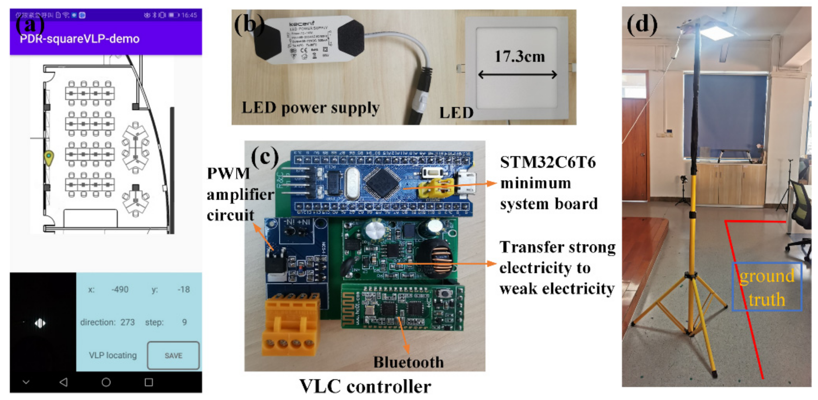
3.1. Receiver

The system is made up of a receiver and transmitters. The receiver is a mobile device, namely, Huawei P10. The IS used in this experiment is the embedded front camera. The exposure time of the camera was set as 0.05 ms to ensure the stripes and the edges of the LED are clear. This parameter may vary depending on the aperture size of different cameras. The resolution is optional but was selected as 1920 × 1080 in our experiment, which is what we recommend so that the picture of this resolution can meet the requirements of clarity while not being too large. With the rolling shutter effect, the exposure of the camera is conducted in a row-by-row manner instead of exposing the whole image at a single moment, so the flash of the LED will form stripes in the image. The image is processed successively by close operation, gray processing, binarization, and region of interest (ROI) extraction. To eliminate the interference of other lamps, the ROI with a shape close to a square and a size within a certain range is selected and decoded. In addition, the contours in the ROI will be detected using Canny operators, then the Hough transformation is employed to extract the lines, with which the geomagnetic angle will be corrected, as shown in Figure 3. Thus, the precise position of the camera can be obtained. Due to the stripes, there will be many horizontal lines, so the angle close to zero calculated from the picture needs to be discarded. If the sides of the square are also parallel with the sides of the picture, the contour cannot be distinguished from the stripes. Therefore, under that circumstance, the correction will be abolished and the raw geomagnetic angle will be used.
In our experiments, all data capturing and processing are performed on the mobile device, through a tailor-made application, as shown in Figure 4a. The application can display direction, positioning results, and positioning mode in real time. In addition, the data can be exported in a table for further analysis. When there is no LED in the camera’s FOV, the application will execute PDR which will be introduced in a later section.

3.2. Transmitters

The transmitters are modulated LEDs mounted to the light pole, as shown in Figure 4d. To modulate LED more conveniently, a tailor-made VLC controller module that integrates the Bluetooth modulation function was designed.
The principle of the VLC controller is revealed in Figure 5. The alternating current is converted to direct current by the LED power supply, as shown in Figure 4b. The buck module is responsible for the power supply of the Bluetooth and the MCU, namely, STM32C6T6. In addition, the Pulse Width Modulation (PWM) amplifier circuit amplifies the PWM signal outputted by the MCU to the rated voltage of the LED. The current is then modulated by the VLC controller to illume the LED and transmit the signal simultaneously. The Bluetooth can communicate with mobile phones and then transfer the instructions to the MCU which controls the on–off state of the LED. For convenience, the off-the-shelf modules are organized on a printed circuit board (PCB), at the corner of which the power interface and the interface for LED are gathered, as shown in Figure 4c.
The time-varying switch state of the lamp represents binary data sequences which consist of the header and unique identification (ID). After modulation, the LED will send the specified data circularly at the same time of illumination.

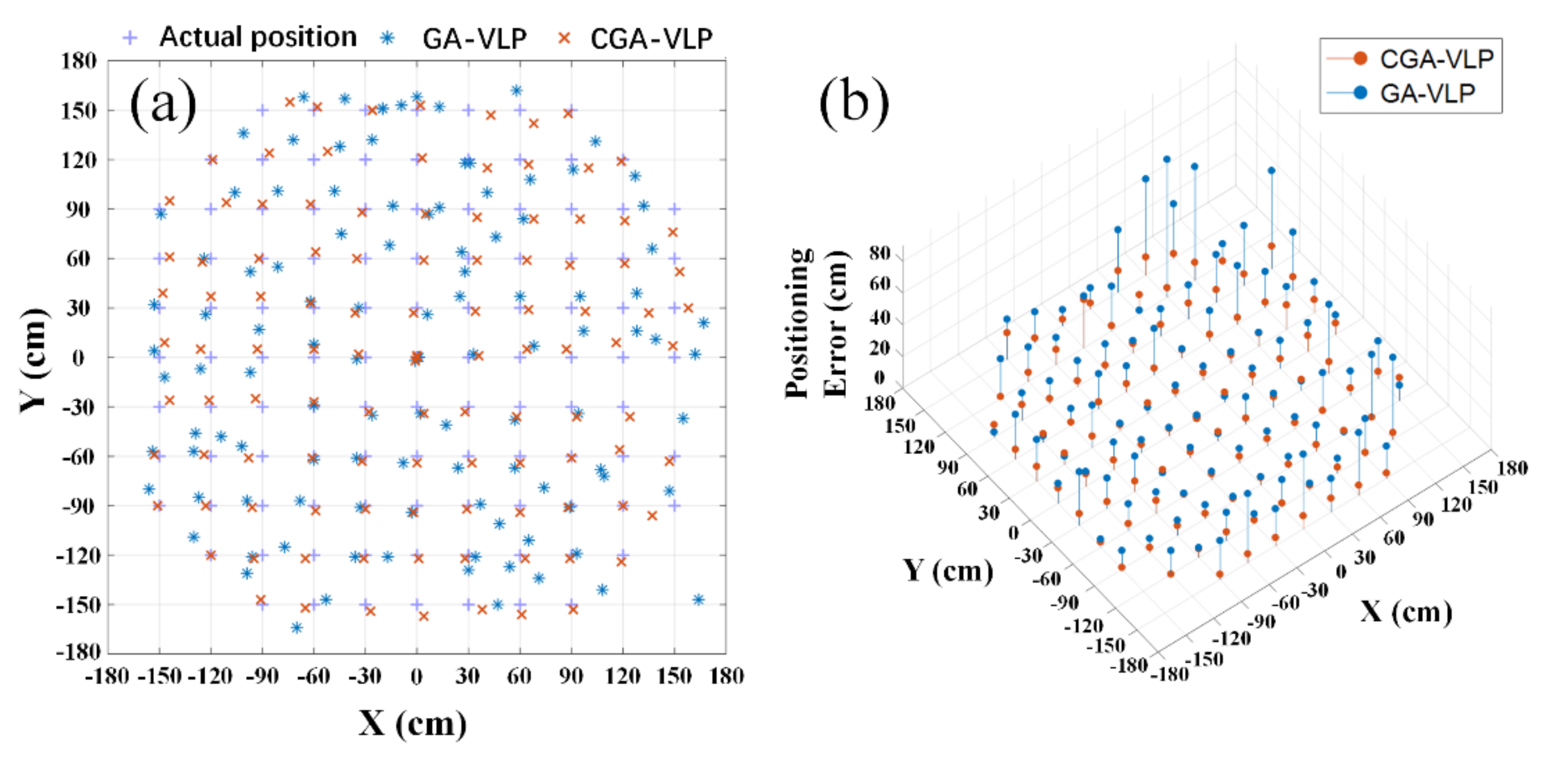
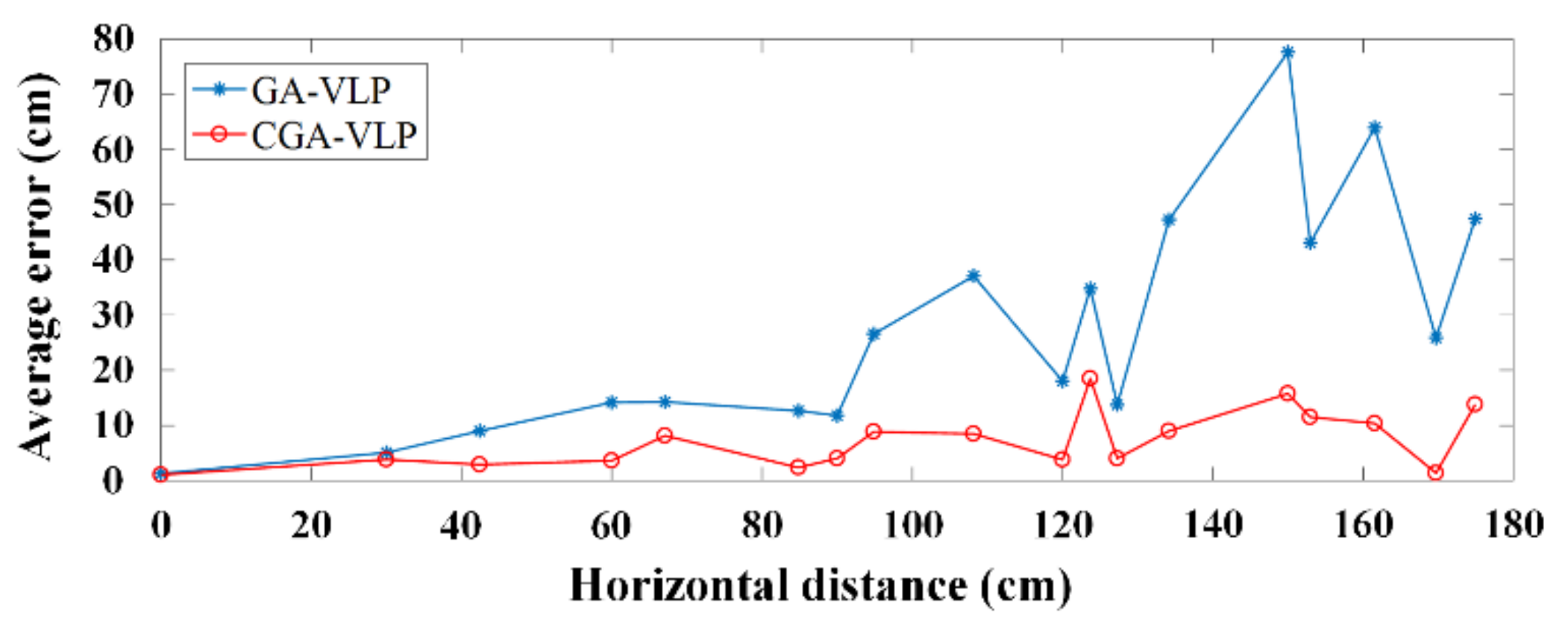
3.3. CGA-VLP System Positioning Accuracy

To evaluate the position accuracy of the proposed positioning system, two series of experiments were performed. The first series was to test the stationary positioning performance of CGA-VLP. The square lamp was installed horizontally 260 cm above the ground, with the mobile phone placed flat on the ground.
We chose 108 evenly spaced points around the LED center and calculated the positioning results employing CGA-VLP and GA-VLP, respectively. The limited horizontal range of positioning was 150 cm from the center of the LED.
Figure 6 shows the positioning results and the corresponding errors. The results of CGA-VLP are displayed in red. CGA-VLP’s positioning effect is significantly better than GA-VLP’s, namely, the blue ones, especially when the mobile phone is farther away from the center of the lamp.
We calculated the average error of the positioning results under the same horizontal distance, as shown in Figure 7. When the horizontal distance is under 120 cm, the maximum average positioning error of CGA-VLP is 8.5 cm. Even if the horizontal distance reaches 175 cm, the average positioning errors of CGA-VLP can still be maintained below 20 cm. In addition to the error of installing lamps, the experimental error comes from the combined action of the error of the ROI position and the error of the rotation angle. When the mobile phone is farther away from the center of the positioning area, the error of the ROI position increases. After multiplying by the rotation angle with error, the positioning error will sharply increase. By contrast, with the corrected geomagnetic angle, the positioning error will not increase as much.

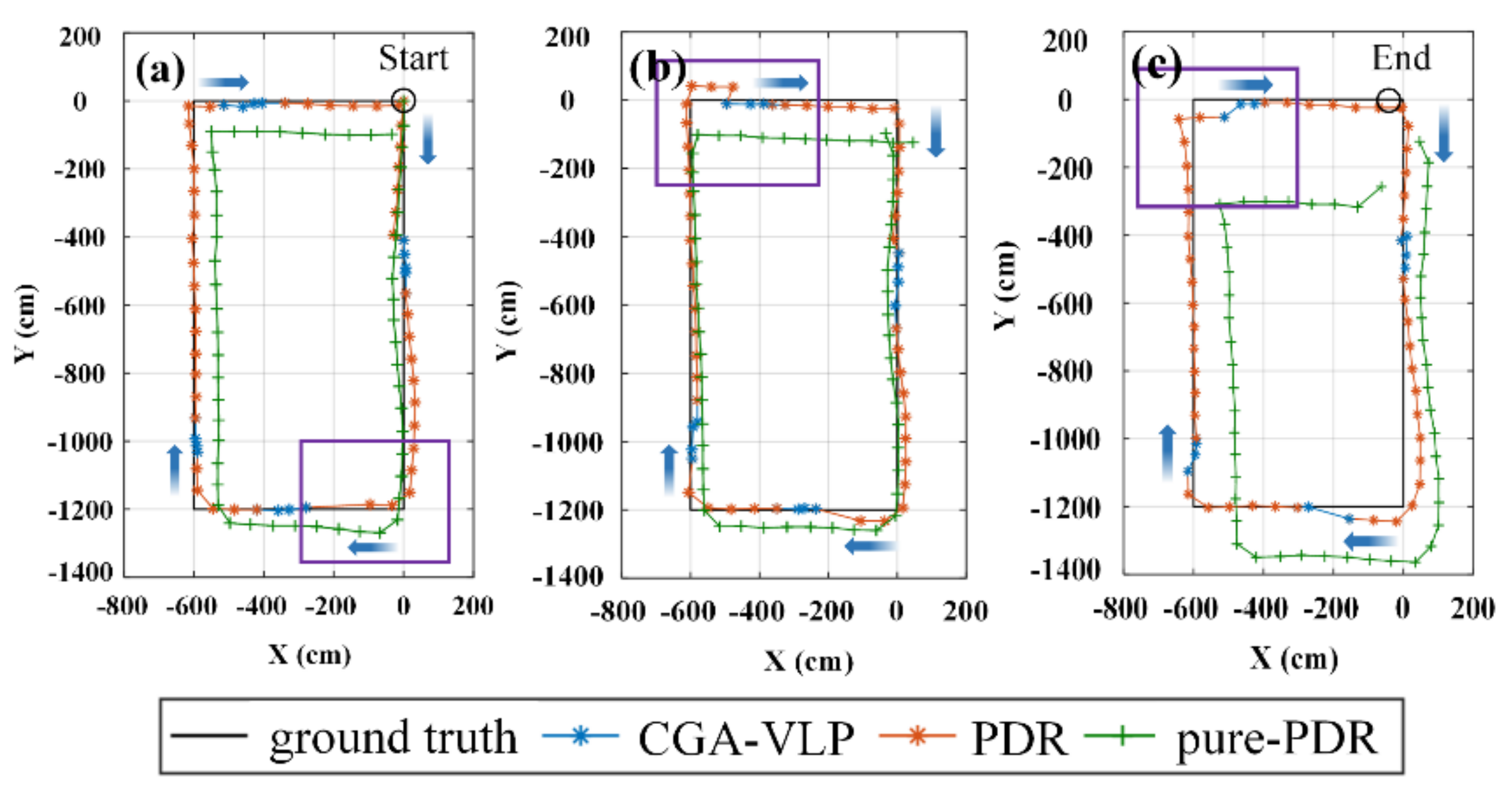
3.4. Dynamic Positioning

As mentioned above, the effective positioning area of VLP is confined by the camera’s FOV. Once the LED cannot be captured, the positioning cannot be executed. The demand for density of LEDs deems that VLP is not suitable for realistic application independently. Luckily, PDR is another solution for IPS. Generally, a PDR algorithm consists of three phases: step detection (SD), step length estimation (SLE), and position–solution update (PSU). Benefiting from the popularity of smartphones, the methodology is adored due to its simplicity and low cost [26]. Equation (8) illustrates the mechanism of PDR:
x n = x n 1 + l · c o s γ y n = y n 1 + l · s i n γ ,
where x n , y n is the current position coordinates, x n 1 , y n 1 is the position coordinates of the previous moment, and l is the size of each step. Unlike the schemes requiring signal generators installed in the environment before experiments, PDR uses sensors attached to the users to estimate relative positions to previous or known position, so it is more susceptible to cumulative error.
In this section, we fused VLP and PDR to adapt to real application scenarios. PDR was employed when VLP could not work, and VLP can correct the cumulative error of PDR. The flow chart of the scheme is shown in Figure 1. Peak detection [27] was adopted for SD, while the Weinberg model [28] was adopted for SLE. The heading angle obtained through the GS and the estimated stride length were then combined for PSU.
During the test, the smartphone maintains a horizontal state, with the top of the smartphone pointing to the moving direction. Limited by the size of the experimental site, the route was set as a 12 × 6 m rectangle. Three rounds around the rectangular path were completed in each experiment, so the route would be 108 m in total. For test operations, we equipped our laboratory with four LEDs, with one on each side of the rectangle. One of them is shown in Figure 4d, with a corner of the ground truth marked using red lines. More detailed parameters can be found in Table 1. We performed our experiment with two positioning methods simultaneously with the only difference between the methods being whether CGA-VLP was used when the LED was in the camera’s FOV. In order to show our experiment device and scene more clearly, we also made a simple demonstration video (see Video S1).

3.4.1. Accuracy of the Dynamic Positioning

The positioning results of different methods are represented by different colors, with the points connected by straight lines to show the trajectories. To prevent overlap, the results of the three laps are plotted separately. The positioning track corrected by CGA-VLP is roughly close to the actual route, while the track for pure-PDR increasingly deviates from the ground truth as the route lengthens, with the final error reaching 3 m. Missing detection, false detection, and wrong step estimation will all affect the distance, and inaccurate direction will cause the trajectory to drift. It is clear that the two trajectories are the same where there is no LED, but in the fusion positioning, the trajectory was pulled back to the actual route by the VLP before the PDR error is further expanded. As shown in the purple box in Figure 8a, the error of drift is corrected by VLP in time. In the purple box of Figure 8b, the positioning distance exceeds the actual walking distance, which is corrected through VLP, thus preventing the accumulation of the error. In addition, in the similar position of Figure 8c, the positioning distance is shorter than the real distance, which is also corrected by VLP.

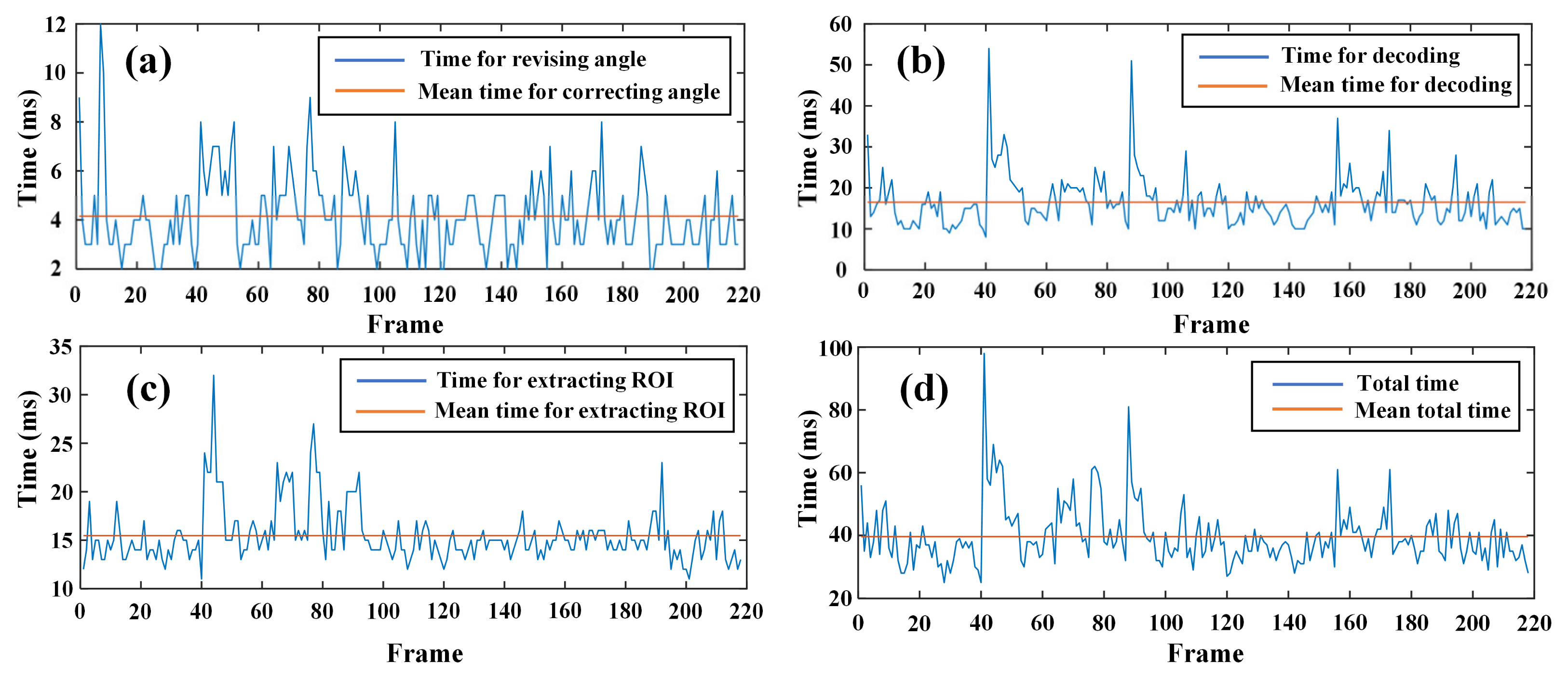
3.4.2. Real-Time Performance of the Dynamic Positioning

In this subsection, we focus on real-time performance. To reduce the burden of the phone, the frame rate was set as 5 fps, which was sufficient for calculating CGA-VLP several times when passing the lamp at normal speed. The data of seven experiments were recorded, of which 220 frames were with LED. The program execution time of the key steps of CGA-VLP was separately recorded and is shown in Figure 9. The mean time for correcting the rotation angle and decoding and extracting the ROI is 4.1415 ms, 16.5 ms, and 15.4679 ms, respectively. In addition, the total delay is 39.64 ms, on average, which also includes the time to create a new picture and convert it from bitmap format to RGB format, the time to make logical judgments in the main function, and the time to modify the UI. With variation due to the status of the phone and the quality of the photo, the calculation time fluctuated greatly on both sides of the average value. Despite this, the application of positioning when walking at a normal speed can be satisfied with the real-time performance of the algorithm. As shown in Figure 8, when people walk past the LED, the program can stably position through CGA-VLP several times, which precisely reflects the position of the pedestrian and correct errors.

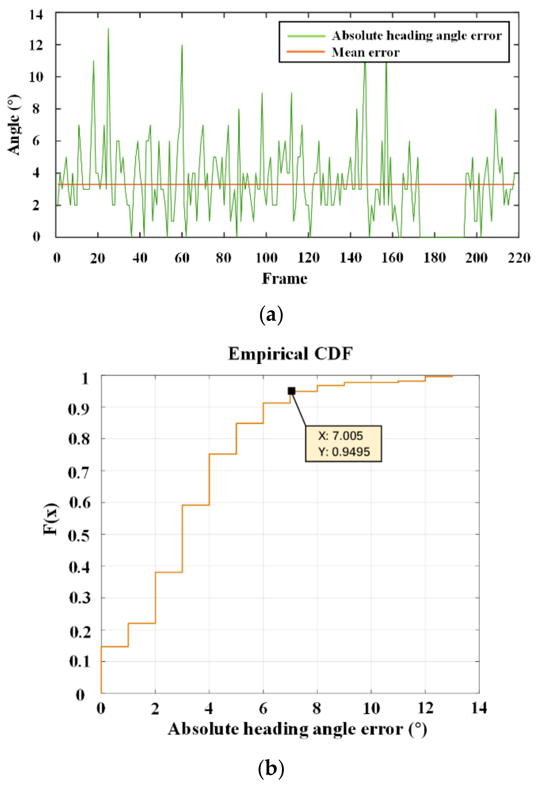
3.4.3. Accuracy of the CGA

In this subsection, the accuracy and error source of the proposed CGA are discussed. The errors of the corrected heading angle were calculated and presented in Figure 10, with the mean error 3.3°. The heading angle error shows randomness with several values over 10°, but according to the cumulative distribution function, more than 95% of errors are less than 8°. When the error of the geomagnetic sensor is within the range of 45° above and below the true value, the operation of correcting the geomagnetic angle is effective and does not contain systematic errors, to some extent ensuring the robustness of the algorithm. However, admittedly, there are still several limitations causing calculation error. Firstly, the proposed CGA-VLP requires the imaging plane and the square lamp to be parallel, which is almost impossible to achieve in the dynamic scenario, where the tester holds the phone while walking. Secondly, there may be errors in the process of extracting LED edges and calculating angles. Thirdly, the hand-held mobile phone will shake during walking. However, we think the practicality of the proposed method is acceptable since the blue lines shown in Figure 8 are close to the actual path.

3.5. Discussion

In this study, we propose a novel CGA-VLP algorithm which utilizes the GS to relax the number of observable LEDs required for positioning to one as well as correct the geomagnetic angle, thus ensuring accuracy. Consistent with previous research [25,29,30], the effect of correction of the geomagnetic angle when used for indoor positioning is remarkable. However, unlike these methods using filtering to correct the geomagnetic angle, the rotation information contained in the picture is utilized in our algorithm. In [25], after correction by the proposed 1D CNN-Kalman, 95% heading angle errors are less than 9°. The authors of [30] show that the mean error of the heading angle corrected by the Adaptive Cubature Kalman Filter is approximately 6°. By contrast, our CGA algorithm shows advantages both in terms of average error and cumulative error. In [23], the average positioning error is 2.3 cm, but the positioning area is 0.8 m × 0.8 m, with the calculation time 60 ms in a low-end embedded platform. In [11], the 2D error of 95% of points reaches 9 cm. In [31], the positioning error is up to 8.7 cm considering 90% of points. In general, the CGA-VLP has advantages in accuracy and delay. It is worth mentioning that if the CGA-VLP is used in a robot where the camera could be fixed and stable, the error caused by unstrict parallelism between LED and the imaging plane may be avoidable; we plan to further explore this in our future research. In addition, the correction is limited when the stripes caused by VLC are parallel with the side of the square, which is also an aspect we want to improve.

4. Conclusions

In this article, we proposed a VLP system with a single square LED which can correct the geomagnetic angle obtained from the GS. The static experiment showed that although the positioning error would increase as the phone moved farther away from the center of the LED, it could still be maintained reliably within 10 cm when the horizontal distance was less than 120 cm, while the positioning error for GA-VLP reached 40 cm. The algorithm was also tested and verified in a dynamic scenario fusing PDR. Positioning ability and real-time performance were both sufficiently excellent for live applications. The total delay was 39.64 ms, on average. In the future, we expect to explore the practical application of the proposed CGA-VLP in robots, improve its performance in terms of the effective positioning area and practicality, and implement tight fusion of PDR and VLP with the Kalman filter to improve its accuracy.

Supplementary Materials

The following supporting information can be downloaded at https://www.mdpi.com/article/10.3390/photonics9090653/s1, Video S1: Demo for the fusion of CGA-VLP and DPR.

Author Contributions

Methodology: C.Y. and W.G.; Experiment and Analysis, C.Y. and D.Y.; Writing, C.Y.; Visualization, J.H. and C.Y.; Hardware, C.Y.; Proofreading, W.G., J.C. and S.W; Funding, S.W. All authors have read and agreed to the published version of the manuscript.

Funding

This work was funded in part by the Guangdong Science and Technology Project under Grant 2017B010114001, in part by the National Undergraduate Innovative and Entrepreneurial Training Program under Grants 202010561158, 202010561155, 202110561162, 202110561165, and 202110561163, and in part by the Guangdong Provincial Training Program of Innovation and Entrepreneurship for Undergraduates under Grant S202010561272.

Institutional Review Board Statement

Not applicable.

Informed Consent Statement

Not applicable.

Data Availability Statement

Not applicable.

Conflicts of Interest

The authors declare no conflict of interest.

References

  1. Alletto, S.; Cucchiara, R.; Del Fiore, G.; Mainetti, L.; Mighali, V.; Patrono, L.; Serra, G. An indoor location-aware system for an IoT-based smart museum. IEEE Internet Things J. 2016, 3, 244–253. [Google Scholar] [CrossRef]
  2. Zhuang, Y.; Hua, L.C.; Qi, L.N.; Yang, J.; Cao, P.; Cao, Y.; Wu, Y.P.; Thompson, J.; Haas, H. A survey of positioning systems using visible LED lights. IEEE Commun. Surv. Tutor. 2018, 20, 1963–1988. [Google Scholar] [CrossRef]
  3. Song, H.Z.; Wen, S.S.; Yang, C.; Yuan, D.L.; Guan, W.P. Universal and effective decoding scheme for visible light positioning based on optical camera communication. Electronics 2021, 10, 1925. [Google Scholar] [CrossRef]
  4. Chow, C.W.; Chen, C.Y.; Chen, S.H. Enhancement of signal performance in LED visible light communications using mobile phone camera. IEEE Photonics J. 2015, 7, 7903607. [Google Scholar] [CrossRef]
  5. Chen, Y.; Ren, Z.M.; Han, Z.Z.; Liu, H.L.; Shen, Q.X.; Wu, Z.Q. LED based high accuracy indoor visible light positioning algorithm. Optik 2021, 243, 166853. [Google Scholar] [CrossRef]
  6. Sun, X.; Zhuang, Y.; Huai, J.; Hua, L.; Chen, D.; Li, Y.; Cao, Y.; Chen, R. RSS-based visible light positioning using non-linear optimization. IEEE Internet Things J. 2022, 9, 14134. [Google Scholar] [CrossRef]
  7. Chen, Y.; Zheng, H.; Liu, H.; Han, Z.Z.; Ren, Z.M. Indoor High Precision Three-Dimensional Positioning System Based on Visible Light Communication Using Improved Hybrid Bat Algorithm. IEEE Photonics J. 2020, 12, 6802513. [Google Scholar] [CrossRef]
  8. Wang, T.Q.; Sekercioglu, Y.A.; Neild, A.; Armstrong, J. Position accuracy of Time-of-Arrival based ranging using visible light with application in indoor localization systems. J. Lightwave Technol. 2013, 31, 3302–3308. [Google Scholar] [CrossRef]
  9. Jung, S.-Y.; Hann, S.; Park, C.-S. TDOA-based optical wireless indoor localization using LED ceiling lamps. IEEE Trans. Consum. Electron. 2011, 57, 1592–1597. [Google Scholar] [CrossRef]
  10. Shi, C.; Niu, X.; Li, T.; Li, S.; Huang, C.; Niu, Q. Exploring Fast Fingerprint Construction Algorithm for Unmodulated Visible Light Indoor Localization. Sensors 2020, 20, 7245. [Google Scholar] [CrossRef]
  11. Huang, H.Q.; Lin, B.; Feng, L.H.; Lv, H.C. Hybrid indoor localization scheme with image sensor-based visible light positioning and pedestrian dead reckoning. Appl. Opt. 2019, 58, 3214–3221. [Google Scholar] [CrossRef]
  12. Wang, Y.; Hussain, B.; Yue, C.P. Arbitrarily tilted receiver camera correction and partially blocked LED image compensation for indoor visible light positioning. IEEE Sens. J. 2022, 22, 4800–4807. [Google Scholar] [CrossRef]
  13. Fang, J.B.; Yang, Z.; Long, S.; Wu, Z.Q.; Zhao, X.M.; Liang, F.N.; Jiang, Z.L.; Chen, Z. High-speed indoor navigation system based on visible light and mobile phone. IEEE Photonics J. 2017, 9, 8200711. [Google Scholar] [CrossRef]
  14. Guan, W.; Huang, L.; Wen, S.; Yan, Z.; Liang, W.; Yang, C.; Liu, Z. Robot localization and navigation using visible light positioning and SLAM fusion. J. Lightwave Technol. 2021, 39, 7040–7051. [Google Scholar] [CrossRef]
  15. Xu, J.J.; Gong, C.; Xu, Z.Y. Experimental indoor visible light positioning systems with centimeter accuracy based on a Commercial smartphone camera. IEEE Photonics J. 2018, 10, 7908717. [Google Scholar] [CrossRef]
  16. Guan, W.; Zhang, X.; Wu, Y.; Xie, Z.; Li, J.; Zheng, J. High precision indoor visible light positioning algorithm based on double LEDs using CMOS image sensor. Applied Sciences. 2019, 9, 1238. [Google Scholar] [CrossRef]
  17. Liang, Q.; Lin, J.H.; Liu, M. Towards robust visible light positioning under LED shortage by visual-inertial fusion. In Proceedings of the 10th International Conference on Indoor Positioning and Indoor Navigation (IPIN), Pisa, Italy, 30 September–3 October 2019. [Google Scholar]
  18. Li, F.; Zhao, C.S.; Ding, G.Z.; Gong, J.; Liu, C.X.; Zhao, F.; Assoc Comp, M. A reliable and accurate indoor localization method using phone inertial sensors. In Proceedings of the 14th ACM International Conference on Ubiquitous Computing (UbiComp), Carnegie Mellon University, Pittsburgh, PA, USA, 5–8 September 2012. [Google Scholar]
  19. Li, M.Y.; Mourikis, A.I. Online temporal calibration for camera-IMU systems: Theory and algorithms. Int. J. Rob. Res. 2014, 33, 947–964. [Google Scholar] [CrossRef]
  20. Liang, Q.; Liu, M. A tightly coupled VLC-inertial localization system by EKF. IEEE Robot. Autom. Lett. 2020, 5, 3129–3136. [Google Scholar] [CrossRef]
  21. Xie, B.; Chen, K.; Tan, G.; Lu, M.; Liu, Y.; Wu, J.; He, T. Lips: A light intensity-based positioning system for indoor environments. ACM Trans. Sens. Netw. 2016, 12, 1–27. [Google Scholar] [CrossRef]
  22. Zhang, R.; Zhong, W.D.; Qian, K.M.; Zhang, S. A single LED positioning system based on circle projection. IEEE Photonics J. 2017, 9, 7905209. [Google Scholar] [CrossRef]
  23. Li, H.P.; Huang, H.B.; Xu, Y.Z.; Wei, Z.H.; Yuan, S.C.; Lin, P.X.; Wu, H.; Lei, W.; Fang, J.B.; Chen, Z. A fast and high-accuracy real-time visible light positioning system based on single LED lamp with a beacon. IEEE Photonics J. 2020, 12, 7906512. [Google Scholar] [CrossRef]
  24. Ji, Y.; Xiao, C.; Gao, J.; Ni, J.; Cheng, H.; Zhang, P.; Sun, G. A single LED lamp positioning system based on CMOS camera and visible light communication. Opt. Commun. 2019, 443, 48–54. [Google Scholar] [CrossRef]
  25. Hu, G.H.; Wan, H.; Li, X.X. A High-precision magnetic-assisted heading angle calculation method based on a 1D convolution neural network (CNN) in a complicated magnetic environment. Micromachines. Micromachines 2020, 11, 642. [Google Scholar] [CrossRef]
  26. Harle, R. A survey of indoor inertial positioning systems for pedestrians. IEEE Commun. Surv. Tutor. 2013, 15, 1281–1293. [Google Scholar] [CrossRef]
  27. Fang, S.H.; Wang, C.H.; Huang, T.Y.; Yang, C.H.; Chen, Y.S. An enhanced ZigBee indoor positioning system with an ensemble approach. IEEE Commun. Lett. 2012, 16, 564–567. [Google Scholar] [CrossRef]
  28. Weinberg, H. An-602 Using the adxl202 in Pedometer and Personal Navigation Applications; Analog Devices Inc.: Norwood, MA, USA, 2002. [Google Scholar]
  29. Wang, Y.; Zhao, H.D. Improved Smartphone-Based Indoor Pedestrian Dead reckoning Assisted by Visible Light Positioning. IEEE Sen. J. 2019, 19, 2902–2908. [Google Scholar] [CrossRef]
  30. Geng, J.J.; Xia, L.Y.; Wu, D.J. Attitude and heading estimation for indoor positioning based on the adaptive cubature Kalman filter. Micromachines 2021, 12, 79. [Google Scholar] [CrossRef]
  31. Yan, Z.H.; Guan, W.P.; Wen, S.S.; Huang, L.Y.; Song, H.Z. Multirobot cooperative localization based on visible light positioning and odometer. IEEE Trans. Instrum. Meas. 2021, 70, 7004808. [Google Scholar] [CrossRef]
Figure 1. The block diagram of the proposed positioning system.
Photonics 09 00653 g001
Figure 2. The positioning system model.
Photonics 09 00653 g002
Figure 3. Four possible situations.
Photonics 09 00653 g003
Figure 4. System setup. (a) The interface of the software; (b) The LED and the power supply; (c) The VLC controller; (d) The scenario of the experiment.
Photonics 09 00653 g004
Figure 5. The block diagram of the VLC controller.
Photonics 09 00653 g005
Figure 6. Positioning results and corresponding errors. (a) Positioning results; (b) Positioning errors.
Photonics 09 00653 g006
Figure 7. Average error when comparing CGA-VLP and GA-VLP.
Photonics 09 00653 g007
Figure 8. The positioning results. (a) The results of the first lap; (b) The results of the second lap; (c) The results of the third lap.
Photonics 09 00653 g008
Figure 9. Program execution time. (a) The time for revising the geomagnetic angle; (b) The time for extracting the ROI; (c) The time for decoding; (d) The total time for program execution.
Photonics 09 00653 g009
Figure 10. The absolute heading angle error. (a) The absolute heading angle error; (b) The cumulative distribution function of the absolute heading angle error.
Photonics 09 00653 g010
Table 1. Parameters of the Experiments.
LED Specifications
Coordinates of LED1 (cm)(−490,−28)
Coordinates of LED2 (cm)(−1225,−300)
Coordinates of LED3 (cm)(−1002,−620)
Coordinates of LED4 (cm)(22,−148)
Rated voltage of the LED72 V
Power of the LED18 W
Mobile Phone Specifications
Frame rate5 fps
Sampling rate of the accelerometer250 Hz
Resolution1920 × 1080
Camera exposure time0.05 ms
Publisher’s Note: MDPI stays neutral with regard to jurisdictional claims in published maps and institutional affiliations.

