Prediction of the Quality of Thermally Sprayed Copper Coatings on Laser-Structured CFRP Surfaces Using Hyperspectral Imaging

 , ,
, ,
Abstract
:1. Introduction
2. Materials and Methods
2.1. Materials
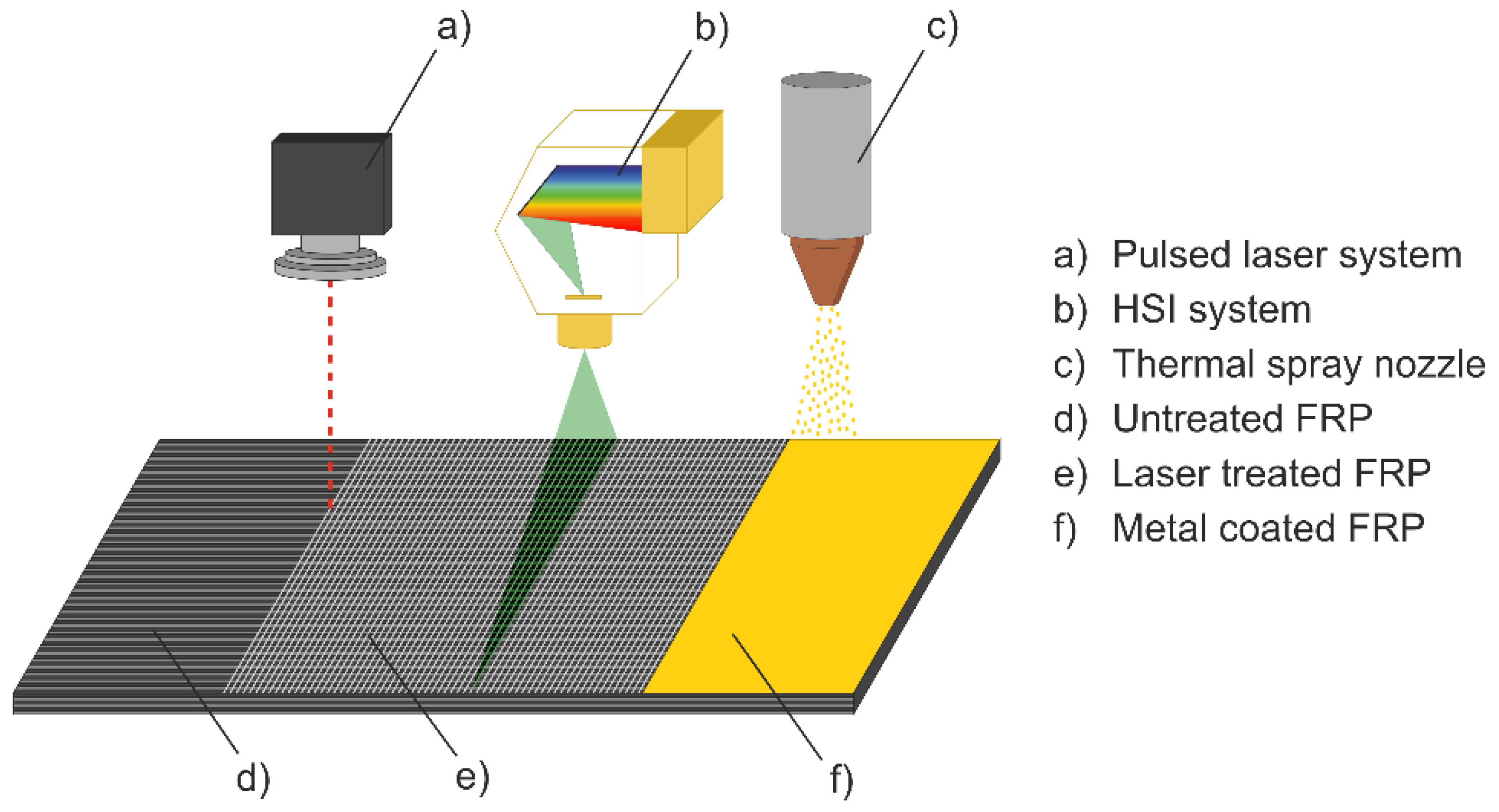
2.2. Process Chain
2.2.1. Laser Pre-Treatment Process
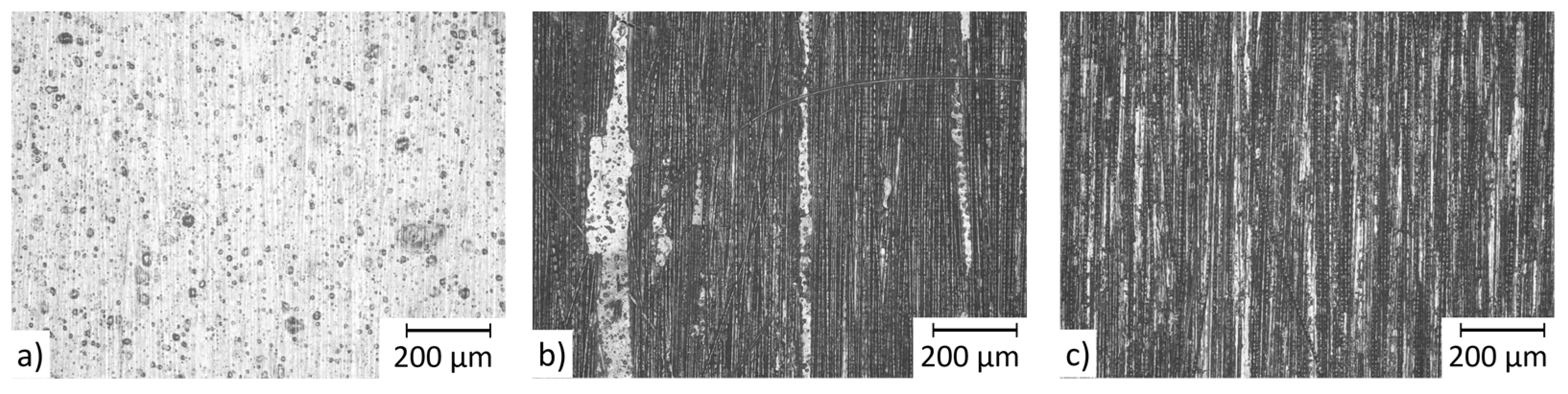
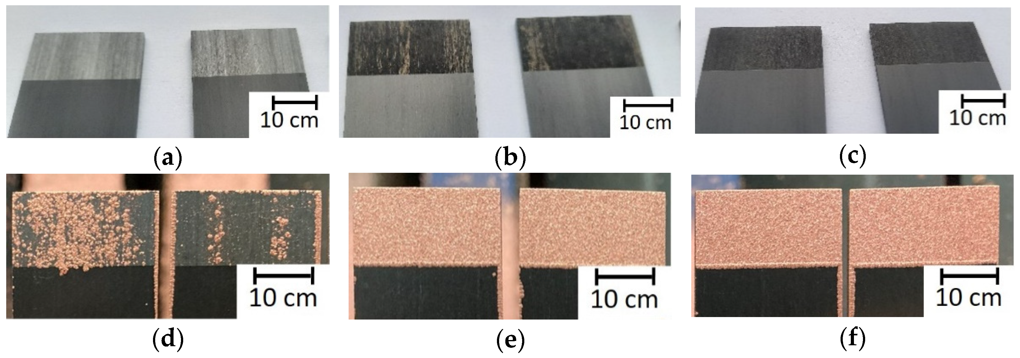
- Insufficient ablation: carbon fibers still covered with plastic matrix.
- Optimal ablation: mostly exposed carbon fibers without damaged fibers.
- Damaging ablation: carbon fibers exposed of plastic matrix and a high amount of broken carbon fibers.
- The ablation pattern of the quality condition insufficient ablation can be assumed to be similar to the ablation pattern that would occur when treating a thick matrix layer.
- In contrast, it can be assumed that the ablation pattern of damaging ablation is similar to the ablation pattern that would occur when treating a thin matrix layer.
2.2.2. Thermal Spraying
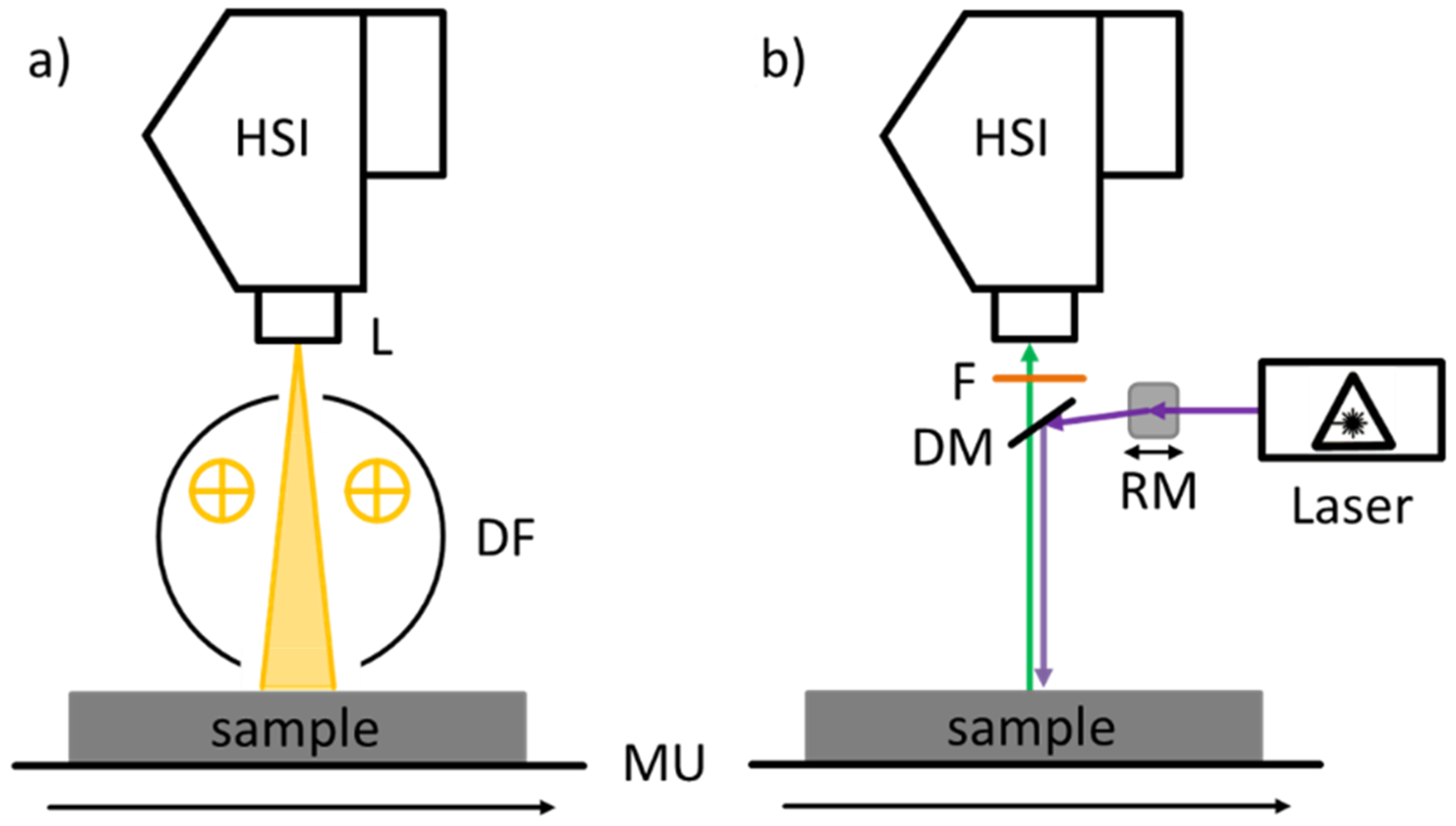
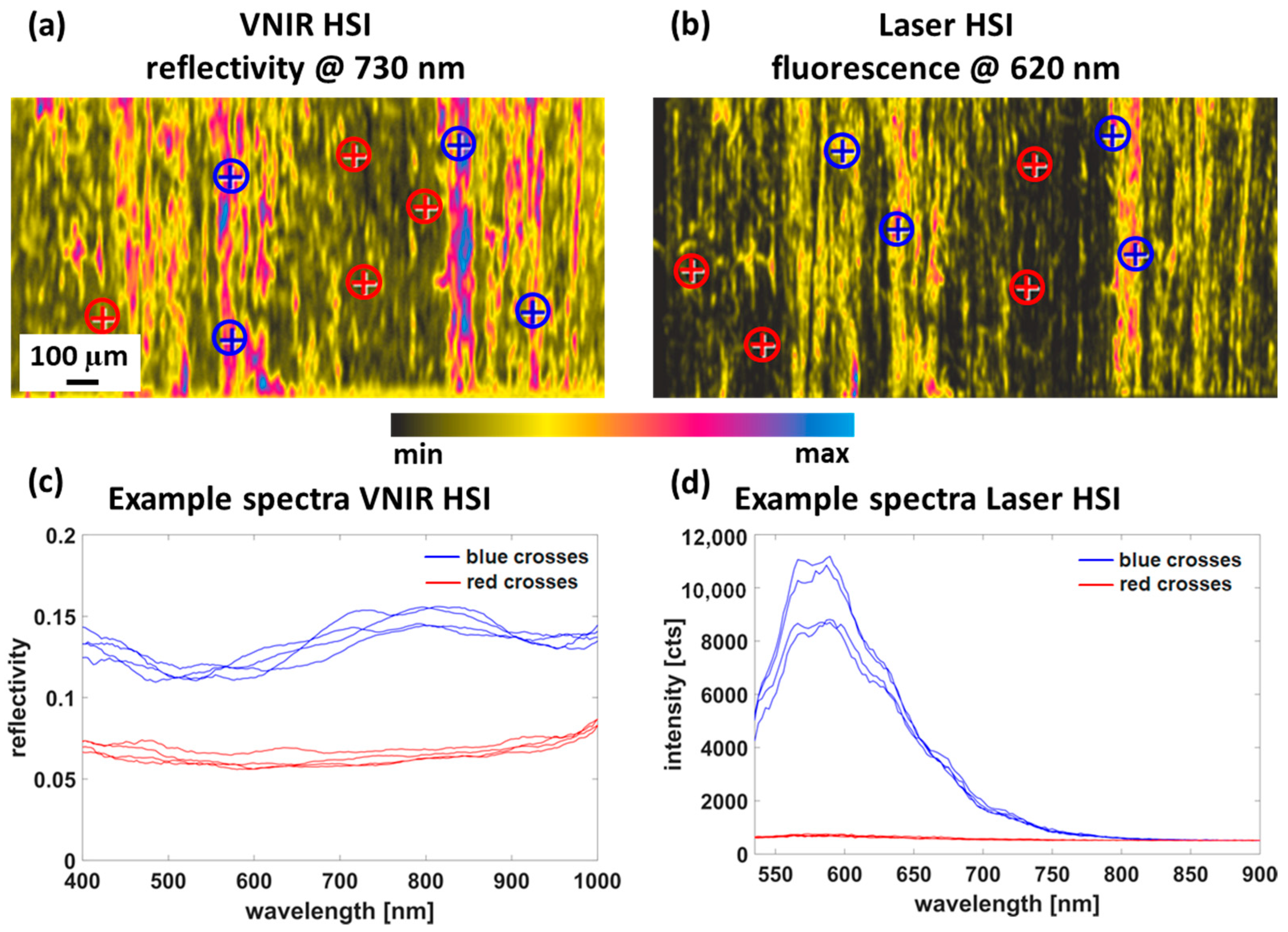
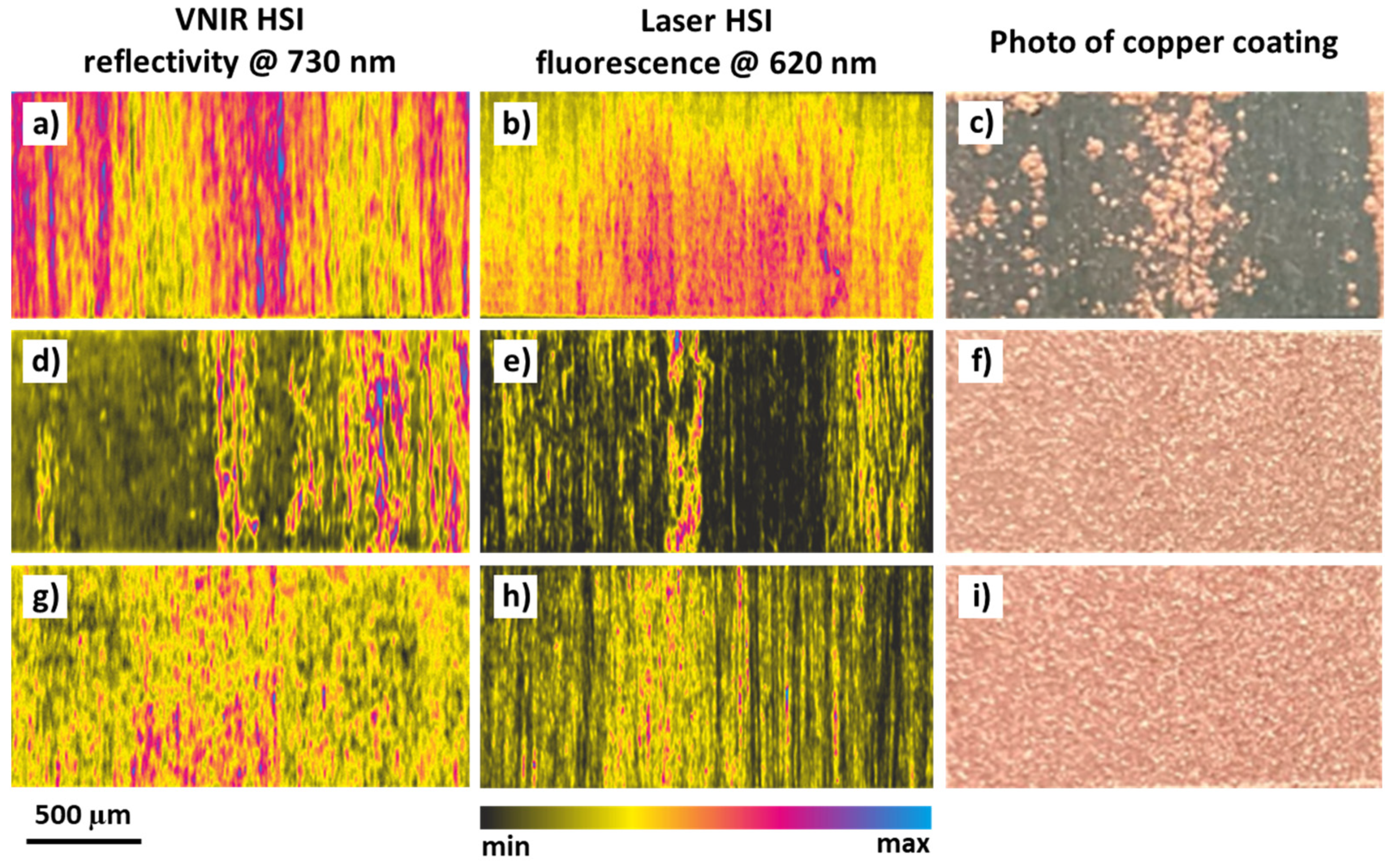
2.2.3. Hyperspectral Imaging
2.2.4. Data Preprocessing and Analysis
2.2.5. Data Evaluation
2.2.6. Optical Characterization Method
3. Results and Discussion
3.1. Laser Structuring Treatment
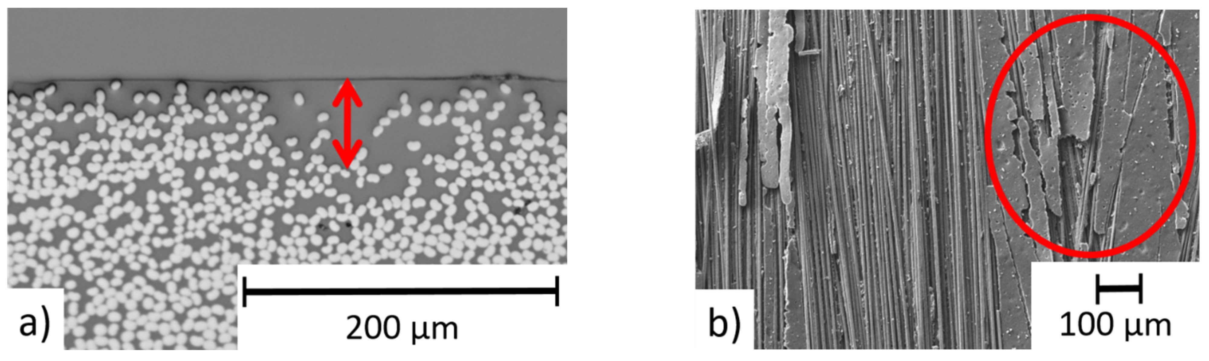
3.2. Coating Deposition
3.3. HSI Measurements of Laser Processed Surfaces
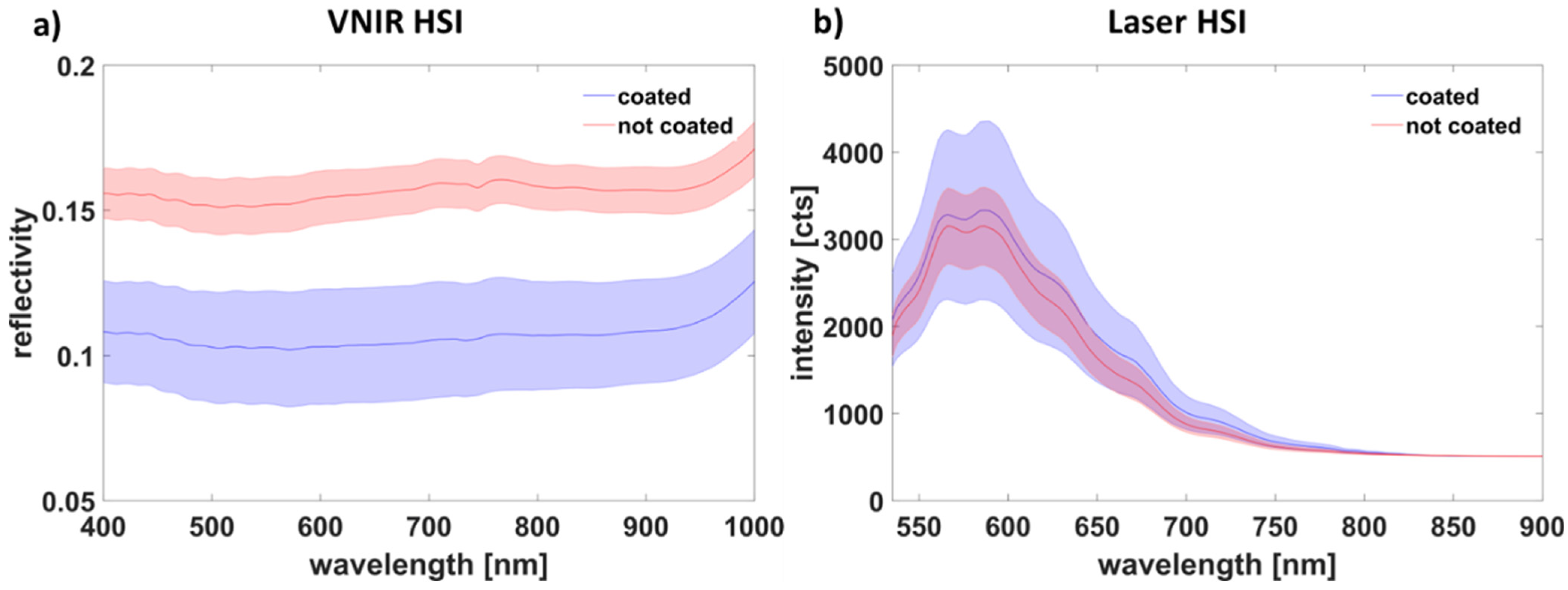
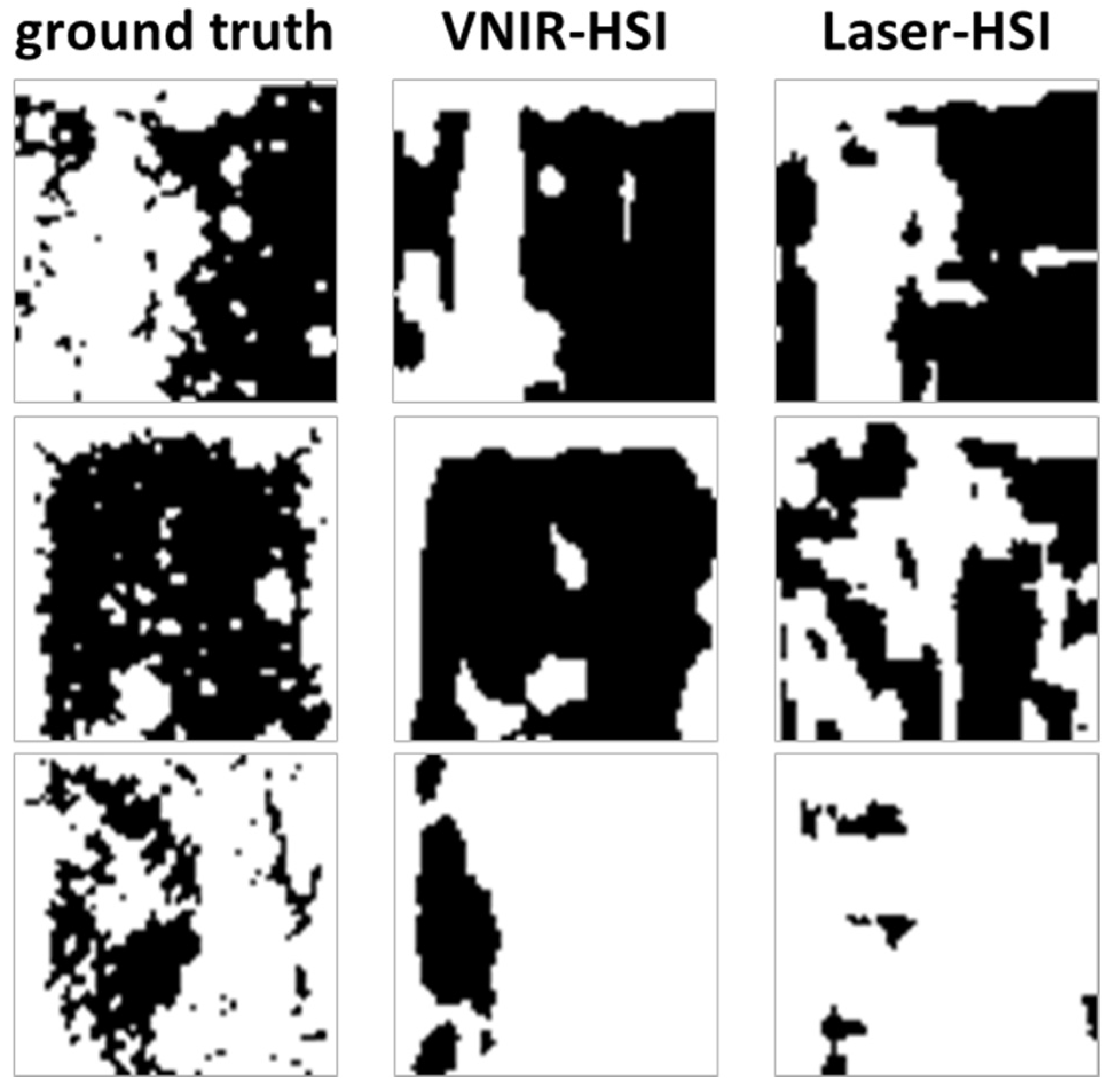
3.4. Data Analysis and Training
4. Conclusions
- An objective and automatic evaluation of the surface quality of CFRP samples after laser pretreatment was developed.
- Prediction of whether a complete coating or a defective and incomplete coating will occur on the specimens is possible with high confidence.
- Prediction of successfully coated areas of a thermal sprayed copper layer are possible with an accuracy of ~80% using developed deep learning models.
- The exact spatially resolved prediction of the coating adhesion is much less accurate and only partially successful.
5. Patents
Author Contributions
Funding
Institutional Review Board Statement
Informed Consent Statement
Data Availability Statement
Acknowledgments
Conflicts of Interest
Appendix A

| Hyperparameter | VNIR | Laser |
|---|---|---|
| Filters f | 16 | 8 |
| Kernel size | 5 | 2 |
| Down sampling steps | 2 | 4 |
| Concatenate | True | False |
| Residuen | True | True |
References
- Schürmann, H. Konstruieren Mit Faser-Kunststoff-Verbunden; Springer: Berlin/Heidelberg, Germany, 2007; ISBN 978-3-540-72189-5. [Google Scholar]
- Qian, D.; Bao, L.; Takatera, M.; Kemmochi, K.; Yamanaka, A. Fiber-reinforced polymer composite materials with high specific strength and excellent solid particle erosion resistance. Wear 2010, 268, 637–642. [Google Scholar] [CrossRef]
- Zhao, Q.; Zhang, K.; Zhu, S.; Xu, H.; Cao, D.; Zhao, L.; Zhang, R.; Yin, W. Review on the Electrical Resistance/Conductivity of Carbon Fiber Reinforced Polymer. Appl. Sci. 2019, 9, 2390. [Google Scholar] [CrossRef] [Green Version]
- Martins, M.; Gomes, R.; Pina, L.; Pereira, C.; Reichmann, O.; Teti, D.; Correia, N.; Rocha, N. Highly Conductive Carbon Fiber-Reinforced Polymer Composite Electronic Box: Out-of-Autoclave Manufacturing for Space Applications. Fibers 2018, 6, 92. [Google Scholar] [CrossRef] [Green Version]
- Gonzalez, R.; Ashrafizadeh, H.; Lopera, A.; Mertiny, P.; McDonald, A. A Review of Thermal Spray Metallization of Polymer-Based Structures. J. Therm. Spray Technol. 2016, 25, 897–919. [Google Scholar] [CrossRef] [Green Version]
- Liu, A.; Guo, M.; Zhao, M.; Ma, H.; Hu, S. Arc sprayed erosion-resistant coating for carbon fiber reinforced polymer matrix composite substrates. Surf. Coat. Technol. 2006, 200, 3073–3077. [Google Scholar] [CrossRef]
- Gebauer, J.; Klotzbach, U.; Lasagni, A.F. Functionalization of fiber-reinforced plastic based on laser micro structuring. In Laser-based Micro- and Nanoprocessing XIII; Klotzbach, U., Kling, R., Watanabe, A., Eds.; SPIE: San Francisco, CA, USA, 2019; p. 11. ISBN 9781510624542. [Google Scholar]
- Boyer, H.; McDonald, A.; Mertiny, P. Flame Spray Deposition of Electrically Conductive Traces on Polymer Substrates for System Integrated Composite Structures. In Proceedings of the Composites 2012, Las Vegas, NV, USA, 21–23 February 2012. COMPOSITES 2012, American Composites Manufacturers Association, Ed. [Google Scholar]
- Machulla, M.; Taghian Dehaghani, S.; Claußnitzer, P.; Scheitz, S.; McDonald, A.; Leyens, C. Thermally Sprayed Coating-Based Heating Systems for Boundary Layer Transition Detection—An Experimental Approach. In Proceedings of the International Thermal Spray Conference, Online, 24–28 May 2021; International Thermal Spray Conference. Azarmi, F., Chen, X., Cizek, J., Cojocaru, C., Jodoin, B., Koivuluoto, H., Lau, Y., Fernandez, R., Ozdemir, O., Salami Jazi, H., et al., Eds.; ASM International: Novelty, OH, USA, 2021; pp. 765–770. [Google Scholar]
- Rezzoug, A.; Abdi, S.; Kaci, A.; Yandouzi, M. Thermal spray metallisation of carbon fibre reinforced polymer composites: Effect of top surface modification on coating adhesion and mechanical properties. Surf. Coat. Technol. 2018, 333, 13–23. [Google Scholar] [CrossRef]
- Robitaille, F.; Yandouzi, M.; Hind, S.; Jodoin, B. Metallic coating of aerospace carbon/epoxy composites by the pulsed gas dynamic spraying process. Surf. Coat. Technol. 2009, 203, 2954–2960. [Google Scholar] [CrossRef]
- Rezzoug, A.; Abdi, S.; Bouhelal, N.; Daoud, S. Metallic Coating for Carbon Fiber Reinforced Polymer Matrix Composite Substrate. Int. J. Mater. Metall. Eng. 2016, 10, 59–64. [Google Scholar]
- Ganesan, A.; Yamada, M.; Fukumoto, M. The Effect of CFRP Surface Treatment on the Splat Morphology and Coating Adhesion Strength. J. Spray Technol. 2014, 23, 236–244. [Google Scholar] [CrossRef]
- Wielage, B.; Paczkowski, G.; Mäder, T.; Rupprecht, C.; Nestler, D. Verschleißschutzschichten auf polymerbasierten Grundwerkstoffen. Tag. Zum 18. Symp. Verb. Und Werkst. 2011, 41, 646–655. [Google Scholar]
- Heckert, A.; Zaeh, M.F. Laser Surface Pre-treatment of Aluminium for Hybrid Joints with Glass Fibre Reinforced Thermoplastics. Phys. Procedia 2014, 56, 1171–1181. [Google Scholar] [CrossRef] [Green Version]
- Koshukow, W.; Krahl, M.; Gude, M.; Götz, P.; Kirchhoff, M. Influence of Laser Surface Treatment for Process-Integrated Joining of Textile Reinforced Thermoplastic Composites to Metal Sheets. In Key Engineering Materials; Trans Tech Publications Ltd.: Bäch, Switzerland, 2017; Volume 742, pp. 366–373. [Google Scholar] [CrossRef]
- Gebauer, J.; Fischer, M.; Lasagni, A.F.; Kühnert, I.; Klotzbach, A. Laser structured surfaces for metal-plastic hybrid joined by injection molding. J. Laser Appl. 2018, 30, 32021. [Google Scholar] [CrossRef]
- Akman, E.; Erdoğan, Y.; Bora, M.Ö.; Çoban, O.; Oztoprak, B.G.; Demir, A. Investigation of the differences between photochemical and photothermal laser ablation on the shear strength of CFRP/CFRP adhesive joints. Int. J. Adhes. Adhes. 2020, 98, 102548. [Google Scholar] [CrossRef]
- Köckritz, T.; Schiefer, T.; Jansen, I.; Beyer, E. Improving the bond strength at hybrid-yarn textile thermoplastic composites for high-technology applications by laser radiation. Int. J. Adhes. Adhes. 2013, 46, 85–94. [Google Scholar] [CrossRef]
- Gebauer, J.; Burkhardt, M.; Franke, V.; Lasagni, A.F. On the Ablation Behavior of Carbon Fiber-Reinforced Plastics during Laser Surface Treatment Using Pulsed Lasers. Materials 2020, 13, 5682. [Google Scholar] [CrossRef] [PubMed]
- Fischer, F.; Kreling, S.; Dilger, K. Surface Structuring of CFRP by using Modern Excimer Laser Sources. Phys. Procedia 2012, 39, 154–160. [Google Scholar] [CrossRef] [Green Version]
- Borengasser, M.; Hungate, W.S.; Watkins, R. Hyperspectral Remote Sensing; CRC Press: Boca Raton, FL, USA, 2007; ISBN 9781420012606. [Google Scholar]
- Dale, L.M.; Thewis, A.; Boudry, C.; Rotar, I.; Dardenne, P.; Baeten, V.; Pierna, J.A.F. Hyperspectral Imaging Applications in Agriculture and Agro-Food Product Quality and Safety Control: A Review. Appl. Spectrosc. Rev. 2013, 48, 142–159. [Google Scholar] [CrossRef]
- Calin, M.A.; Parasca, S.V.; Savastru, D.; Manea, D. Hyperspectral Imaging in the Medical Field: Present and Future. Appl. Spectrosc. Rev. 2014, 49, 435–447. [Google Scholar] [CrossRef]
- Gendrin, C.; Roggo, Y.; Collet, C. Pharmaceutical applications of vibrational chemical imaging and chemometrics: A review. J. Pharm. Biomed. Anal. 2008, 48, 533–553. [Google Scholar] [CrossRef]
- Gruber, F.; Grählert, W.; Wollmann, P.; Kaskel, S. Classification of Black Plastics Waste Using Fluorescence Imaging and Machine Learning. Recycling 2019, 4, 40. [Google Scholar] [CrossRef] [Green Version]
- Gewali, U.B.; Monteiro, S.T.; Saber, E. Machine Learning Based Hyperspectral Image Analysis: A Survey. 2018. Available online: http://arxiv.org/pdf/1802.08701v2 (accessed on 14 April 2022).
- Paoletti, M.E.; Haut, J.M.; Plaza, J.; Plaza, A. Deep learning classifiers for hyperspectral imaging: A review. ISPRS J. Photogramm. Remote Sens. 2019, 158, 279–317. [Google Scholar] [CrossRef]
- Lu, G.; Fei, B. Medical hyperspectral imaging: A review. J. Biomed. Opt. 2014, 19, 10901. [Google Scholar] [CrossRef] [PubMed]
- Lu, B.; Dao, P.; Liu, J.; He, Y.; Shang, J. Recent Advances of Hyperspectral Imaging Technology and Applications in Agriculture. Remote Sens. 2020, 12, 2659. [Google Scholar] [CrossRef]
- Vater, J.M.; Gruber, F.; Grählert, W.; Schneider, S.; Knoll, A.C. Prediction of Coating Adhesion on Laser-Cleaned Metal Surfaces of Battery Cells Using Hyperspectral Imaging and Machine Learning. Coatings 2021, 11, 1388. [Google Scholar] [CrossRef]
- Ronneberger, O.; Fischer, P.; Brox, T. U-Net: Convolutional Networks for Biomedical Image Segmentation. In Medical Image Computing and Computer-Assisted Intervention—MICCAI 2015; Navab, N., Hornegger, J., Wells, W.M., Frangi, A.F., Eds.; Springer International Publishing: Cham, Switzerland, 2015; pp. 234–241. ISBN 978-3-319-24573-7. [Google Scholar]
- Gustke, K.; Gebauer, J.; Drehmann, R.; Lasagni, A.F.; Lampke, T. Enhancement of the Adhesion of Wire Arc Sprayed Coatings on Carbon Fiber-Reinforced Plastic by Surface Laser Structuring. Coatings 2021, 11, 467. [Google Scholar] [CrossRef]
- Chollet, F. Xception: Deep learning with depthwise separable convolutions. In Proceedings of the IEEE Conference on Computer Vision and Pattern Recognition, Honolulu, HI, USA, 21–26 July 2017; pp. 1251–1258. [Google Scholar]
- Li, L.; Jamieson, K.; DeSalvo, G.; Rostamizadeh, A.; Talwalkar, A. Hyperband: A Novel Bandit-Based Approach to Hyperparameter Optimization. J. Mach. Learn. Res. 2017, 18, 6765–6816. [Google Scholar]
- François Chollet. Keras. 2015. Available online: https://keras.io/getting_started/faq/#how-should-i-cite-keras (accessed on 14 April 2022).
- Tieleman, T.; Hinton, G. Lecture 6.5-rmsprop: Divide the gradient by a running average of its recent magnitude. COURSERA: Neural Netw. Mach. Learn. 2012, 4, 26–31. [Google Scholar]
- Kingma, D.P.; Ba, J. Adam: A Method for Stochastic Optimization. 2014. Available online: http://arxiv.org/pdf/1412.6980v9 (accessed on 14 April 2022).


| Quality Condition | Average Power in W | Scanning Speed in mm/s | Hatch Distance in µm | Focal Length in mm | Spot Size in µm |
|---|---|---|---|---|---|
| Insufficient ablation | 1.2 | 1200 | 20 | 160 | 20 |
| Optimal ablation | 4.22 | ||||
| Damaging ablation | 7.23 |
| Current in A | Voltage in V | Spraying Distance in mm | Traverse Speed in m/s | Gas Pressure in MPa | Flow Rate in m3/h |
|---|---|---|---|---|---|
| 80 | 40 | 150 | 1 | 0.6 | 142.6 |
| Data | Precision (P) | Recall (R) | F1 Score | Balanced Accuracy | Mean Intersection over Union (IoU) |
|---|---|---|---|---|---|
| VNIR | 0.954 ± 0.008 | 0.961 ± 0.014 | 0.957 ± 0.012 | 0.795 ± 0.031 | 0.880 ± 0.007 |
| Laser | 0.952 ± 0.009 | 0.944 ± 0.011 | 0.948 ± 0.009 | 0.784 ± 0.039 | 0.860 ± 0.006 |
Publisher’s Note: MDPI stays neutral with regard to jurisdictional claims in published maps and institutional affiliations. |
© 2022 by the authors. Licensee MDPI, Basel, Switzerland. This article is an open access article distributed under the terms and conditions of the Creative Commons Attribution (CC BY) license (https://creativecommons.org/licenses/by/4.0/).
Share and Cite
Gebauer, J.; Gruber, F.; Holfeld, W.; Grählert, W.; Lasagni, A.F. Prediction of the Quality of Thermally Sprayed Copper Coatings on Laser-Structured CFRP Surfaces Using Hyperspectral Imaging. Photonics 2022, 9, 439. https://doi.org/10.3390/photonics9070439
Gebauer J, Gruber F, Holfeld W, Grählert W, Lasagni AF. Prediction of the Quality of Thermally Sprayed Copper Coatings on Laser-Structured CFRP Surfaces Using Hyperspectral Imaging. Photonics. 2022; 9(7):439. https://doi.org/10.3390/photonics9070439
Chicago/Turabian StyleGebauer, Jana, Florian Gruber, Wilhelm Holfeld, Wulf Grählert, and Andrés Fabián Lasagni. 2022. "Prediction of the Quality of Thermally Sprayed Copper Coatings on Laser-Structured CFRP Surfaces Using Hyperspectral Imaging" Photonics 9, no. 7: 439. https://doi.org/10.3390/photonics9070439