Article

Multiplexed Holographic Combiner with Extended Eye Box Fabricated by Wave Front Printing

1
Department of Electrical Engineering and Information Technology, Karlsruhe Institute of Technology, 76131 Karlsruhe, Germany
2
Research and Advance Engineering, Robert Bosch GmbH, 71272 Renningen, Germany
*
Author to whom correspondence should be addressed.
Photonics 2022, 9(6), 419; https://doi.org/10.3390/photonics9060419
Submission received: 23 May 2022 / Revised: 8 June 2022 / Accepted: 13 June 2022 / Published: 15 June 2022
(This article belongs to the Special Issue Materials, Methods and Models for Holographic Optical Elements)

Abstract

:
We present an array-based volume holographic optical element (vHOE) recorded as an optical combiner for novel display applications such as smart glasses. The vHOE performs multiple, complex optical functions in the form of large off-axis to on-axis wave front transformations and an extended eye box implemented in the form of two distinct vertex points with red and green chromatic functions. The holographic combiner is fabricated by our extended immersion-based wave front printing setup, which provides extensive prototyping capabilities due to independent wave front modulation and large possible off-axis recording angles, enabling vHOEs in reflection with a wide range of different recording configurations. The presented vHOE is build up as an array of sub-holograms, where each element is recorded with individual optical functions. We introduce a design and fabrication method to combine two angular and two spectral functions in the volume grating of individual sub-holograms, demonstrating complex holographic elements with four multiplexed optical functions comprised in a single layer of photopolymer film. The introduced design and fabrication process allows the precise tuning of the vHOE’s diffractive properties to achieve well-balanced diffraction efficiencies and angular distributions between individual multiplexed functions.

1. Introduction

The field of augmented reality (AR) has received increasing attention in recent years. Being already established for specific professional use-cases, AR technology is expected to extend into the high volume consumer market in the near future [1]. In contrast to virtual reality, AR displays superimpose an image into the user’s field of vision, augmenting the user’s real-world view without obstructing it. As a result, excellent see-through capabilities, a comfortable weight for everyday wear and a high quality of the projected image are key requirements of future consumer AR glasses. Given the increased overall weight that is associated with waveguide-based systems, retinal projection displays represent a promising approach for consumer AR glasses. As a consequence, combiner optics for retinal projection systems, which perform complex optical functions while maintaining excellent transparency are sought after [2,3]. Apart from high transparency, demands for optical combiners include full color reconstruction, a large field of view (FoV) and an extended eye-box size. A consistent challenge is the concurrent optimization of eye-box size and FoV, as both parameters are linked in traditional optical systems by a constant factor; the so-called étendue [4]. In general, large étendues are desirable to achieve both a sufficient eye-box size and a large FoV; however, large étendues also lead to large device form factors, which are undesirable for consumer glasses. To overcome this trade-off, current retinal projection displays have introduced different measures, including pupil duplication [5,6,7] and pupil steering [8,9,10]; however, both methods further increase the complexity of the employed combiner component.
A promising approach to meet the outlined requirements of future AR combiners are volume holographic optical elements (vHOEs) fabricated by means of holographic wave front printing. Diffractive elements based on volume holograms are characterized by a high angle and wavelength selectivity due to their characteristic Bragg gratings [11,12]. As a result, volume holograms achieve high diffraction efficiencies for reconstruction in Bragg configuration paired with excellent transmittance properties for deviating replay configurations [11,13,14]. In addition to that, holographic wave front printing has proven itself to be a feasible technology to realize holograms with complex optical functions, i.e., to fabricate vHOE-based freeform optics as demonstrated by Jang et al. [15]. vHOEs fabricated by holographic wave front printing are array-based structures build up by single holographic elements, so-called Hogels. Each Hogel comprises a permanent volume diffraction grating with a sinusoidal index modulation, based on the interference pattern exhibited by a photosensitive holographic material during the recording sequence. Single Hogels are recorded by two coherent recording wave fronts, which are adaptively shaped by means of spatial light modulators (SLMs) and brought to interference in the material’s volume; resulting in digitally designed wave front characteristics that are transformed into physical holographic structures. Consequently, wave-front-printed vHOEs enable the realization of complex optical functions and provide new opportunities in the design of optical systems. In particular, the combination of angular and spectral multiplexed vHOEs or the recording of adjacent Hogels contributing to different optical functions enables the realization of suitable AR combiners in a single holographic layer. Single-layer combiners are a solution to optical distortions such as ghosting and stray light, which remain a challenge in multi-layer-based combiners.
Over the years, numerous holographic wave front printers have been presented [16,17,18,19,20]. Notably, a rudimentary SLM-based wave-front printer setup has been implemented by Miyamoto et al. [21] to record vHOEs in reflection and to reconstruct three-dimensional scenes under white light. A phase-only SLM in combination with a sophisticated algorithm based on complex amplitude modulation has been presented by Nishii et al. [22]. Regarding holographic combiner technology Ramsbottom et al. [23] evaluated hologram-based combiners for head-up display applications. Furthermore, holographic combiners for retinal projection displays have been presented by Ando et al. [24] and Takahashi et al. [25].
In previous publications, we have introduced an extended holographic wave front recording setup with two phase-only SLMs, which enable the wave front shaping of both the object and reference wave front to record vHOEs in reflection [26,27]. Our immersion-based recording scheme allows the recording of vHOEs with large off-axis angles, which is critical for the recording of optical combiners for retinal projection systems [28].
In this article, we present the recording of an holographic combiner for AR applications based on the superposition of multiple optical functions in one single layer of holographic photopolymer. The resulting vHOE projects two distinct single eye boxes, realizing a pupil duplication scheme. Both eye-boxes are recorded, employing two lasers emitting in the red and green spectral regime; resulting in a multiplexed vHOE that is build up of individual Hogels, each combining two angular and two spectral functions. In the following, we outline the design and fabrication process to realize the presented vHOE-based combiner. The design process introduces the principle for holographic wave front printing with individually modulated recording wave fronts including an overview of our employed recording setup. The fabrication process consists of a monochromatic recording material evaluation followed by a polychromatic optimization to derive suitable recording parameters. Finally, the fabrication of the holographic combiner according to the determined recording parameters is outlined, and its optical characteristics are discussed based on evaluations of the vHOE’s diffractive properties.

2. Materials and Methods

The principle of holographic wave front printing is based on the recording of single holographic elements, introduced as Hogels. Hogels are recorded in a sequential, step-wise scheme and positioned adjacently to form an array-based vHOE. The recording of individual sub-holograms is based on the interference of two coherent, spatially modulated wave fronts, which interfere in the volume of a photosensitive material to form a three-dimensional diffraction grating. The recorded holographic function can be reconstructed by illuminating the Hogel with a characteristic wave front corresponding to the recording configuration. The recording wave fronts are modulated according to digitally designed phase patterns, and employed on SLMs to shape the recording beams by means of diffraction; thus, enabling each Hogel to be recorded with an individual optical function. A key characteristic of our employed holographic recording setup is the modulation of both the object as well as the reference recording wave front. A schematic representation of the hologram design process, given by the employed phase patterns as well as the recording in a sequential fashion, is presented in Figure 1. Furthermore, microscope images of the recorded vHOE under phase-contrast, dark-field and bright-field configuration are outlined.
In the following section, the design and fabrication process for the presented holographic combiner is outlined. The phase pattern generation scheme and the employed holographic recording setup are presented. Furthermore, the process to determine suitable recording parameters for multiplexed holographic structures is outlined.

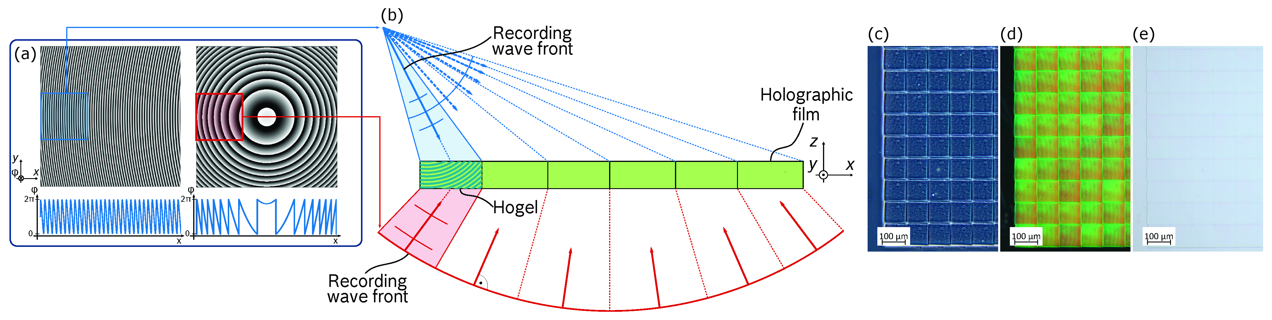
2.1. Phase Pattern Generation

The phase patterns modulating each hologram’s object and reference wave are calculated as two-dimensional diffraction patterns; applied to the respective SLM via an array of 8-bit gray-scale values corresponding to each individual SLM pixel. The resulting phase pattern has a sinusoidal shape; generating a continuous phase function across the SLM’s surface, which is given by
Ψ ( x , y ) = A 1 2 + 1 2 cos ( k ̲ x x + k ̲ y y + Φ ( x , y ) ) .
In this equation, x and y correspond to the SLM’s individual pixel coordinates, while A is a scaling factor for the pattern. The desired optical function for the recording wave front is integrated in the argument of the cosine-function. k ̲ x and k ̲ y represent the local spatial frequency components, employed as lateral wave vector component offset, while Φ ( x , y ) comprises the hologram’s scalar phase function. In our setup Zernike polynomials [29] paired with point source phase expressions are employed to shape the recording wave front’s phase. The resulting phase pattern operates as a surface hologram, which transforms the recording beam to the desired wave front. The modulated object and reference wave front are relayed through the optical system to the recording plane, where an interference pattern is formed in the volume of the holographic film; forming a diffraction grating in accordance with the two recording wave front’s characteristics. A schematic outline of two phase patterns resulting in a vHOE’s global phase function, as well as sub-sections of the phase patterns corresponding to an individual Hogel are presented in Figure 1a.

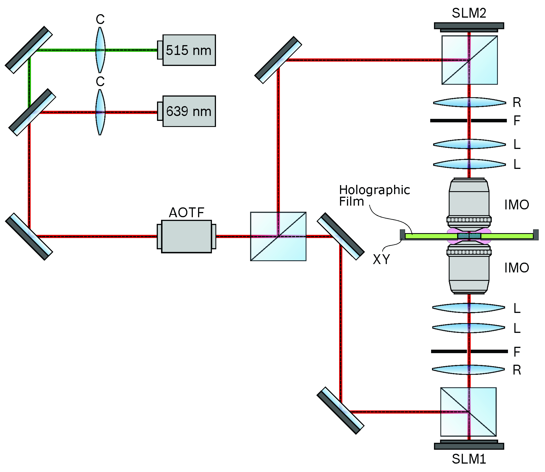
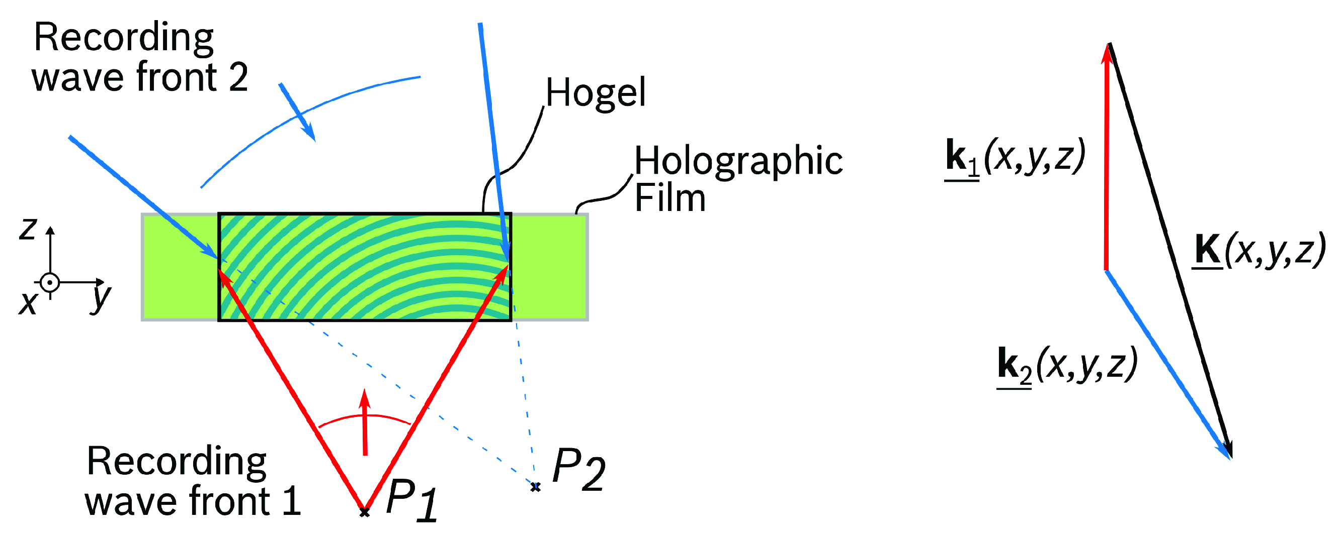
2.2. Wave Front Recording Setup

The wave front recording setup employs two optical light sources implemented as single-frequency diode-pumped solid-state lasers at 515 nm (Cobolt Fandango TM, 150 mW) and 639 nm (Lasos, RLK 40150 TS, 150 mW), respectively. The beams of both lasers are collimated using collimation lenses (C) and aligned on a common optical axis by means of a dichroic mirror. The resulting common beam is relayed to an acousto-optical filter (AOTF), which allows the tuning of both the beam’s optical power as well as the pulse length to precisely control the vHOE’s recording parameters. The object and reference beams are generated by evenly splitting the AOTF-modulated beam and relaying the two resulting beams to the respective SLMs. In the employed recording setup both the object and reference wave are individually shaped by means of two phase-only SLMs (Holoeye, GAEA-2). The main optical system, accommodating the recording wave front propagation, is implemented in an on-axis configuration with both SLMs being positioned at the opposite ends of two symmetrical optical systems (OS1, OS2), which are aligned on a common optical axis. The recording plane with the holographic film is positioned in the center of the setup between OS1 and OS2, with its surface normal being aligned in parallel to the common optical axis. The holographic film is laminated on a glass substrate and mounted on a high-precision, two-dimensional translation stage (Alio, AIOLM-35000E-350-XY, XY), which allows the controllable positioning of single Hogels with an accuracy of ∼ 10 n m . Subsequently, large-area vHOEs are fabricated by adjacently recording multiple Hogels in an array-based stepwise fashion. A schematic of the employed recording setup is outlined in Figure 2.
The symmetrical optical systems OS1 and OS2 are each realized as two telemetric 8-f systems, relaying the modulated recording wave front from the SLM plane to the recording plane in the volume of the holographic film. Each 8-f system is set up by means of two consecutive 4-f systems with a large total magnification of 1/53. OS1 and OS2 are implemented using a camera lens (Rodenstock, Rodagon 135 mm, R), a microscope objective (Zeiss LD LCI Plan-Apochromat 63x/1.2, IMO) as well as multiple achromatic lenses (L) used for collimation and beam relaying. A spatial frequency filter (F) with an adjustable aperture of approximately 5 m m × 5 m m is implemented in the Fourier plane of the first consecutive 4-f system, enabling the on-axis separation of the SLM’s first diffraction order from the zeroth diffraction order as well as other higher diffraction orders. The optical system’s large magnification results in a small spot size paired with a large magnification of the propagating wave front’s off-axis angle.
Large off-axis recording configurations are enabled by the reversely illuminated, immersion-based plan-apochromat microscope objective (IMO) with a numerical aperture of NA = 1.2 , positioned as final component of OS1 and OS2. The interface between the microscope objective and the holographic film is immersed in glycerol with a refractive index of n = 1.47 , enabling wave front propagation with angles larger than the angle of total internal reflection at a glass/air interface.

2.3. Recording Parameters Determination

The vHOE is recorded in a development grade, photopolymer-based holographic film (Bayfol® HX TP*) by Covestro [30] with a photopolymer thickness of 16 μ m and a protective polyamide layer of 60 μ m . During the recording process, the interference pattern generated by the two recording wave fronts results in a photopolymerization-based modulation of the local refractive index in the volume of the holographic film. Monomers rearrange in a diffusion-based process and the recording wave front’s characteristics are manifested inside the holographic film’s volume in the form of a three-dimensional diffraction grating.
The diffractive properties, especially for multiplexed gratings, can be described by the parallel stacked mirror (PSM) model [31]. Applying the PSM model, the hologram is modeled as an infinite stack of parallel mirrors, each modeled by a discontinuity in the permittivity profile. Diffraction at the holographic gratings is modeled using only Fresnel reflection. The PSM model is in good agreement with the coupled wave theory of Kogelnik [32], which is established for single function, sinusoidal volume holographic gratings. However, the PSM model is more suited to model polychromatic, spatially multiplexed volume phase gratings at Bragg resonance, which is achieved by the N-PSM model; an extension of the PSM model that takes N grating planes to model each respective multiplexed grating. Further details on the PSM and N-PSM model are outlined in [31,33]. The N-PSM model assumes no significant cross-reflections between the grating planes of subsequent holographic functions. As a result, the total diffractive response of a polychromatic volume phase grating, consisting of M spectral functions, at near Bragg resonance is given by
η = m = 1 M η m = m = 1 M 1 c s · κ m 2 k = 1 N κ m , k 2 c s , k · tanh 2 d 1 c r k = 1 N κ m , k 2 c s , k .
Comprising the mth recording wavelength, the kth signal wave, the coupling coefficient κ and the parameters c r and c s given by
κ = π · n 1 , m λ c ; c r = cos ( θ c ) 2 α · cos ( θ r ) ; c s = cos ( θ c ) 2 α · cos ( θ r ) ,
where θ r is the reference recording angle and θ c the applied reconstruction wave’s angle. Further, d represents the thickness of the holographic film, n 1 , m the amplitude of the respective index modulation and α = λ c / λ r the relation between the reconstruction wavelength λ c and the recording wavelength λ r .
For N , the lossless polychromatic diffraction characteristics of the mth wavelength can be described by
η m = tanh 2 d κ m cos ( θ c ) .
With constant values for the parameters of θ c , λ c and d, the achievable diffraction efficiency of an hologram reconstructed under Bragg configuration is in practice mainly adjusted by tuning the film’s index modulation during the holographic recording process. Subsequentially, the index modulation can be described by [34]
n 1 ( E ) = n max ( 1 e γ ( E E 0 ) ) .
The index modulation is controlled by the recording energy E, given by the product of the employed optical power and the exposure time. E 0 describes the minimum initiation energy below which no photopolymerization occurs inside the holographic medium. The coefficients n max and γ describe the maximum achievable index modulation and the slope of n 1 ( E ) in the linear region. The theoretical diffractive characteristics of polychromatic holograms consisting of holographic functions in the red and green spectral regime for different recording scenarios are outlined in Figure 3. The figure displays relative diffraction efficiencies based on Equation (4) for individual holographic functions, assuming different fractions of the maximum index modulation n max of a given holographic material has been consumed during the recording process. The figure provides an overview for various recording configurations.
According to Figure 3, the diffractive characteristics of a polychromatic hologram can be adjusted by tuning the applied index modulation with respect to the recording parameters. Subsequentially, suitable recording parameters to achieve equally large diffraction efficiencies for spectrally multiplexed functions, as well as angular multiplexed functions are determined performing a three step process. First, the holographic film’s characteristics for monochromatic exposure for holograms in the red and green spectral range are evaluated and the maximum achievable index modulation n max is derived, assuming n max = n max , green + n max , red and n max , green / λ green = n max , red / λ red . Hereby, the AOTF employed as an optical shutter in the recording setup allows the modulation of both optical power and exposure time during individual recording sequences. Second, the resulting index modulation values act as parameter basis to record spectrally multiplexed holographic structures in the red and green spectrum in a sequential scheme. Multiple holograms with varying recording parameters are fabricated and a multi-dimensional linear interpolation is applied to obtain recording parameters for maximum, evenly distributed diffraction efficiencies between both spectral functions. Third, step two is repeated for spatially and spectrally multiplexed holograms, taking into account the results of step one and two.
The diffractive properties of holograms fabricated over the course of this work are characterized using a dedicated experimental platform. The characterization setup contains a broadband tungsten-halogen based optical source (Thorlabs, SLS201L) paired with an optical spectrophotometer (Ocean Insight, HR4PRO-XR-ES) as well as multiple, high-precision motorized rotational actuators. Using the motorized actuators, the holographic specimen’s spectral properties are evaluated under several well-defined incident angles. The spectrophotometer is positioned either behind or in front of the hologram. Being positioned behind the hologram, the spectrophotometer forms a common optical axis with the optical source and the specimen, which allows measurements of the hologram’s chromatic transmission. The relative diffraction properties of the hologram can be evaluated by analyzing the specimen’s transmission spectrum against a reference transmission spectrum. The measurement scheme to obtain a hologram’s relative diffraction efficiency η rel from the chromatic transmission signal is outlined in Figure 4. The hologram’s transmission signal is normalized using the transmitted signal of bleached photopolymer film as a reference. Additional, broadband deviations in the normalized signal can be attributed to absorption as well as stray light effects in the photopolymer material and are removed using a baseline correction. If the spectrophotometer is positioned in the same half-sphere as the optical source, the Bragg configuration of the reflection hologram as well as deviations from it can be evaluated by directly measuring the optical intensity at a given configuration.

3. Results and Discussion

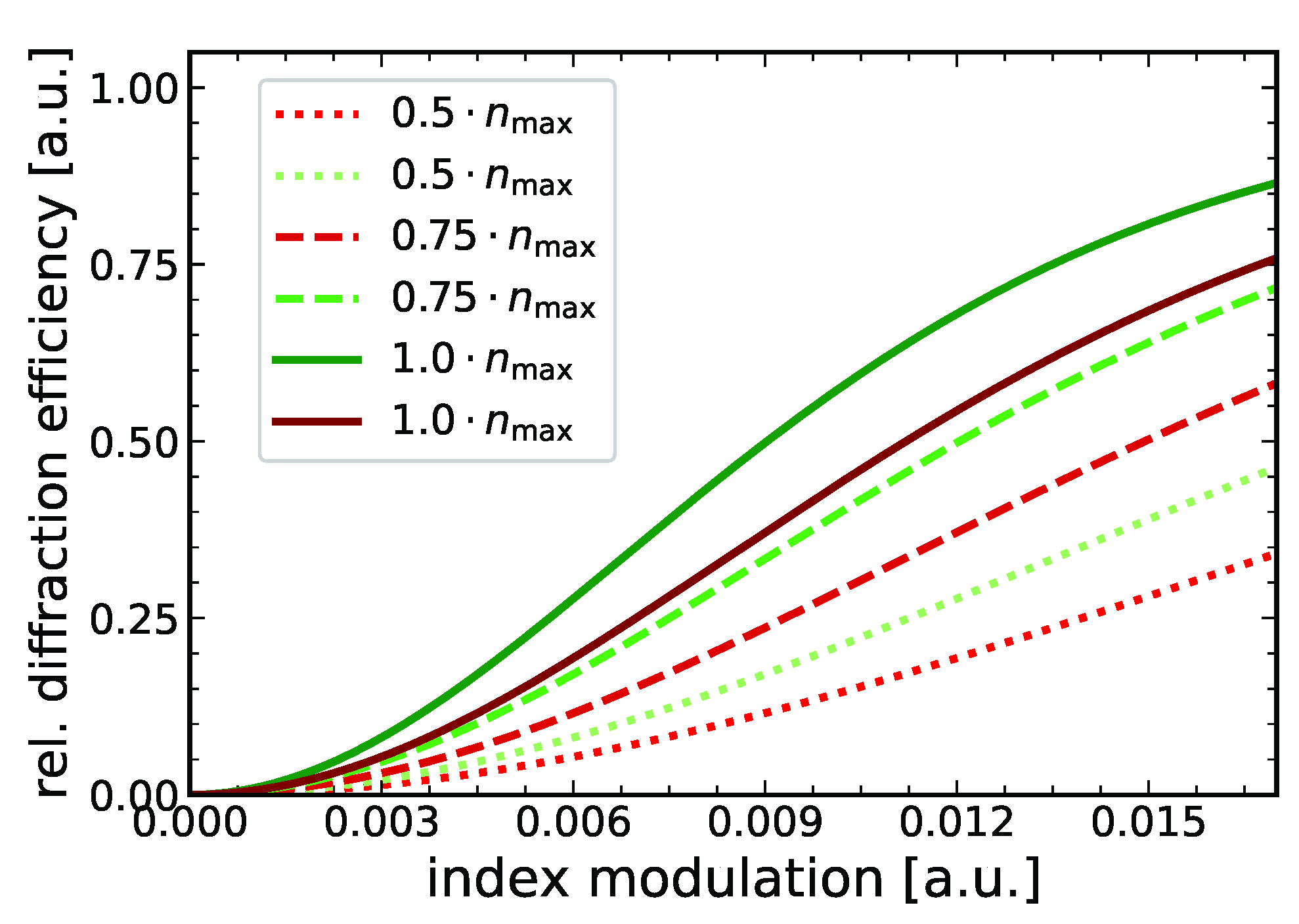
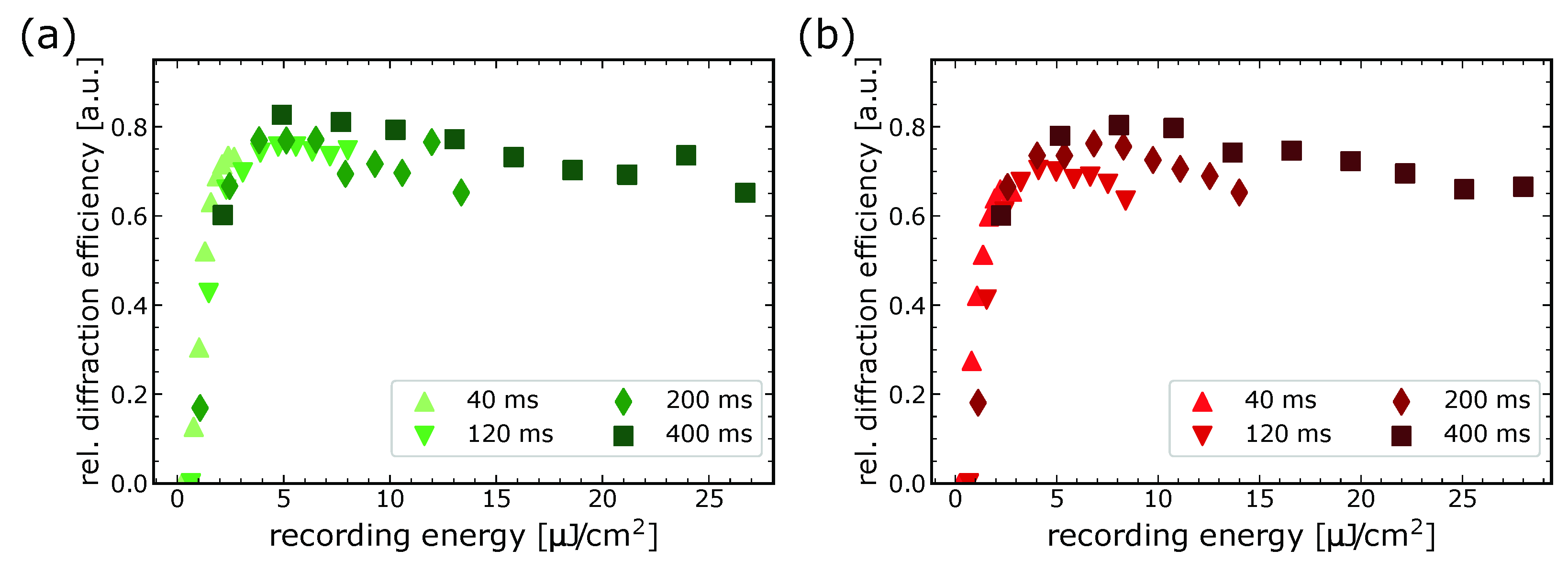
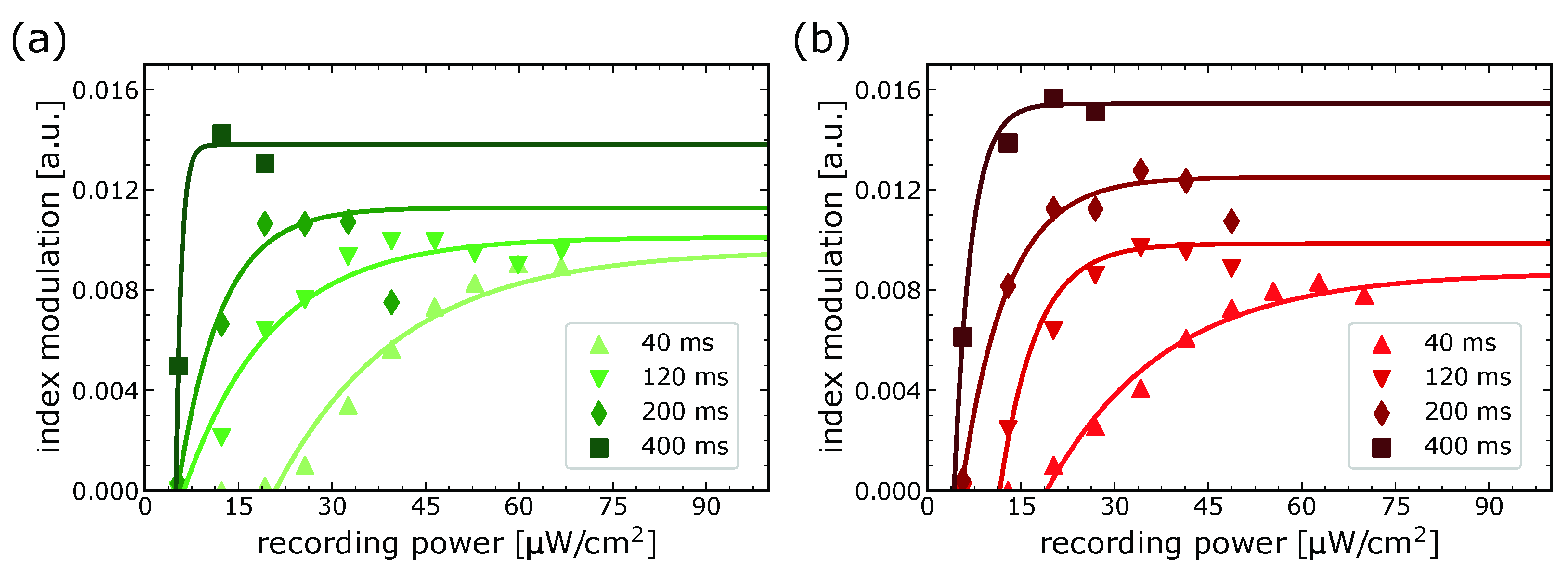
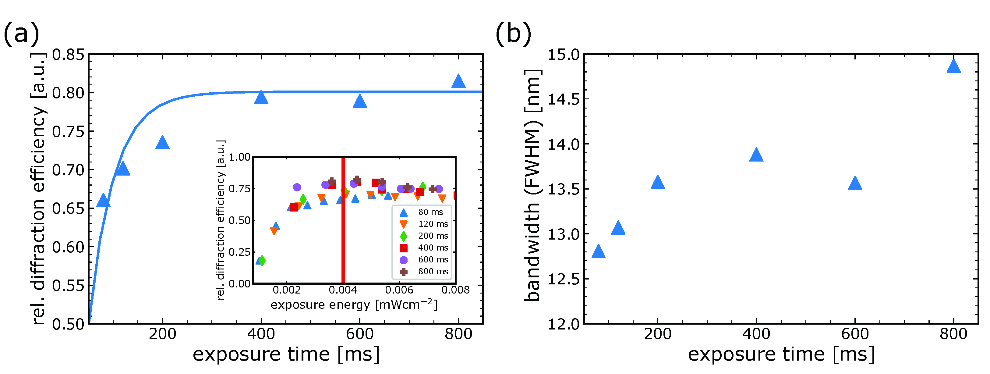
3.1. Monochromatic Recording Parameters

In the first subsection the maximum achievable index modulation n max for monochromatic holograms at λ = 639   n m and λ = 515   n m is derived. This is achieved by recording several holograms with varying recording parameters using the automated recording scheme of our wave front printer setup. Several temporal series of different exposure times, each containing multiple vHOEs with parameter runs of the recording power are fabricated. Each vHOE is build up as an array-based structure of multiple Hogels placed in an intermittent fashion and with a squared feature size of approximately 100 μ m × 100 μ m . Thus, the displayed power densities and exposure times correspond to the employed recording parameters for an individual Hogel.
The measured relative diffractive efficiencies for the exemplary temporal series of t { 40 , 120 , 200 , 400 } ms are outlined in Figure 5 and subsequentially, the resulting index modulations according to Equation (5) are outlined in Figure 6 for both the green spectral function (a) as well as the red spectral function (b). The corresponding fit parameters are presented in Table 1.
Maximum relative diffraction efficiencies of up to η rel , green = 83.9 % and η rel , red = 80.5 % and maximum index modulations of n max , green = 0.0154 and n max , red = 0.0138 are achieved for the green and red spectral functions, respectively. Overall, the outlined curves in Figure 5 demonstrate the expected behavior, containing a threshold initiation energy, followed by a strong increase in the relative diffraction efficiency and a transition into the saturated region.
Particular noteworthy observations from Figure 5 are an exposure time sensitivity of the employed photopolymer material to absorb the recording energy, which results in a dependence of the achievable relative diffraction efficiency, as well as an efficiency diminishing effect for holograms being recorded with high energies and long exposure times.
The observed time sensitivity of the holographic material limits the achievable diffraction efficiency, especially for short exposure times. Figure 7a outlines the measured relative diffraction efficiency for holograms of several temporal series, all recorded with an equal energy level of 0.004 m W c m 2 . The outlined graph is fitted to a function with exponential characteristic, indicating an exposure time τ = 72.7 m s , which is required to achieve 80 % energy absorption of the photopolymer material during a recording sequence. The effect can not be compensated by further increasing the optical power as the photopolymer is already in the saturated regime for the investigated energy, as can be observed in the inset of Figure 7a with the evaluated energy level highlighted as red vertical bar. The decrease in the relative diffraction efficiency for holograms exhibiting long exposure times can be attributed to an increase in the hologram’s bandwidth, which occurs due the dynamic formation of the diffraction grating during the recording process in photopolymer materials. In particular during long exposures, the photopolymer begins to shrink during the early stages of grating formation while still being illuminated by the recording beams. As a result, the already established holographic gratings of the active photopolymer, which are still in a process of dynamic grating formation, begin to diffract light from the illuminating recording beams under slightly deviating angles due to the shrunken photopolymer. Continuous grating formation under the described condition alters the hologram’s initial optical properties, leading to an increase in bandwidth paired with a decrease in the maximum achievable diffraction efficiency. Figure 7b outlines the resulting hologram bandwidth, displayed as full width at half maximum (FWHM) at an equal energy level as outlined in Figure 7a.

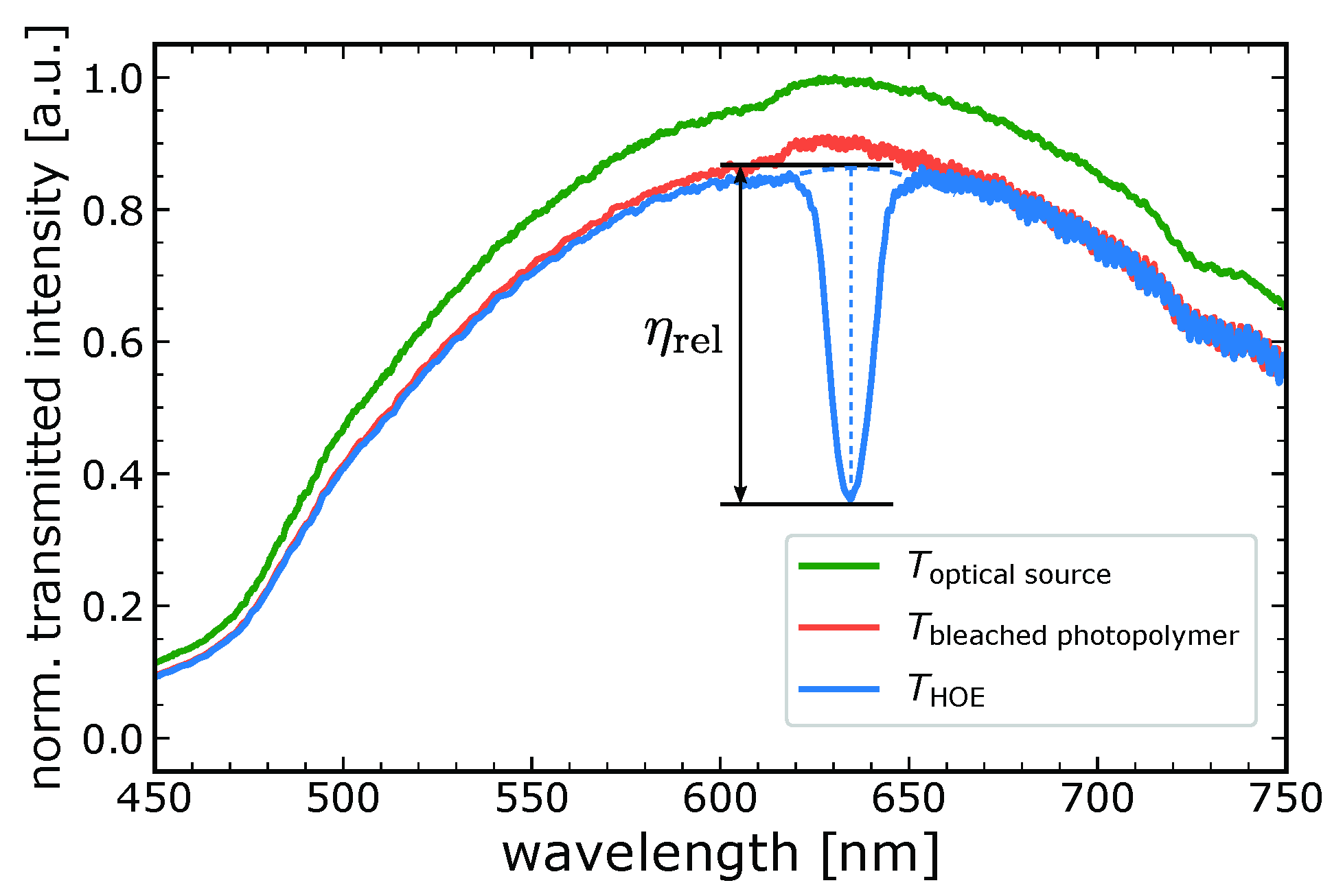
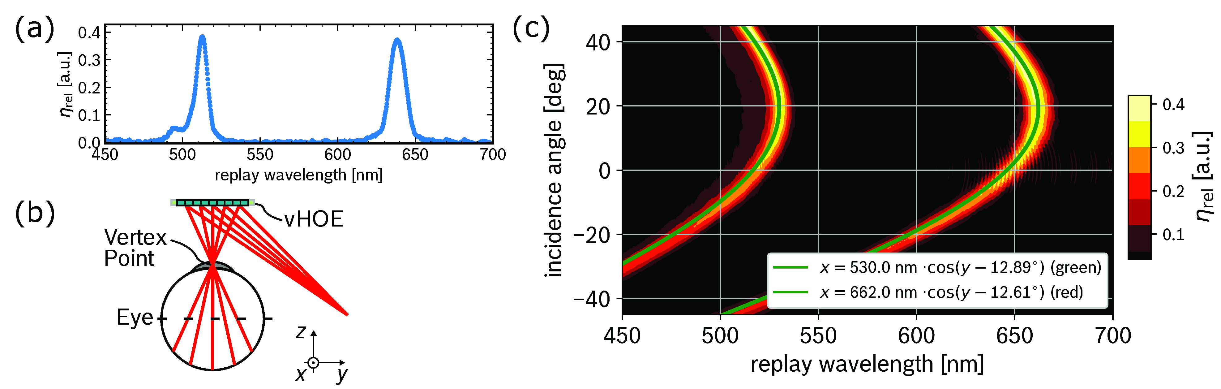
3.2. Spectral Multiplexing

Recording of individual, spectrally multiplexed Hogels is performed in a sequential fashion, whereby the red recording beam followed by the green recording beam illuminate the same Hogel area on the holographic film. In order to derive suitable recording parameters that combine both a high individual relative diffraction efficiency and an even distribution of the efficiency per spectral function, several temporal series of recorded holograms paired with sweeps of the recording power are carried out using our automated recording scheme. Hereby, the parameters derived in Section 3.1 provide the foundation to estimate promising parameter combinations, leading especially to long exposure times at low optical powers, which are used as starting points for the recording of multiplexed holograms. In detail, the parameter sweeps range from P g r e e n [ 5.3 , 66.8 ] μ W c m 2 , P r e d [ 5.6 , 70.0 ] μ W c m 2 , t g r e e n [ 200 , 800 ] ms and t r e d [ 200 , 800 ] ms. Combining multiple optical functions in a single holographic structure results in a complex grating that contains multiple sinusoidal modulation functions. The resulting volume grating is characterized by a superimposed index modulation function, which reduces the achievable diffraction efficiency of individual optical functions compared to the non-multiplexed case. The actual achievable diffraction efficiency depends on the spectral properties as well as the wave vector distribution of the multiplexed functions. To approximate the relative diffraction efficiencies of both spectral functions a piecewise, multi-dimensional linear interpolator is employed based on the triangulation of all recording parameters and their corresponding measured relative diffraction efficiencies. The interpolant uses Delaunay triangulation to estimate the resulting diffraction efficiency based on a set of given input recording parameters; allowing the evaluation of promising diffraction efficiencies for intermediate recording configurations. As a result, a function of merit is defined, which calculates local minima for Δ η = | η g r e e n η r e d | for specific recording configurations in the known recording parameter space. The highest relative diffraction efficiencies satisfying the local minima criteria are outlined in Table 2 with an estimated diffraction efficiency η M dim , interp of approximately 39.3 % and 41.6 % for the green and red chromatic functions, respectively. The linear interpolator-based results are in good conformity with the measured relative diffraction efficiencies η rel , meas of 39 % and 41 % , respectively, as outlined in Table 2. Additionally, the expected diffraction efficiencies based on the monochromatic recording parameters obtained in Section 3.1 and the N-PSM model introduced in Section 2.3 are calculated. The index modulations for the multiplexed gratings are estimated, employing the obtained recording parameters from the multi-dimensional interpolator as input for the derived index fit functions from the monochromatic evaluation outlined in Table 1. First, an independent consumption of the available index modulation for the first recording pulse is assumed, which leads to a relative diffraction efficiency of 38.6 % for the red spectral function, according to the N-PSM model given by Equation (4). For the second recording pulse a reduced index modulation is obtained by assuming that the index budget is first consumed by the red spectral function, whereas the remaining index budget is utilized by the green spectral function. The index modulation for the green spectral function is obtained via the index relation introduced in Section 2.3, leading to a relative diffraction efficiency of 37.5 % , which is in good consistency with the measured efficiencies. The diffraction efficiencies are outlined in Table 2 as η N PSM .
Subsequentially, a vHOE with the derived recording parameters, outlined in Table 2, is fabricated. The vHOE realizes a holographic combiner functionality that performs a large off-axis to on-axis wave front transformation required for retinal scanning combiners to project light from an optical source positioned in the glasses’ temple into the user’s field of vision. The vHOE is fabricated by recording single Hogels with individually calculated virtual point sources, employed on both SLMs implementing a defined recording configuration. In detail, the realized optical function of each Hogel transforms a diverging point-source wave at an off-axis angle of ϑ = 45 into a converging on-axis point-source wave, resulting in a vertex point at 30 m m distance. A schematic representation of a single recording step for an individual Hogel is outlined in Figure 8. Both point-source recording wave fronts and the corresponding wave vectors k 1 ̲ and k 2 ̲ are outlined. The Hogel’s volume holographic grating is described by the grating vector K ̲ , which is governed by the recording wave fronts characteristics. During reconstruction of the vHOE, each Hogel contributes to a global holographic function, realizing a point-wave to point-wave transformation, which projects a single eye-box into the user’s field of vision. A schematic outline of the vHOE’s global optical function is sketched in Figure 9b. Multiplexed holographic functions are realized by sequentially illuminating the Hogel with the corresponding holographic function, shaped by the SLMs. Figure 9a outlines the vHOE’s relative diffraction efficiency, measured at a fixed incidence angle of ϑ = 45 with the resulting values outlined as η rel , meas in Table 2. The vHOE’s overall diffractive properties are outlined in Figure 9c, presenting the relative diffraction efficiency η rel ( ϑ , λ ) as a two-dimensional contour plot over different horizontal input angles ϑ and reconstruction wavelengths λ . Two fit functions corresponding to the two spectral gratings of the vHOE are fitted to the dataset using Bragg’s equation
λ ( ϑ ) = 4 π | K ̲ | · cos ( ϑ ϑ K ) ,
where ϑ K is the corresponding angle to the grating vector K ̲ . Both, ϑ and ϑ K are defined with respect to the films surface normal. The parameters resulting from both fit functions as well as the grating period with Λ rec = 2 π | K ̲ | in combination with the expected values are outlined in Table 3. The obtained parameters match well to the expected values, assuming a refractive index of n = 1.5 for the photopolymer recording material. Deviations from Λ fit to Λ rec of around 2 % for both spectral functions can be attributed to shrinkage effects occurring during the grating formation and can be compensated by adjusting the employed recording angle.

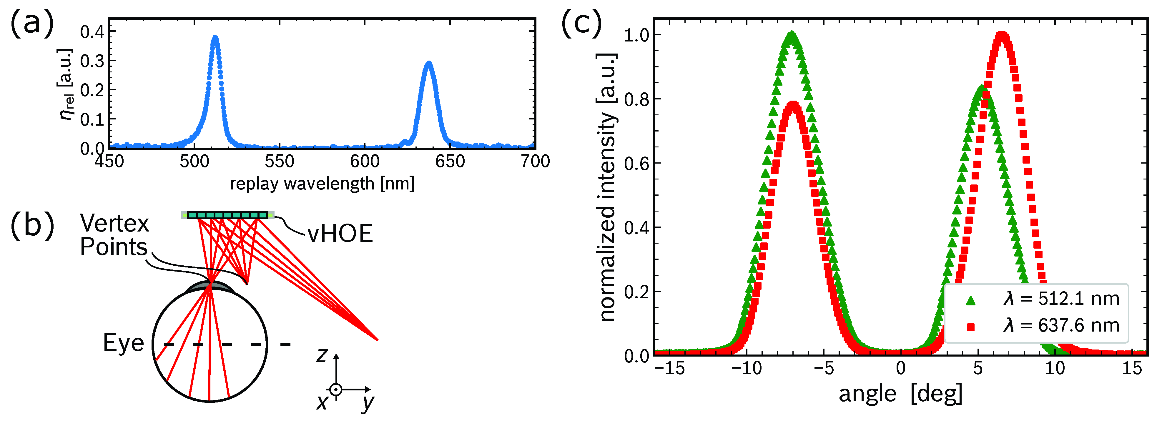
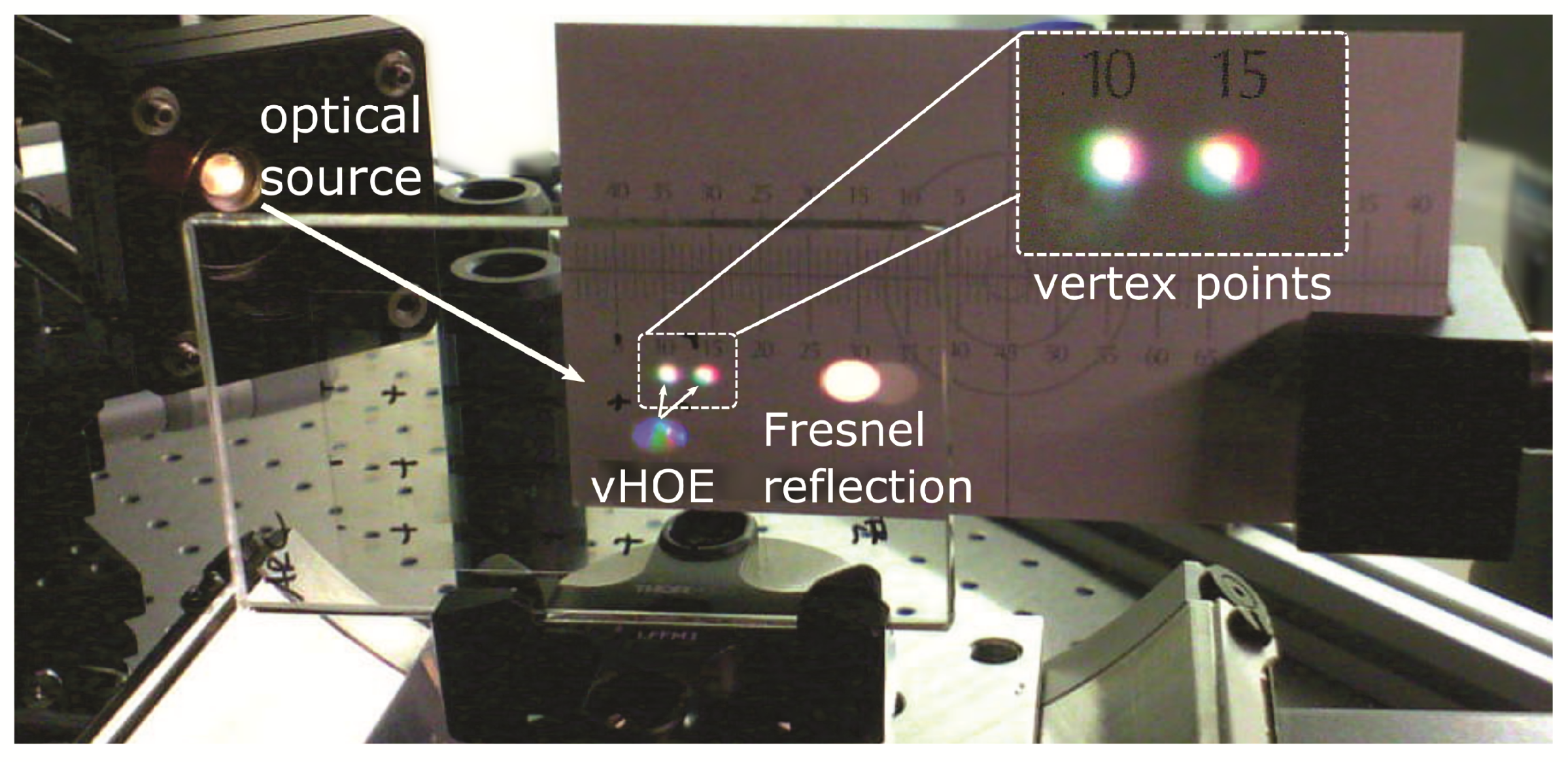
3.3. Angular Multiplexing

Extending the polychromatic vHOE from Section 3.2 by an additional angular component, the final, spectral and angular multiplexed vHOE is fabricated. A schematic representation of the vHOE’s global optical function with two vertex points is outlined in Figure 10b. The parameters obtained from Section 3.2 are employed as a basis to recorded a polychromatic vHOE, which transforms a single diverging point-source wave into two converging point-waves, resulting in two vertex points that can be employed to project an extended eye-box pattern in the red and green spectral range into the user’s field of vision. Subsequentially, each of the vHOE’s Hogels is fabricated using four sequential recording steps, realizing two angular multiplexed vertex points for the red spectral range in the first two recording pulses and the two vertex points for the green spectral range during the latter two recording pulses. A suitable energy distribution for each recording sequence is derived by adjusting the parameters from Table 2 and applying the multi-dimensional linear interpolator scheme introduced in Section 3.2 resulting in the final recording parameters of P red , 1 = 8.9   μ W c m 2 , P red , 2 = 5.6   μ W c m 2 , P green , 1 = 4.3   μ W c m 2 , P green , 2 = 11.2   μ W c m 2 , t red , 1 = t red , 2 = 265 ms and t green , 1 = t green , 2 = 390 ms.
Figure 10a outlines the vHOE’s relative diffraction efficiency η rel ( λ ) in a transmission-based evaluation at a fixed incidence angle ϑ = 45 , thus demonstrating the combined relative diffraction efficiency of both angular holographic functions to be close to the solely spectral multiplexed vHOE outlined in Figure 9a. In detail, relative diffraction efficiencies of η rel , green = 43.4 % and η rel , red = 32.9 % are achieved. In a second evaluation, the intensity distribution between the two individual, angular multiplexed vertex points is evaluated in a reflection-based direct measurement of the diffracted light. While the relative angle between the optical source and the vHOE remains fixed at the reconstruction angle, a detector is moved along a horizontal, circular path in the reflective sphere of the vHOE. As a result, the chromatic intensities around both vertex points are measured and the resulting normalized chromatic intensities are outlined in Figure 10c.
The displayed intensities are normalized to the relative chromatic peak intensity of the corresponding spectral function, resulting in the normalization wavelengths of λ = 512.1   n m and λ = 637.6   n m , respectively. The mean angular distance between both peaks is Δ β = 12.91 , which is close to the intended angular distance of β = 12.24 . The individual relative diffraction efficiencies of the angular functions are derived by taking into account the combined relative diffraction efficiency of both angular functions outlined in Figure 10a as well as the ratio of the diffracted chromatic intensities from Figure 10c, resulting in the final relative diffraction efficiencies of η rel , green , 1 = 23.6 % , η rel , green , 2 = 19.8 % , η rel , red , 1 = 14.4 % and η rel , red , 2 = 18.5 % .
Further demonstration of the vHOE’s diffraction properties are outlined in Figure 11, which depicts the vHOE under illumination of a collimated white light probing source. The relative angle between the vHOE and the optical source is adjusted to match the recording configuration, thus focusing the off-axis probing beam onto a plane and projecting two vertex points comprised of red and green spectral proportions. Additionally, the collimated white light Fresnel reflection is observable next to the vHOE’s diffracted beams. A good overlap can be observed between the two spectral functions of the first vertex point, paired with a sufficient overlap of the two spectral functions of the second vertex point. In summary, the measured chromatic intensities as well as the angular position of each individual holographic function are in good agreement with the expected recording parameters and thus demonstrate the feasibility of our recording approach. Further optimization, i.e., concerning the angular components of the second vertex point can be achieved by further fine tuning the derived recording parameters.

4. Conclusions

We presented a single-layer multiplexed holographic combiner with multiple optical functions for novel display applications such as retinal scanning devices. We outlined the design and optimization process to fabricate a holographic element, combining large off-axis to on-axis wave front transformations in the red and green spectral range with an extended eye box by employing a pupil duplication scheme. The combiner is outlined as an array-based vHOE consisting of individual Hogels, which are recorded in a sequential fashion in development grade Bayfol® HX TP* photopolymer material in our extended, immersion-based wave front printer setup. Each Hogel performs an individual holographic function contributing to the global optical combiner function of the vHOE. In detail, each holographic grating comprises four multiplexed optical functions, combining two angular and two spectral functions. The presented optimization process is comprised of a monochromatic evaluation of the employed photopolymer, resulting in the achievable index modulation based on the applied N-PSM-model for an ideal, lossless grating. Based on the monochromatic evaluation, sets of multiplexed holograms are recorded using the automated fabrication scheme of our wave front printer setup. We employed a multi-dimensional linear interpolator and demonstrated precise tuning of the vHOE’s diffractive properties. Optimized recording parameters are derived to achieve maximum diffraction efficiencies while preserving evenly distributed efficiencies between individual holographic functions comprised in the multiplexed grating. With the recorded angular and spectral multiplexed vHOE, we demonstrated relative diffraction efficiencies of η rel , green , 1 = 23.6 % , η rel , green , 2 = 19.8 % , η rel , red , 1 = 14.4 % and η rel , red , 2 = 18.5 % for each individual holographic function.
In summary, we presented a suitable approach to optimize multiple recording parameters and record a vHOE-based combiner realizing complex, multiplexed holographic functions, which demonstrates the extensive prototyping capabilities of our recording setup. We outlined a good conformity with the N-PSM model as well as the employed multi-dimensional linear interpolator, confirming the consistency and precise alignment of our optical recording setup. Minor deviations from an ideal reconstruction configuration can most likely be attributed to shrinkage effects in the photopolymer material during the multi-step recording process and can be compensated by digital adjustments to the recording parameters during future recordings. Going forward, we plan to extend the complexity of the realized holographic gratings by adding a third chromatic function in the blue spectral range, enabling full color reconstruction of the vHOE. Furthermore, we plan to enhance the presented pupil duplication scheme by adding additional eye boxes using the discrete recording scheme of our setup, which enables the recording of each Hogel with individually modulated wave fronts. Thus, the number of vertex points projected by the vHOE can be extended, without increasing the complexity of the individual holographic grating.

Author Contributions

Conceptualization, T.W. and R.F.; methodology, T.W., R.F. and J.K.; software, T.W. and J.K.; validation, T.W. and J.K.; formal analysis, T.W.; investigation, T.W.; writing—original draft preparation, T.W.; writing—review and editing, T.W., R.F. and W.S.; visualization, T.W.; supervision, R.F. and W.S. All authors have read and agreed to the published version of the manuscript.

Funding

This research received no external funding.

Data Availability Statement

Data is contained within the article.

Conflicts of Interest

The authors declare no conflict of interest.

References

  1. Tezer, M.; Yildiz, E.P.; Masalimova, A.R.R.; Fatkhutdinova, A.M.; Zheltukhina, M.R.R.; Khairullina, E.R. Trends of Augmented Reality Applications and Research throughout the World: Meta-Analysis of Theses, Articles and Papers between 2001-2019 Years. Int. J. Emerg. Technol. Learn. IJET 2019, 14, 154–174. [Google Scholar] [CrossRef]
  2. Rabbi, I.; Ullah, S. A Survey on Augmented Reality Challenges and Tracking. Acta Graph. 2013, 24, 29–46. [Google Scholar]
  3. Carmigniani, J.; Furht, B.; Anisetti, M.; Ceravolo, P.; Damiani, E.; Ivkovic, M. Augmented reality technologies, systems and applications. Multimed. Tools Appl. 2011, 51, 341–377. [Google Scholar] [CrossRef]
  4. Brooker, G. Modern Classical Optics; Oxford Master Series in Physics; Oxford University Press: Oxford, UK, 2003. [Google Scholar]
  5. Kim, S.B.; Park, J.H. Optical see-through Maxwellian near-to-eye display with an enlarged eyebox. Opt. Lett. 2018, 43, 767–770. [Google Scholar] [CrossRef]
  6. Lin, T.; Zhan, T.; Zou, J.; Fan, F.; Wu, S.T. Maxwellian near-eye display with an expanded eyebox. Opt. Express 2020, 28, 38616–38625. [Google Scholar] [CrossRef]
  7. Jang, C.; Bang, K.; Li, G.; Lee, B. Holographic Near-Eye Display with Expanded Eye-Box. ACM Trans. Graph. 2018, 37, 1–14. [Google Scholar] [CrossRef] [Green Version]
  8. Hedili, M.K.; Soner, B.; Ulusoy, E.; Urey, H. Light-efficient augmented reality display with steerable eyebox. Opt. Express 2019, 27, 12572–12581. [Google Scholar] [CrossRef] [Green Version]
  9. Park, J.H.; Kim, S.B. Optical see-through holographic near-eye-display with eyebox steering and depth of field control. Opt. Express 2018, 26, 27076–27088. [Google Scholar] [CrossRef]
  10. Kim, J.; Jeong, Y.; Stengel, M.; Akşit, K.; Albert, R.; Boudaoud, B.; Greer, T.; Kim, J.; Lopes, W.; Majercik, Z.; et al. Foveated AR: Dynamically-Foveated Augmented Reality Display. ACM Trans. Graph. 2019, 38, 1–15. [Google Scholar] [CrossRef]
  11. Kim, N.; Piao, Y.L.; Wu, H.Y. Holographic optical elements and application. In Holographic Materials and Optical Systems; IntechOpen: Rijeka, Croatia, 2017; Chapter 5; pp. 3–25. [Google Scholar]
  12. Sabel, T.; Lensen, M.C. Volume holography: Novel materials, methods and applications. In Holographic Materials and Optical Systems; IntechOpen: Rijeka, Croatia, 2017; Chapter 1; pp. 3–25. [Google Scholar]
  13. Martin, S.; Akbari, H.; Keshri, S.; Bade, D.; Naydenova, I.; Murphy, K.; Toal, V. Holographically recorded low spatial frequency volume Bragg gratings and holographic optical elements. In Holographic Materials and Optical Systems; IntechOpen: Rijeka, Croatia, 2017; Chapter 4; pp. 73–98. [Google Scholar]
  14. Hofmann, J.; Fiess, R.; Kick, M.; Stork, W. Extended holographic wave front printer setup employing two spatial light modulators. Proc. SPIE 2019, 11030. [Google Scholar] [CrossRef]
  15. Jang, C.; Mercier, O.; Bang, K.; Li, G.; Zhao, Y.; Lanman, D. Design and Fabrication of Freeform Holographic Optical Elements. ACM Trans. Graph. 2020, 39. [Google Scholar] [CrossRef]
  16. Yatagai, T.; Camacho-Basilio, J.G.; Onda, H. Recording of computer generated holograms on an optical disk master. Appl. Opt. 1989, 28, 1042. [Google Scholar] [CrossRef] [PubMed]
  17. Cable, A. Production of computer-generated holograms on recordable compact disk media using a compact disk writer. Opt. Eng. 2003, 42, 2514. [Google Scholar] [CrossRef]
  18. Sakamoto, Y.; Morishima, M.; Usui, A. Computer-generated holograms on a CD-R disk. Proc. SPIE 2004, 5290, 42–49. [Google Scholar] [CrossRef]
  19. Matsushima, K.; Kobayashi, S.; Miyauchi, H. A high-resolution fringe printer for studying synthetic holograms. Proc. SPIE 2006, 6136, 347–354. [Google Scholar] [CrossRef] [Green Version]
  20. Kang, H.; Stoykova, E.; Kim, Y.; Hong, S.; Park, J.; Hong, J. Color wavefront printer with mosaic delivery of primary colors. Opt. Commun. 2015, 350, 47–55. [Google Scholar] [CrossRef]
  21. Miyamoto, O.; Yamaguchi, T.; Yoshikawa, H. The volume hologram printer to record the wavefront of a 3D object. Proc. SPIE 2012, 8281, 153–162. [Google Scholar] [CrossRef]
  22. Nishii, W.; Matsushima, K. A wavefront printer using phase-only spatial light modulator for producing computer-generated volume holograms. Proc. SPIE 2014, 9006, 323–330. [Google Scholar] [CrossRef]
  23. Ramsbottom, A.P.; Sergeant, S.A.; Sheel, D.W. Holography for automotive head-up displays. Proc. SPIE 1992, 1667, 146–164. [Google Scholar] [CrossRef]
  24. Ando, T.; Yamasaki, K.; Okamoto, M.; Matsumoto, T.; Shimizu, E. Retinal projection display using holographic optical element. Proc. SPIE 2000, 3956, 211–216. [Google Scholar] [CrossRef]
  25. Takahashi, H.; Hirooka, S. Stereoscopic see-through retinal projection head-mounted display. Proc. SPIE 2008, 6803, 559–566. [Google Scholar] [CrossRef]
  26. Kick, M. Assembly of a Holographic Wave Front Printer for Realization of Novel Optical Systems. Ph.D. Thesis, Karlsruhe Institute of Technology (KIT), Karlsruhe, Germany, 2018. [Google Scholar]
  27. Hofmann, J.; Fiess, R.; Stork, W. Holographic wave front printing for fabrication of reflection holograms with arbitrary recording wave fronts. Proc. SPIE 2020, 11306, 1–7. [Google Scholar] [CrossRef]
  28. Wilm, T.; Höckh, S.; Fiess, R.; Stork, W. Holographic combiners for augmented reality applications fabricated by wave front recording. Proc. SPIE 2021, 11815, 13–22. [Google Scholar] [CrossRef]
  29. Noll, R.J. Zernike polynomials and atmospheric turbulence. J. Opt. Soc. Am. 1976, 66, 207–211. [Google Scholar] [CrossRef]
  30. Bruder, F.; Fäcke, T.; Rölle, T. The Chemistry and Physics of Bayfol® HX Film Holographic Photopolymer. Polymers 2017, 9, 472. [Google Scholar] [CrossRef] [PubMed] [Green Version]
  31. Brotherton-Ratcliffe, D. Understanding Diffraction in Volume Gratings and Holograms. In Holography; IntechOpen: Rijeka, Croatia, 2013; Chapter 1. [Google Scholar] [CrossRef] [Green Version]
  32. Kogelnik, H. Coupled Wave Theory for Thick Hologram Gratings. Bell Syst. Tech. J. 1969, 48, 2909–2947. [Google Scholar] [CrossRef]
  33. Brotherton-Ratcliffe, D. Analytical treatment of the polychromatic spatially multiplexed volume holographic grating. Appl. Opt. 2012, 51, 7188–7199. [Google Scholar] [CrossRef] [PubMed]
  34. Vázquez-Martín, I.; Marín-Sáez, J.; Gómez-Climente, M.; Chemisana, D.; Collados, M.V.; Atencia, J. Full-color multiplexed reflection hologram of diffusing objects recorded by using simultaneous exposure with different times in photopolymer Bayfol® HX. Opt. Laser Technol. 2021, 143, 107303. [Google Scholar] [CrossRef]
Figure 1. (a) Digitally designed phase patterns to define the hologram’s global optical function, including two one-dimensional graphs, outlining the horizontal cross-section of both phase patterns. Segments of the global phase patterns are relayed onto two SLMs, to shape the recording wave fronts. (b) Illustration of the vHOE fabrication process by sequential recording of individual Hogels. Microscope images of the recorded vHOE via (c) phase-contrast-, (d) dark-field- and (e) bright-field-microscopy.
Photonics 09 00419 g001
Figure 2. Schematic representation of the employed holographic wave front printer setup. Two laser-based optical sources are collimated (C), aligned on a common optical axis and tuned by an AOTF before being evenly split up and relayed onto two SLMs (SLM1, SLM2), which shape the wave fronts according to the recording configuration. The resulting wave fronts are traversing two symmetrical optical systems, each containing multiple achromatic relay lenses (R, L), a spatial filter (F) and an immersion-based microscope objective (IMO). Both recording wave fronts interfere in a plane of holographic film, positioned by a high-precision two-dimensional translation stage (XY).
Photonics 09 00419 g002
Figure 3. Theoretical diffractive characteristics of polychromatic holograms based on the N-PSM model according to Equation (4). The graphs outline recording scenarios assuming different fractions of the maximum index modulation n max being consumed of polychromatic holograms with holographic functions in the red and green spectral regime.
Photonics 09 00419 g003
Figure 4. Normalized transmission spectrum of the employed optical source, a bleached photopolymer film and a recorded vHOE. The relative diffraction efficiency η rel of the vHOE is determined from the vHOE’s chromatic selectivity, normalized to the bleached photopolymer film transmission spectrum.
Photonics 09 00419 g004
Figure 5. Relative diffraction efficiencies obtained for holograms recorded in the green (a) and red (b) spectral function.
Photonics 09 00419 g005
Figure 6. Derived index modulation values according to Equation (5) for holograms recorded in the green (a) and red (b) spectral function.
Photonics 09 00419 g006
Figure 7. (a) Measured relative diffraction efficiencies of several holograms recorded at equal exposure energies; however, at different exposure times. A time dependence of the achievable diffraction efficiency can be observed. The inset outlines several power sweeps outlining, the saturation regime of the holograms at the evaluated energy level (red bar). (b) Outline of the vHOE’s bandwidth as FWHM for equal energy levels as displayed in (a).
Photonics 09 00419 g007
Figure 8. Schematic representation of the recording process for a single Hogel, governed by the two virtual point sources P 1 and P 2 . The Hogel’s volume holographic grating is described by the grating vector K ̲ , which is governed by the recording wave fronts characteristics described by k 1 ̲ and k 2 ̲ .
Photonics 09 00419 g008
Figure 9. (a) Chromatic relative diffraction efficiency of the vHOE measured at a fixed incidence angle of ϑ = 45 . (b) Schematic of the vHOE’s global optical function with a single vertex point. (c) Two-dimensional contour graph, which outlines the vHOE’s relative diffraction efficiency η rel ( ϑ , λ ) as a function of the horizontal incidence angle ϑ and the probing wavelength λ . Two fit functions are applied to the outlined dataset using Bragg’s equation (Equation (6)).
Photonics 09 00419 g009
Figure 10. (a) Relative diffraction efficiency η rel ( λ ) of the multiplexed vHOE for a fixed incidence angle at ϑ = 45 . (b) Schematic of the vHOE’s global optical function with two vertex points. (c) Normalized chromatic intensity of the multiplexed vHOE measured at various angles of diffraction in the same half-sphere as the optical source. During the measurement, the optical source is positioned with a fixed incidence angle to the vHOE corresponding to the recording configuration.
Photonics 09 00419 g010
Figure 11. Collimated white light illumination of the vHOE under an incident angle matching the recording configuration. Two vertex points with red and green spectral proportions, diffracted by the vHOE as well as the Fresnel reflection of the collimated white light beam can be observed in the image.
Photonics 09 00419 g011
Table 1. Fit parameters, monochromatic evaluation.
λ = 515 nm λ = 639 nm
t [ms] n max [a.u.] E 0
[µJcm 2 ]
γ [a.u.] n max [a.u.] E 0
[µJcm 2 ]
γ [a.u.]
400.00960.8350.30.00880.7652.7
1200.01010.7571.10.09861.39171.5
2000.01131.04143.80.01251.08138.0
4000.01381.6911560.01541.69364.9
Table 2. Results of the multi-dimensional linear interpolator.
λ = 515 nm λ = 639 nm
P rec [ μ W c m 2 ]14.013.1
t rec [ms]389.5263.2
η M dim , interp [%]39.341.6
η N PSM [%]37.538.6
η rel , meas [%]3941
Table 3. Fit parameters of Bragg’s equation.
λ = 515 nm λ = 639 nm
| K ̲ rec | [ / m ]2.36 × 1071.90 × 107
| K ̲ fit | [ / m ]2.37 × 1071.89 × 107
Λ rec [ n m ]265.9330.4
Λ fit [ n m ]264.9331.0
ϑ K , rec [deg]14.614.6
ϑ K , fit [deg]12.912.6
Publisher’s Note: MDPI stays neutral with regard to jurisdictional claims in published maps and institutional affiliations.

