Single-Mode Input Fiber Combined with Multimode Sensing Fiber Used in Brillouin Optical Time-Domain Reflectometry

 ,
,
Abstract
:1. Introduction
2. Theory
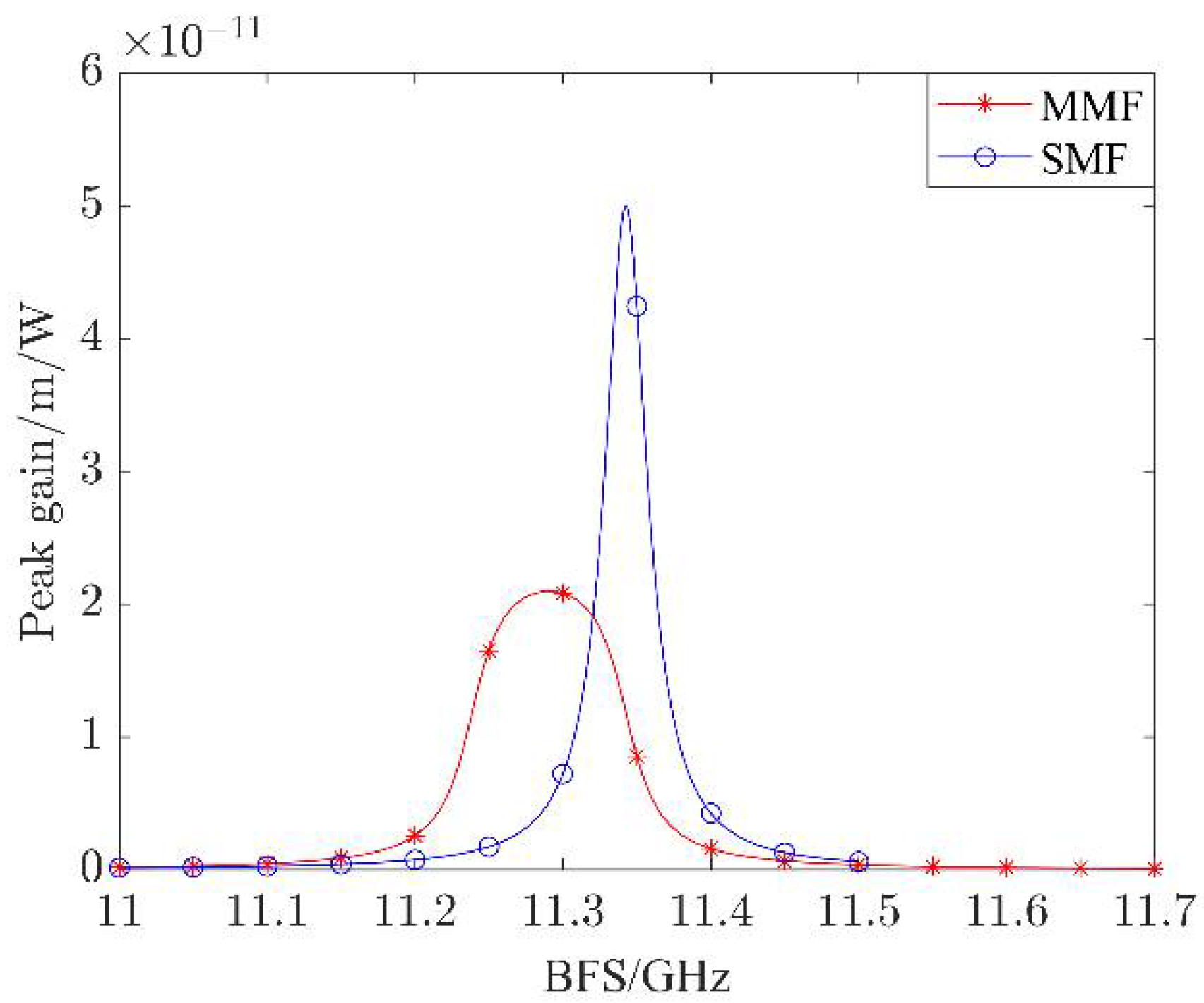
2.1. BGS of MMF
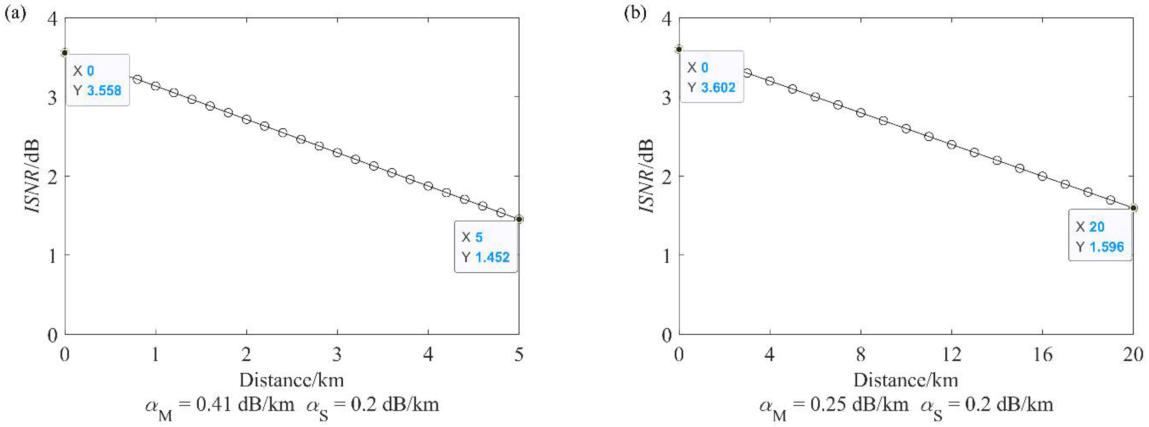
2.2. Improvement of SNR
2.3. Fundamental Mode Excitation and High-Order Modes Filtering in GI-MMF
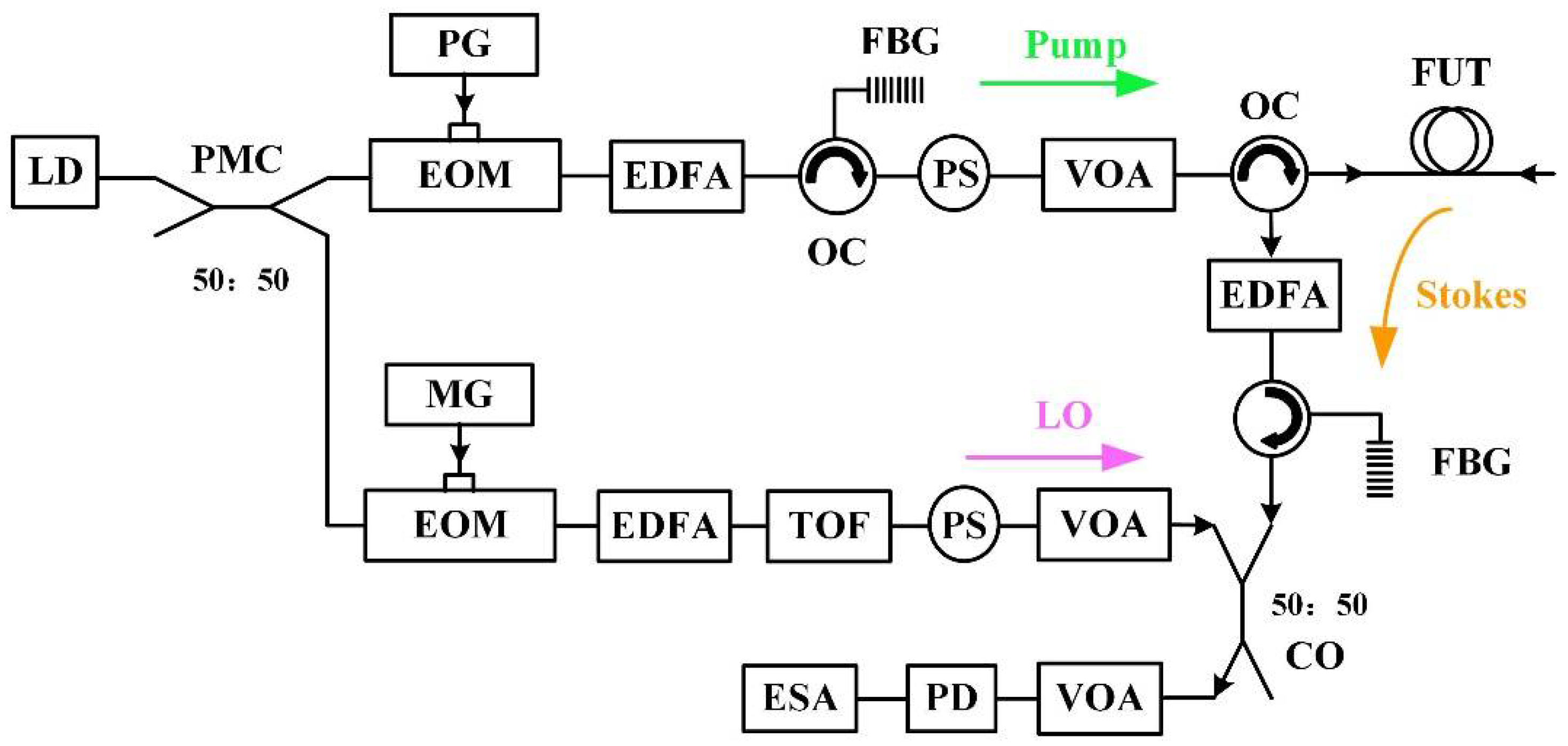
3. Experiment and Discussion
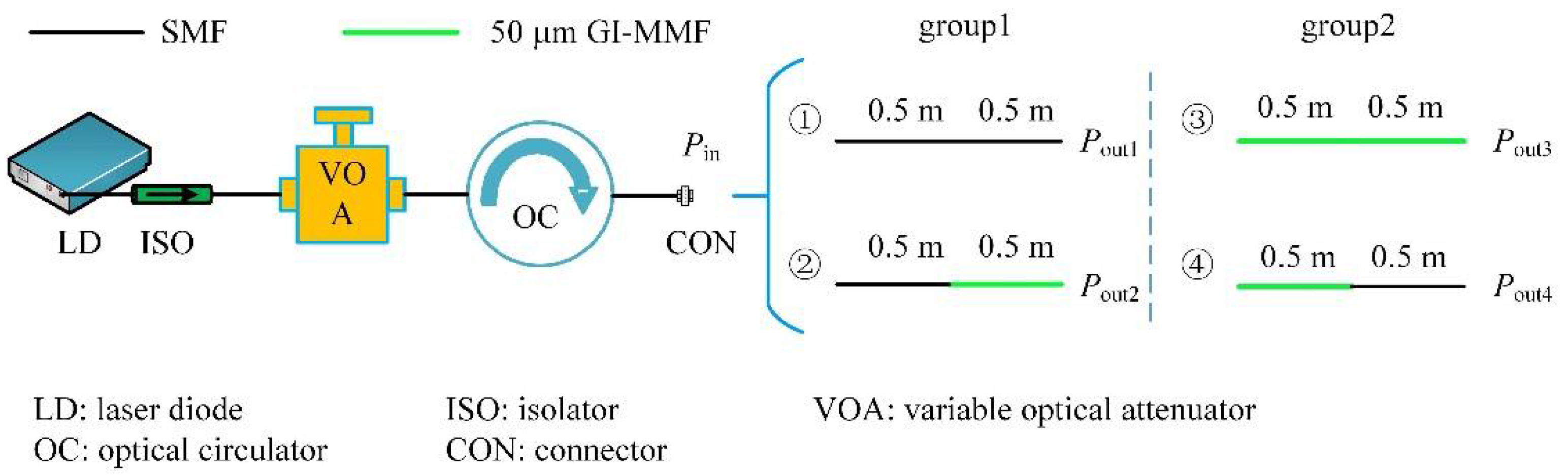
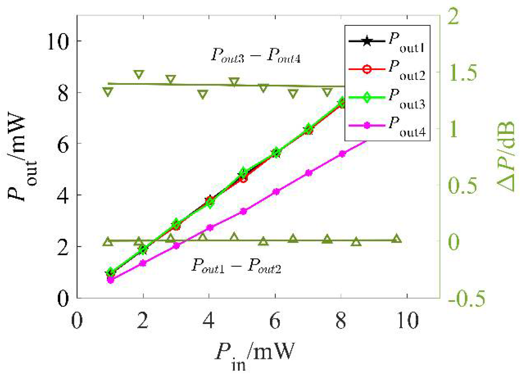
3.1. Measurement of Coupling Characteristics of SMF Alignment Fusion to 50 μm GI-MMF
3.2. Experimental Verification of ISNR
3.3. Fresnel Reflection Elimination and Bending Characteristic Measurements
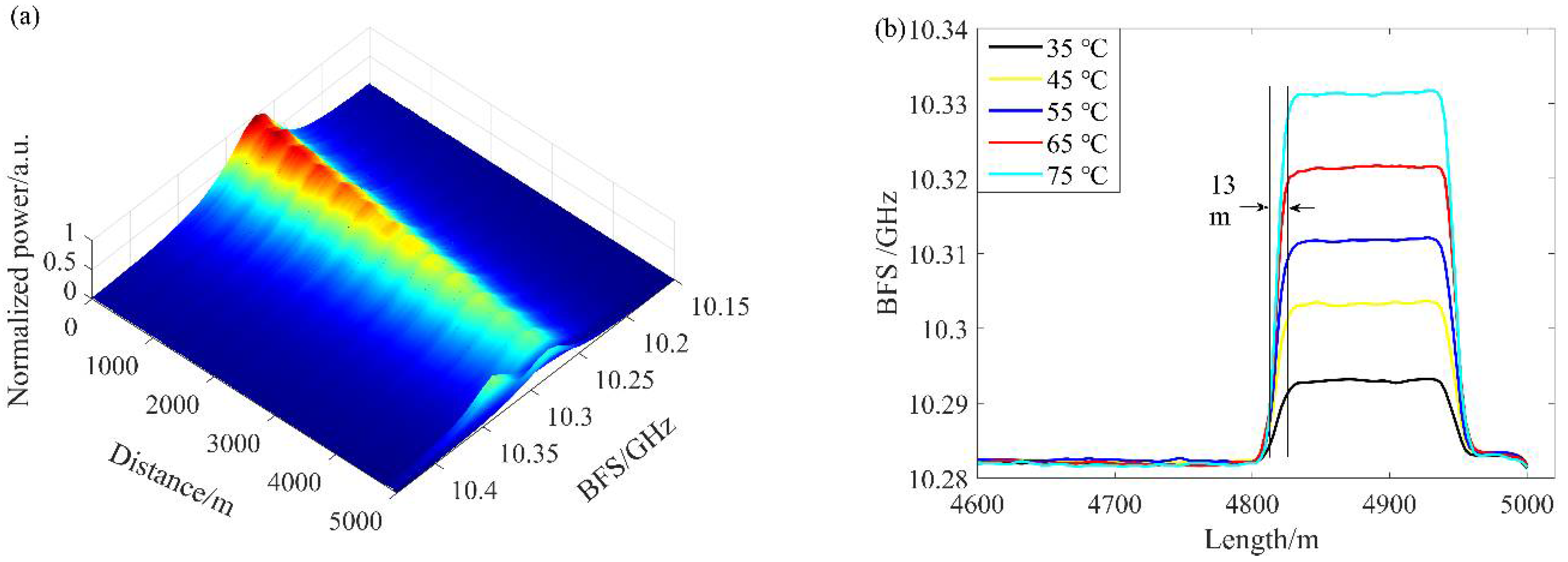
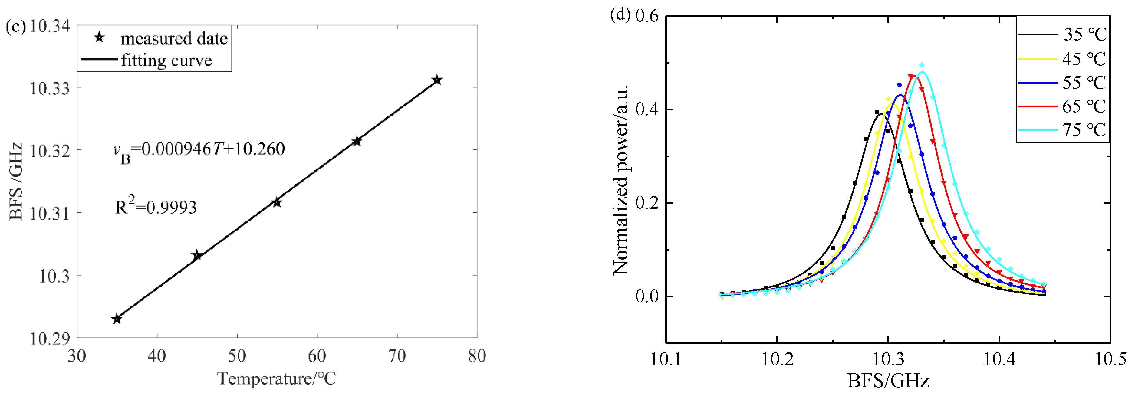
3.4. Temperature-Sensing Characteristics
4. Conclusions
Author Contributions
Funding
Institutional Review Board Statement
Informed Consent Statement
Data Availability Statement
Conflicts of Interest
References
- Hu, D.J.J.; Humbert, G.; Dong, H.; Zhang, H.; Hao, J.; Sun, Q. Review of specialty fiber based Brillouin optical time domain analysis technology. Photonics 2021, 8, 421. [Google Scholar] [CrossRef]
- Hu, T.; Hou, G.; Li, Z. The field monitoring experiment of the roof strata movement in coal mining based on DFOS. Sensors 2020, 20, 1318. [Google Scholar] [CrossRef] [PubMed] [Green Version]
- Gu, K.; Shi, B.; Liu, C.; Jiang, H.; Li, T.; Wu, J. Investigation of land subsidence with the combination of distributed fiber optic sensing techniques and microstructure analysis of soils. Eng. Geol. 2018, 240, 34–47. [Google Scholar] [CrossRef]
- Feng, T.; Zhou, J.; Shang, Y.; Chen, X.; Yao, X. Distributed transverse-force sensing along a single-mode fiber using polarization-analyzing OFDR. Opi. Express 2020, 28, 31253–31271. [Google Scholar] [CrossRef]
- Zhang, X. Distributed Optical Fiber Sensing Techniques; Science Press: Beijing, China, 2013; pp. 1–25. [Google Scholar]
- Liu, T.; Liu, K.; Dai, L.; Jiang, J.; Wang, J.; Ding, Z.; Sang, M.; Hu, H.; Wang, S.; Xue, C.; et al. Research progress of key technologies in recognition sensing for opto-electronic information and event. Acta Optica Sin. 2021, 41, 0106002. [Google Scholar] [CrossRef]
- Dong, Y. High-performance distributed Brillouin optical fiber sensing. Photonic Sens. 2021, 11, 69–90. [Google Scholar] [CrossRef]
- Bi, W.; Yang, X.; Li, J.; Fu, X.; Fu, G. Forward and backward Raman amplification of Brillouin scattering signal in Brillouin optical time domain reflectometer system. Chin. J. Lasers 2014, 41, 1205007. [Google Scholar] [CrossRef]
- Mizuno, Y.; Theodosiou, A.; Kalli, K.; Liehr, S.; Lee, H.; Nakamura, K. Distributed polymer optical fiber sensors: A review and outlook. Photonics Res. 2021, 9, 1719–1733. [Google Scholar] [CrossRef]
- Maughan, S.M.; Kee, H.H.; Newson, T.P. Simultaneous distributed fibre temperature and strain sensor using microwave coherent detection of spontaneous Brillouin backscatter. Meas. Sci. Technol. 2001, 12, 834–842. [Google Scholar] [CrossRef]
- Shimizu, K.; Horiguchi, T.; Koyamada, Y.; Kurashima, T. Coherent self-heterodyne detection of spontaneously Brillouin-scattered light waves in a single-mode fiber. Opt. Lett. 1993, 18, 185–187. [Google Scholar] [CrossRef]
- Minakawa, K.; Mizuno, Y.; Nakamura, K. Cross effect of strain and temperature on Brillouin frequency shift in polymer optical fibers. J. Lightwave Technol. 2017, 35, 2481–2486. [Google Scholar] [CrossRef]
- Lee, C.C.; Chiang, P.W.; Chi, S. Utilization of a dispersion-shifted fiber for simultaneous measurement of distributed strain and temperature through Brillouin frequency shift. IEEE Photonics Technol. Lett. 2001, 13, 1094–1096. [Google Scholar] [CrossRef] [Green Version]
- Li, A.; Wang, Y.; Fang, J.; Li, M.; Kim, B.Y.; Shieh, W. Few-mode fiber multi-parameter sensor with distributed temperature and strain discrimination. Opt. Lett. 2015, 40, 1488–1491. [Google Scholar] [CrossRef] [PubMed]
- Song, K.Y.; Kim, Y.H. Characterization of stimulated Brillouin scattering in a few-mode fiber. Opt. Lett. 2013, 38, 4841–4844. [Google Scholar] [CrossRef]
- Zou, W.; He, Z.; Kishi, M.; Hotate, K. Stimulated Brillouin scattering and its dependences on strain and temperature in a high-delta optical fiber with F-doped depressed inner cladding. Opt. Lett. 2007, 32, 600–602. [Google Scholar] [CrossRef]
- Zou, L.; Bao, X.; Afshar, V.S.; Chen, L. Dependence of the Brillouin frequency shift on strain and temperature in a photonic crystal fiber. Opt. Lett. 2004, 29, 1485–1487. [Google Scholar] [CrossRef] [Green Version]
- Tommya, B.; Guillaumea, B.; Steevea, M.; Younsa, M.; Richardb, F.; Françoisc, T.; Martinaet, B. Curvature sensing using a hybrid polycarbonate-silica multicore fiber. Opt. Express 2020, 28, 39387–39399. [Google Scholar] [CrossRef]
- Mohamed, A.S.Z.; Wang, M.; Giovanni, M.; Li, M.; Li, S.; Huang, Y.; Wang, T.; Chen, K.P. Discrimination of temperature and strain in Brillouin optical time domain analysis using a multicore optical fiber. Sensors 2018, 18, 1176. [Google Scholar] [CrossRef] [Green Version]
- Kuyt, G. Fast progress in ITU for bend-loss insensitive singlemode fiber. Lightwave 2007, 24, 19. [Google Scholar]
- Zhang, Z.; Lu, Y.; Pan, Y.; Bao, X.; Chen, L. Trench-assisted multimode fiber used in Brillouin optical time domain sensors. Opt. Express 2019, 27, 11396–11405. [Google Scholar] [CrossRef]
- Ren, G.; Lin, Z.; Zheng, S.; Jian, S. Resonant coupling in trenched bend-insensitive optical fiber. Opt. Lett. 2013, 38, 781–783. [Google Scholar] [CrossRef] [PubMed]
- Watekar, P.R.; Ju, S.; Yoon, Y.S.; Lee, Y.S.; Han, W.T. Design of a trenched bend insensitive single mode optical fiber using spot size definitions. Opt. Express 2008, 16, 13545–13551. [Google Scholar] [CrossRef] [PubMed]
- Nakajima, K.; Hogari, K.; Jian, Z.; Tajima, K.; Sankawa, L. Hole-assisted fiber design for small bending and splice losses. IEEE Photonics Technol. Lett. 2003, 15, 1737–1739. [Google Scholar] [CrossRef]
- Saitoh, K.; Tsuchida, Y.; Koshiba, M. Bending-insensitive single-mode hole-assisted fibers with reduced splice loss. Opt. Lett. 2005, 30, 1779–1781. [Google Scholar] [CrossRef]
- Tsuchida, Y.; Saitoh, K.; Koshiba, M. Design and characterization of single-mode holey fibers with low bending losses. Opt. Express 2005, 13, 4770–4779. [Google Scholar] [CrossRef] [Green Version]
- Wang, Z.; Zhao, C.; Jin, S. Design of a bending-insensitive single-mode photonic crystal fiber. Opt. Fiber Technol. 2013, 19, 213–218. [Google Scholar] [CrossRef]
- Behera, B.L.; Maity, A.; Varshney, S.K.; Datta, R. Theoretical investigations of trench-assisted large mode-area, low bend loss and single-mode microstructured core fibers. Opt. Commun. 2013, 307, 9–16. [Google Scholar] [CrossRef]
- Martelli, C.; Canning, J.; Gibson, B.; Huntington, S. Bend loss in structured optical fibres. Opt. Express 2007, 15, 17639–17644. [Google Scholar] [CrossRef]
- Zailani, N.F.H.; Saidin, N.; Rusdi, M.F.M.; Harun, S.W.; Thirunavakkarasu, P.M. Acetone liquid sensing based on fiber optic Mach-Zehnder interferometer. In Proceedings of the 2021 IEEE Regional Symposium on Micro and Nanoelectronics (RSM), Kuala Lumpur, Malaysia, 2–4 August 2021. [Google Scholar] [CrossRef]
- Akbarpour, Z.; Ahmadi, V.; Roghabadi, F.A. Refractive index sensor based on wavelength shift analysis in MSM optical fiber structure. In Proceedings of the 28th Iranian Conference on Electrical Engineering (ICEE), Tabriz, Iran, 4–6 August 2020. [Google Scholar] [CrossRef]
- Li, Y.; Fan, H.; Zhang, L.; Wang, K.; Wu, G.; Liu, Z. A bend-resistant BOTDR distributed fiber sensor. Opt. Commun. 2022, 514, 128110. [Google Scholar] [CrossRef]
- Sodhi, S.S.; Jackman, W.S. Strain measurement in multimode fibers using Brillouin optical time-domain reflectometry. In Proceedings of the Optical Fiber Communication Conference, San Jose, CA, USA, 22–27 February 1998. [Google Scholar] [CrossRef]
- Minardo, A.; Bernini, R.; Zeni, L. Analysis of the Brillouin gain spectrum in a graded-index multimode fiber. In Proceedings of the Third Mediterranean Photonics Conference, Trani, Italy, 7–9 May 2014. [Google Scholar] [CrossRef]
- Mocofanescu, A.; Wang, L.; Jain, R.; Shaw, K.D.; Gavrielides, A.; Peterson, P.; Sharma, M.P. SBS threshold for single mode and multimode GRIN fibers in an all fiber configuration. Opt. Express 2005, 13, 2019–2024. [Google Scholar] [CrossRef]
- Iezzi, V.L.; Loranger, S.; Harhira, A.; Rehman, S. Stimulated Brillouin scattering in multi-mode fiber for sensing applications. In Proceedings of the 7th International Workshop on Fiber and Optical Passive Components, Montreal, QC, Canada, 13–15 July 2011. [Google Scholar] [CrossRef]
- Li, Y.; Zhao, X.; Zhao, L.; Ma, L.; Li, X.; An, Q. Brillouin scattering parameters of different modes in multimode optical fibers. Acta Photonica Sin. 2015, 44, 27–33. [Google Scholar] [CrossRef]
- Bayvel, P.; Radmore, P.M. Solutions of the SBS equations in single mode optical fibers and implications for fiber transmission systems. Electron. Lett. 1990, 26, 434–436. [Google Scholar] [CrossRef]
- Li, C.; Lu, Y.; Zhang, X.; Wang, F. SNR enhancement in Brillouin optical time domain reflectometry using multi-wavelength coherent detection. Electron. Lett. 2012, 48, 1–3. [Google Scholar] [CrossRef]
- Horiguchi, T.; Tateda, M. BOTDA-nondestructive measurement of single-mode optical fiber attenuation characteristics using Brillouin interaction: Theory. J. Lightwave Technol. 1989, 7, 1170–1176. [Google Scholar] [CrossRef]
- Gu, W.; Huang, Y.; Chen, X.; Zhang, J.; Zhang, M.; Yu, S. Optical Fiber Communication; Posts & Telecommunications Press: Beijing, China, 2011; pp. 1–26. [Google Scholar]
- Minardo, A.; Bernini, R.; Zeni, L. Experimental and numerical study on stimulated Brillouin scattering in a graded-index multimode fiber. Opt. Express 2014, 22, 17480–17489. [Google Scholar] [CrossRef]
- Donlagić, D.; Brianb, C. Propagation of the fundamental mode in curved graded index multimode fiber and its application in sensor systems. J. Lightwave Technol. 2000, 18, 334–342. [Google Scholar] [CrossRef]
- Cui, Q.; Pamukcu, S.; Lin, A.; Xiao, W.; Toulouse, J. Performance of double sideband modulated probe wave in BOTDA distributed fiber sensor. Microwave Opt. Technol. Lett. 2010, 52, 2713–2717. [Google Scholar] [CrossRef]


| Parameter (Units) | g0 (m/W) | g1 (m/W) | B | TB (ns) |
|---|---|---|---|---|
| Value | 5 × 10⁻¹¹ | 2.096 × 10⁻¹¹ | 21 | 10 |
| Parameter (Units) | VA (m/s) | k (J/K) | T (K) | λ (nm) |
| Value | 5940 | 1.38 × 10⁻²³ | 300 | 1550 |
| Parameter (Units) | vB (GHz) | AeffS (m2) | neffS | p12 |
| Value | 11 | 9.5 × 10⁻¹¹ | 1.45 | 0.27 |
| Parameter (Units) | ρ (kg/m3) | AeffM (m2) | neffM | W (ns) |
| Value | 2200 | 1.9677 × 10⁻¹⁰ | 1.48 | 130 |
Publisher’s Note: MDPI stays neutral with regard to jurisdictional claims in published maps and institutional affiliations. |
© 2022 by the authors. Licensee MDPI, Basel, Switzerland. This article is an open access article distributed under the terms and conditions of the Creative Commons Attribution (CC BY) license (https://creativecommons.org/licenses/by/4.0/).
Share and Cite
Li, Y.; Fan, H.; Zhang, L.; Liu, Z.; Wang, L.; Wu, J.; Wang, S. Single-Mode Input Fiber Combined with Multimode Sensing Fiber Used in Brillouin Optical Time-Domain Reflectometry. Photonics 2022, 9, 398. https://doi.org/10.3390/photonics9060398
Li Y, Fan H, Zhang L, Liu Z, Wang L, Wu J, Wang S. Single-Mode Input Fiber Combined with Multimode Sensing Fiber Used in Brillouin Optical Time-Domain Reflectometry. Photonics. 2022; 9(6):398. https://doi.org/10.3390/photonics9060398
Chicago/Turabian StyleLi, Yongqian, Haijun Fan, Lixin Zhang, Zijuan Liu, Lei Wang, Jiaqi Wu, and Shaokang Wang. 2022. "Single-Mode Input Fiber Combined with Multimode Sensing Fiber Used in Brillouin Optical Time-Domain Reflectometry" Photonics 9, no. 6: 398. https://doi.org/10.3390/photonics9060398