1. Introduction
Photonic-crystal microresonators (MCRs) have recently attracted the close attention of researchers both in terms of their fundamental properties and in connection with the wide possibilities of their practical application. One-dimensional MCRs represent a structure in which dielectric Bragg reflectors are used as mirrors [
1,
2,
3,
4,
5,
6,
7]. Microresonators are used to create a wide class of radiation control devices (switches, modulators, filters) of various ranges, performing the function of amplifying various types of light interaction with a propagation medium. Thus, in the optical range, in order to increase the rate of spontaneous emission of single quantum emitters, resonators based on optical fibers are widely considered, in which the working cavity is enclosed between Bragg gratings [
8,
9,
10,
11,
12,
13]. A symmetric photonic crystal MCR is formed from two identical dielectric Bragg mirrors (BMs) separated from each other by a certain distance along their axis, and it is necessary to change the order of the layers in one of the BMs. The area between the mirrors (cavity) is usually filled with an active medium. Due to the multiple reflection of radiation between the mirrors, standing waves (resonator modes) are formed. In plane-parallel resonators, only those modes are supported for which the distance between the mirrors is a multiple of half the propagating radiation wavelength. In this case, transmission resonances are observed in photonic band gaps (PBGs). Their number, position, and amplitude are determined by the width of the cavity and the reflection coefficient of the mirrors. For many practical applications, it is important to be able to tune the resonant frequency of the MCR by changing the external parameters. Efficient rearrangement of the transmission and reflection spectra of the MCR can be achieved by introducing into the cavity between the mirrors a medium whose material parameters depend on easily changed external factors [
11,
12,
13,
14,
15,
16,
17].
In this work, we study the features of the transmission spectrum of a structure MCR whose working cavity is filled with a magnetically active finely layered structure with material parameters controlled by an external magnetic field. For this kind of structure materials, we chose doped semiconductor and ferrospinel . This choice (semiconductor and magnet) is due to the fact that the frequencies of the magnetic and cyclotron resonances are close and fall into the first band gap of the BMs. In this case, both orthogonally polarized eigenwaves (TE and TM) become controlled by an external magnetic field. The use of this fine-layered structure makes it possible to effectively control the radiation passing through the microresonator (and, consequently, reflected). The paper presents the frequency and field dependences of the structure eigenwaves transmission coefficient at different thicknesses of the effective medium filling the working cavity. The polarization characteristics of radiation passing through a MCR and the possibility of polarization control using an external magnetic field are studied.
2. Basic Relationships
Let us consider a symmetrical MCR formed by two Bragg mirrors (BMs) and a cavity separating them. The period of the BMs consists of two layers of isotropic dielectrics with permittivity
and
and equal optical thicknesses
. The cavity, the length of which
and the permittivity
, will be filled with a magnetically active flat-layered structure, composed of semiconductor and ferrite layers with thicknesses
and
(see
Figure 1). The material parameters (permittivity and permeability of each of the layers) in the studied high-frequency range are scalar-tensor quantities, i.e., for a semiconductor, this is
and
, for a ferrite,
and
. In the absence of an external magnetic field, such one-dimensional structure has the properties of the uniaxial crystal with symmetry axis perpendicular to the interfaces between the layers (
axis). A plane linearly polarized wave is introduced into the structure along this axis and propagates in it.
The action of the magnetic field leads to the anisotropy of the optical properties of the semiconductor and ferrite. For the field
oriented in the layer plane along the
axis, the tensor parameters have the form:
In this geometry, the corresponding components of the semiconductor permittivity tensor
,
,
depend on the frequency and external magnetic field as follows [
18]:
where the plasma and cyclotron frequencies of the semiconductor are introduced
and
,
is the lattice part of the permittivity,
e is the electron charge,
and
are the concentration and effective mass of carriers,
,
is the relaxation parameter. For ferrite, the components of the tensor magnetic permeability
,
and
have the form [
19,
20]:
where
,
is saturation magnetization,
,
is the width of the magnetic resonance line, and
is the magnetomechanical relationship. In this case, the permeability of the semiconductor is taken equal to unity (
), and the permittivity of ferrite is
(spinel
).
Furthermore, we assume that the thickness of the semiconductor and ferrite layers is small compared to the length of the waves propagating in the structure and its period is
. Therefore, it is possible to use the long-wave approximation and introduce the effective material parameters of the fine-layer "ferrite-semiconductor" medium. The eigenwaves of the effective medium are TE and TM waves with wave field components
and
and propagation constants:
Here, the following notations are introduced [
21,
22]:
where parameter is
.
Figure 2a,b shows the frequency dependences of the real part of the effective permittivity
of the semiconductor (a) and the effective permeability
of the ferrite (b). The semiconductor parameters were used for the calculations
:
,
,
,
and spinel
parameters:
,
,
, as well as field values
(curves 1–4). It can be seen that an increase in the external magnetic field shifts the resonant curve toward higher frequencies. At the same time, the characteristics of the TM wave in the semiconductor layers, and the TE wave in the ferrite layers are sensitive to the magnetic field. Thus, the material parameters of the effective medium can be controlled by a magnetic field.
For the MCR structure with an effective medium filling the resonator cavity, the transfer matrix connecting the wave field at the input and output of the structure has the form
, where
a is the number of periods in the BM. The transfer matrices of individual layers have the form:
where
for TE-wave and
for TM-wave,
are the propagation constants in the layers of the BM, the propagation constants for the effective medium
and
are determined by the relations (
4),
,
and
c are the frequency and the wave speed in the vacuum. If the resonator cavity remains empty, then
.
The amplitude reflection and transmission coefficients for the entire MCR structure are determined through the matrix elements of the transfer matrix [
23]:
The energy reflection and transmission coefficients in this case have the form , . When absorption in layers is taken into account, the fraction of energy absorbed by the structure is determined by the quantity .
To reveal the spectral features of the MCR that arise when the cavity is filled with an effective bigyrotropic medium, let us first consider the distribution of the wave field over a structure with an unfilled cavity. We assume that the period of the BM consists of two layers of isotropic dielectrics and with permittivity and and equal optical thicknesses . Here, , where the operating frequency is chosen equal to s. In this case, the real thicknesses of the layers are m and m. In each of the mirrors, the number of periods is , and the period of the structure is m, the thickness of each mirror is cm.
Figure 3a,b shows the distribution over the MCR structure of the normalized electric field
squared modulus for different cavity sizes. The operating frequency, for which the distribution of the electric field amplitude is constructed, corresponds to the frequency of the central mode
. The thin line shows the distribution of the permittivity along the longitudinal coordinate of the MCR. It can be seen that, for the structure with
(a) at its center, the electric field amplitude reaches the minimum, and two maxima occur at the side boundaries of the cavity. In this case, the amplitude of the magnetic field in the center of the cavity reaches the maximum, and at its boundaries with BMs, it reaches the minimum. The incident wave weakly penetrates into the structure, since at the chosen operating frequency the cavity plays the role of a reflecting quarter-wave plate; this follows at
(b) from the field distribution.
3. Transmission Spectra of the Microcavity
Let us consider the transformation of the MCR transmission spectrum when its cavity is filled with an effective medium.
Figure 4 shows the frequency dependences of the transmittance
T for the case of an unfilled cavity (left) and a filled one (right). The spectra were obtained at
for the cavity size
(
). It can be seen that the width and number of narrow peaks in the PBG change with increasing
. For the first three values of the unfilled cavity thickness at the band gap center, there is a narrow transmission peak (defective mode). In the case of a quarter-wavelength thickness (d), this peak is absent. Note that the effective medium is isotropic in the layer plane (
) when there is no external magnetic field, so the realized spectrum does not depend on the polarization of the eigenwave propagating in the structure.
When the cavity is filled with a bigyrotropic effective medium, its optical thickness is not constant but depends on both the frequency and the magnitude of the external field. In this case, the phase-matching conditions become field-dependent; therefore, the nature of the spectrum also depends on the external field and changes significantly in comparison with the spectra in the absence of the field and, moreover, in the absence of the cavity filling.
Figure 5 show the transmission spectra of TE (a,c) and TM (b,d) waves of the MCR filled with an effective medium for two cavity sizes
(a,b) and
(c,d), at magnetic field values
(curves 1–4). It can be seen that, as the field increases, the character of the frequency dependence of the transmission coefficient changes significantly and depends both on the thickness of the effective medium and on the type of the incident wave.
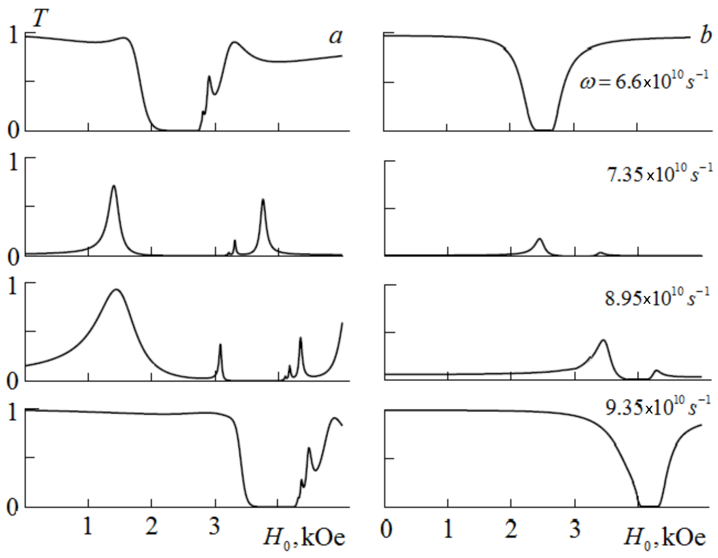
Figure 6 shows the external field dependences of the TE and TM waves (a,b) transmission coefficient at several frequencies and size
for an MCR with the cavity filled with an effective medium. It can be seen that for some frequencies there are fields’ intervals where the transmission of waves of both polarizations is almost complete, and there are intervals where the wave transmission is complete only for one polarization. The presence of such intervals in the spectrum makes it possible to use a structure similar to a MCR as a filter or polarizer controlled by a magnetic field.
4. Polarization Characteristics
To determine the polarization characteristics of a MCR with an effective medium, we assume that the polarization plane of the wave incident on the structure makes angle
with the
axis (i.e., with the vector
). The electric field of the wave transmitted through a MCR can be represented as the sum of the fields of eigenwaves
. At the exit from the MCR, the components of the electric field are determined by the expressions
To describe the transmitted wave polarization state, we introduce the complex polarization variable [
24]:
where
is the angle of inclination of the ellipse major axis to the axis
, and
is the phase mismatch of eigenwaves when passing through the MCR. The angle
and ellipticity
parameters are determined by the expressions:
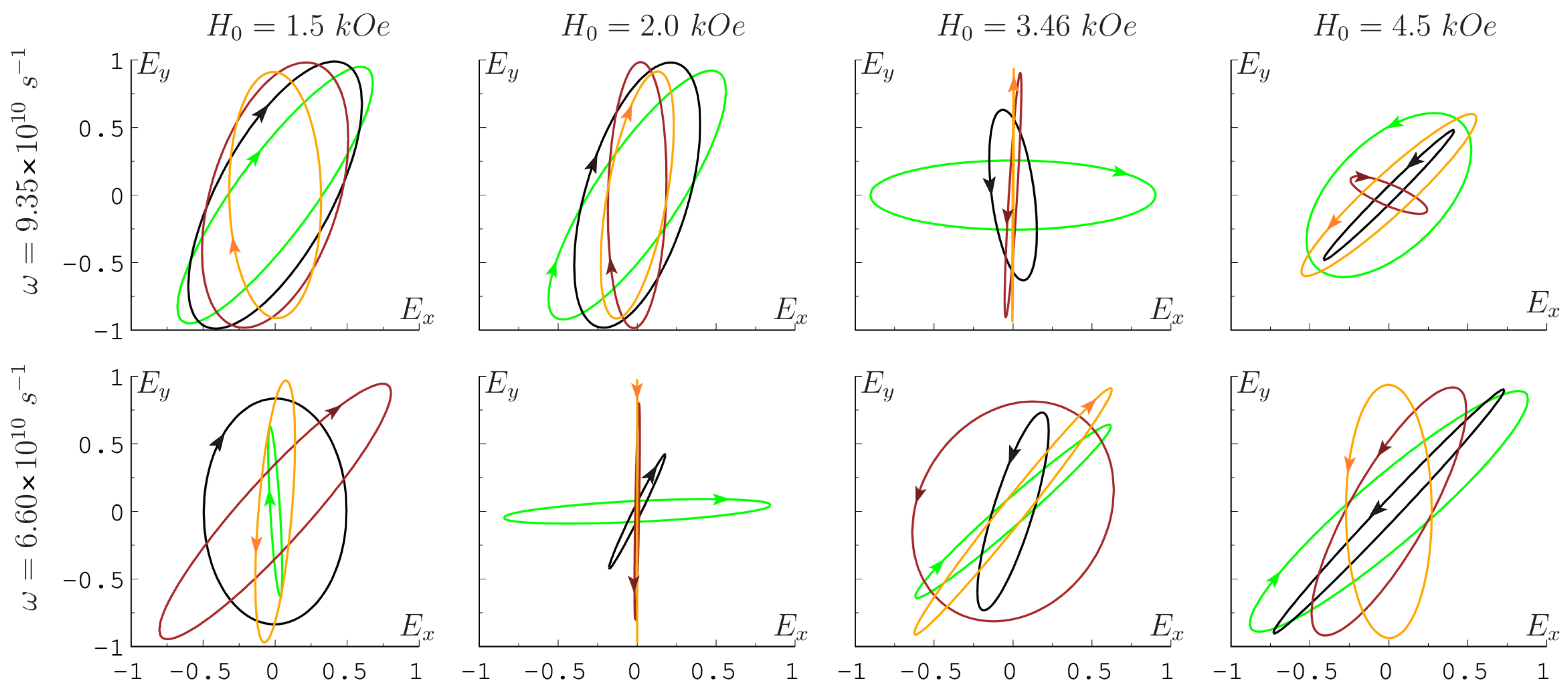
Figure 7 shows the polarization ellipses of the wave transmitted through the structure, obtained with the orientation of the plane of the wave incident polarization on the structure
, at two frequencies and four values of the parameter
(green, black, brown, and yellow lines, the arrows indicate the direction of vector
motion). It can be seen from the shape of the polarization ellipses that both the magnitude of the ellipticity and the angle of inclination of the major axis depend significantly on the frequency, on the applied magnetic field, and on the ratio of the layer thicknesses in the structure period. Therefore, these parameters of the wave passing through the MCR are easily controlled within a fairly wide range.
5. Discussion
In the present work, when modeling the transmission spectra of a Bragg MCR, we used the parameters of an impurity semiconductor and a ferrospinel . Specific materials of the layered structure were chosen so that the frequencies of the magnetic and cyclotron resonances were close and fell into the PBG of the BMs. In this case, the change in the magnetic field leads to a significant change in the character of the transmission spectrum for waves of both polarizations. Note that, by choosing the materials of ferrite and semiconductor, it is possible to spread the indicated frequencies into different ranges (for example, and ). At the same time, only the TE wave spectrum can be magnetically sensitive at a low operating frequency, and only the TM wave spectrum can be magnetically sensitive at a high operating frequency. By choosing the materials of the effective medium layers and changing the BM period, the operating range of the MCR can also be transferred to the infrared or optical region. To do this, it is necessary to create an effective medium for the resonator cavity based on two semiconductors (for example, and -type with a sufficiently high carrier concentration). In this case, only the TM wave with the control regions separated in frequency will be controlled by the magnetic field.
A distinctive feature of photonic crystals including MCR structures for the microwave range is high manufacturability, macroscopicity, and the possibility of their implementation on the basis of ordered arrays of various shapes’ elements. The presence of pronounced band gaps and narrow allowed minibands (defect modes) makes it possible to use microwave photonic crystals of the considered geometry as controllable narrow-band transmission filters and polarization elements. We also note that the advantage of one-dimensional photonic crystal structures in comparison with two-dimensional and three-dimensional ones is the simplicity and low cost of their fabrication. At the same time, despite their good knowledge, one-dimensional structures continue to be the objects of research to obtain new or modify existing materials with new optical properties.


