1. Introduction
An optoelectronic oscillator (OEO) is a feedback loop oscillator consisting of electrical and optical parts [
1,
2,
3]. The long length (approximately several tens of kilometers) of an optical fiber with a low loss (~0.2 dB/km) in the OEO configuration provides a large time delay in the feedback loop, which helps in achieving the low-phase noise in the OEO signal [
4,
5]. In other words, the time delay of the feedback loop is inversely proportional to the phase noise of the OEO signal. Furthermore, the high-frequency performance of the OEO outperforms that of the other high-frequency oscillators, because the OEO phase noise is not degraded with an increase in the oscillation frequency [
2]. Moreover, the OEO can be applied to numerous applications, such as optical communications, computing, and sensing, owing to its superior signal quality and optoelectronic configuration [
6,
7]. Various OEO configurations have been proposed to achieve ultra-low phase noise performance [
8,
9,
10], simple modulation processes [
11], and a threshold gain reduction [
12].
Although the OEO performance has been improved in various prior studies, the reduction in the spurious tones of the OEO signal remains a critical issue and causes hindrance to the real-field applications of the OEO [
13]. Spurious tones occur because of the interference between the feedback signals in the OEO loop [
3]. They occur at approximately hundreds of kilohertz intervals when an optical fiber of several kilometers in length is used in the OEO loop. For example, when a 1 km length of the OEO is implemented, the corresponding interval of the spurious tones is 200 kHz [
3]. The spurious tones cannot be easily filtered out by the electrical bandpass filter (BPF) because they are narrowly spaced, owing to the long-length optical fiber loop. In addition, they degrade the long-term stability of the OEO signal power owing to the mode competition between the OEO signal and the spurious tones. To overcome these issues, a multi-loop OEO (MOEO) and injection-locked OEO were proposed and found to be effective [
14,
15]. However, compared to a single-loop OEO, they require additional components, such as an optical fiber, optical combiner/splitter, and photodetector. The additional components might result in a large form factor and high cost [
16].
To overcome these challenges, we propose a spurious tone reduction using a low-frequency modulated single-loop OEO. The laser in the single-loop OEO is directly modulated by a low radio frequency (RF) signal. The frequency of the RF signal is adjusted based on a spurious tone interval. The directly modulated laser in the OEO loop exhibits optical sidebands. The gain competition between the sidebands and spurious tones suppresses the oscillation of the spurious tones, resulting in a reduction in the spurious tones and an improvement in the long-term stability of the oscillation signal.
In this study, we demonstrate a simple OEO configuration with low-level spurious tones based on an RF-modulated DM-OEO. The target OEO frequency is 15 GHz, with a 1 km fiber loop, and the spurious tone interval was 200 kHz. Therefore, the laser was directly modulated with a low-frequency RF signal to achieve the gain competition between the modulation sideband and spurious tones. We achieved a side-mode suppression ratio (SMSR) of 40.14 dB and an enhancement in the long-term stability by 2.55 dB compared with those of the single-loop OEO without a rectangular wave modulation. The simple OEO configuration with low-level spurious tones based on an RF-modulated DM-OEO can be applied to various optical, RF, and RF photonics systems, including optical/wireless communications, optical signal processing, and frequency standards.
2. Operating Principle
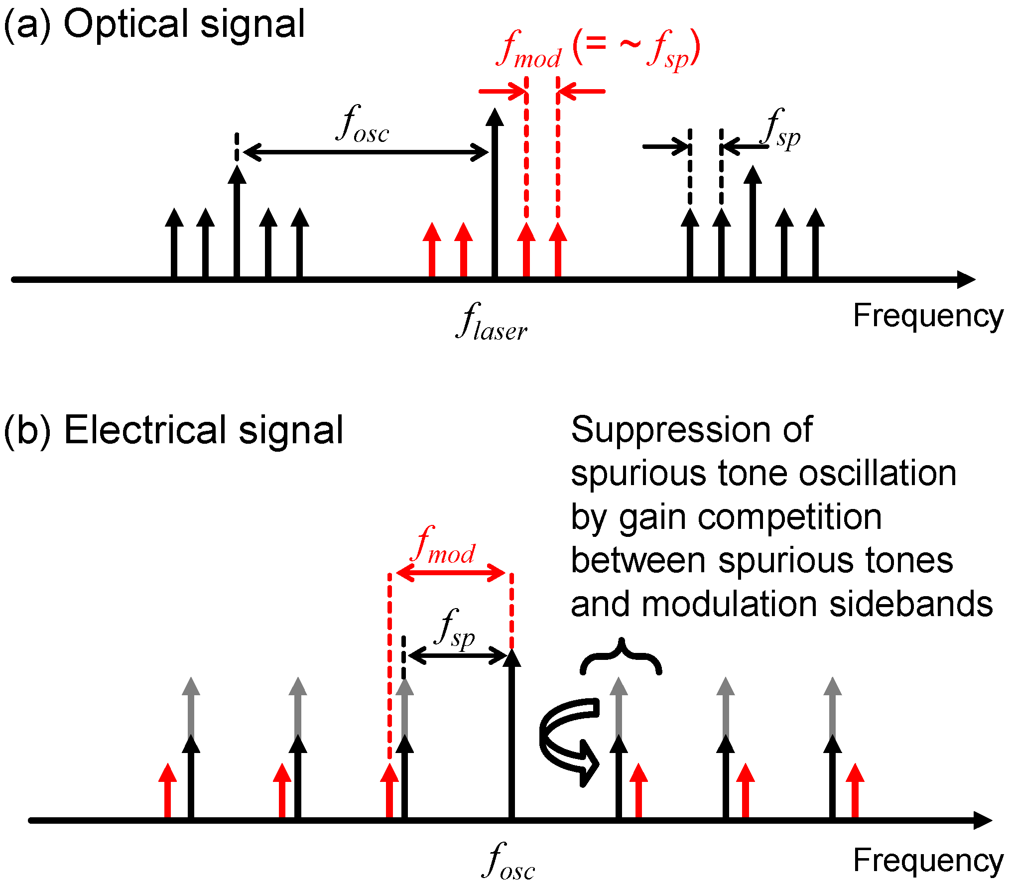
Figure 1 shows the operating principle of the spurious tone reduction in a single-loop DM-OEO signal using a low-frequency RF signal.
Figure 1a shows the optical spectrum of a single-loop RF-modulated DM-OEO. The optical spectrum can be obtained using an optical spectrum analyzer (OSA) in the DM-OEO configuration (as shown in
Figure 2 in our experimental setup). The figure shows the OEO signals located by the oscillation frequency
fosc from the center frequency of the laser,
flaser. The spurious tones due to the OEO feedback loop are located at an interval of
fsp from
flaser. The interval of
fsp is determined by the total loop length of the DM-OEO system. Because we applied RF modulation to the laser with a frequency
fmod, the spectrum also possessed the modulation sidebands located at the RF-modulated frequency
fmod from the center frequency of the laser (indicated by red arrows). The RF modulation frequency was roughly the same as
fsp.
Figure 1b shows the electrical spectrum of a single-loop RF-modulated DM-OEO. It can be obtained using an electrical spectrum analyzer (ESA) in the DM-OEO configuration, as shown in
Figure 2. The electrical spectrum could be obtained by the square-law detection of the optical signals in a photodetector. The OEO target signal is located at the frequency
fosc. The spurious tones are located at
fsp from
fosc, and the modulation sidebands are located at
fmod from
fosc. We believe that the gain competition between the spurious tones and the modulation sidebands in the laser cavity suppresses the oscillation of the spurious tones, resulting in a spurious tone reduction. The power stability of the oscillation signal was simultaneously achieved owing to the suppression of the spurious oscillation. Consequently, we could reduce the spurious tones and improve the oscillation power stability based on the RF-modulated single-loop DM-OEO.
3. Experimental Results
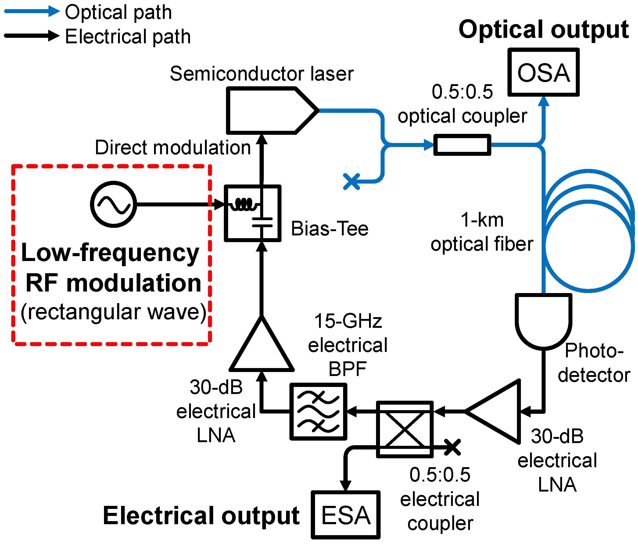
We proposed an RF-modulated single-loop DM-OEO to reduce the spurious tones, and
Figure 2 shows the experimental setup. The black and blue solid lines represent the optical and electrical signals, respectively. The optical part of a single-loop OEO consisted of a semiconductor laser at 1550 nm, optical coupler, 1 km optical fiber, and photodetector. Meanwhile, the electrical part of a single-loop OEO consisted of 30 dB low-noise amplifiers (LNAs), electrical coupler, BPF with a 15 GHz center frequency and 100 MHz bandwidth, and a bias tee. The laser was directly modulated by a feedback signal and an external RF signal of a low-frequency rectangular wave. We could apply the rectangular signal via a dc port of a bias tee, because the signal frequency was sufficiently low for the signal to pass through the port without using a broadband RF coupler. The frequency of the rectangular wave was set to a low value to achieve gain competition. To achieve the intentional gain competition between the modulation sideband and spurious tones, the modulation frequency had to be set close to the spurious tone interval but not necessarily at the same value. For the modulation signal format, a rectangular wave was preferred, owing to its ability to generate higher powers of harmonic sidebands than those generated with a sinusoidal wave. The study on the frequency and modulation format dependencies on the spurious tone reduction was reserved for future work [
17]. The threshold gain for loop oscillation was 65 dB, owing to the electrical-to-optical and optical-to-electrical conversion and coupler losses. Further, the losses were compensated by the two LNAs. The threshold current of the semiconductor laser was 8 mA, and the laser was biased at 32.72 mA. In addition to the conventional DM-OEO configuration, we applied an RF-modulated signal of a rectangular wave. The additional low-frequency modulation enabled the spurious tone reduction as well as an improvement in the oscillation power stability.
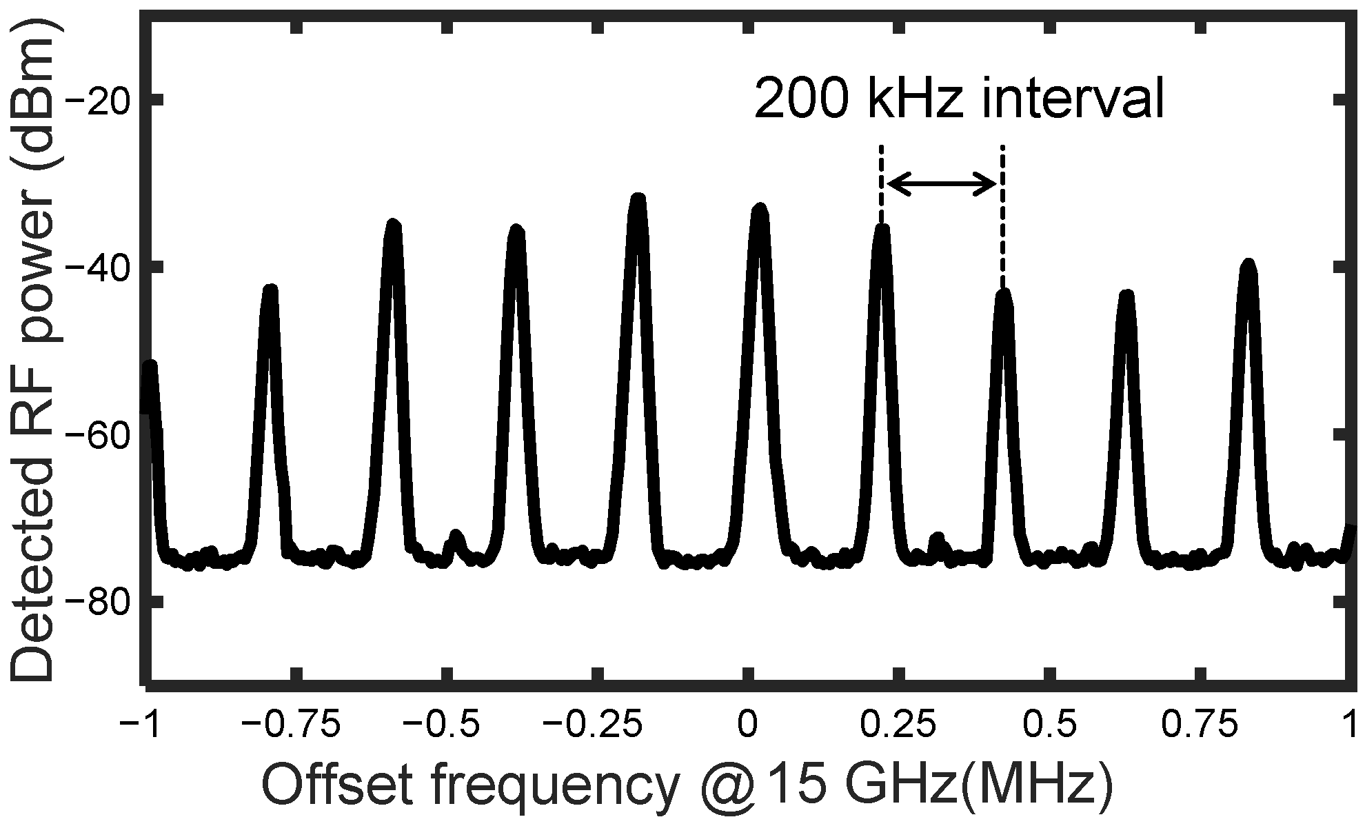
Figure 3 shows the OEO signal spectrum without the rectangular wave modulation. The frequency interval of the spurious tones was 200 kHz, which corresponded to a 1 km OEO loop. When the laser was not modulated by a rectangular wave, the spurious tones were not suppressed. There was no significant difference in the amplitude of RF power between the oscillation target and spurious modes. We modulated the laser with the RF-modulated signal of a rectangular wave with a duty cycle of 50% and an amplitude of 5 mA. The SMSR was measured as a function of the RF modulation frequencies [
18]. We defined SMSR as the difference between the oscillation target mode and the largest spurious mode. We measured the electrical spectrum as a function of modulation frequencies from 180 kHz to 255 kHz at intervals of 5 kHz. The RF spectra of the four most representative results are shown in
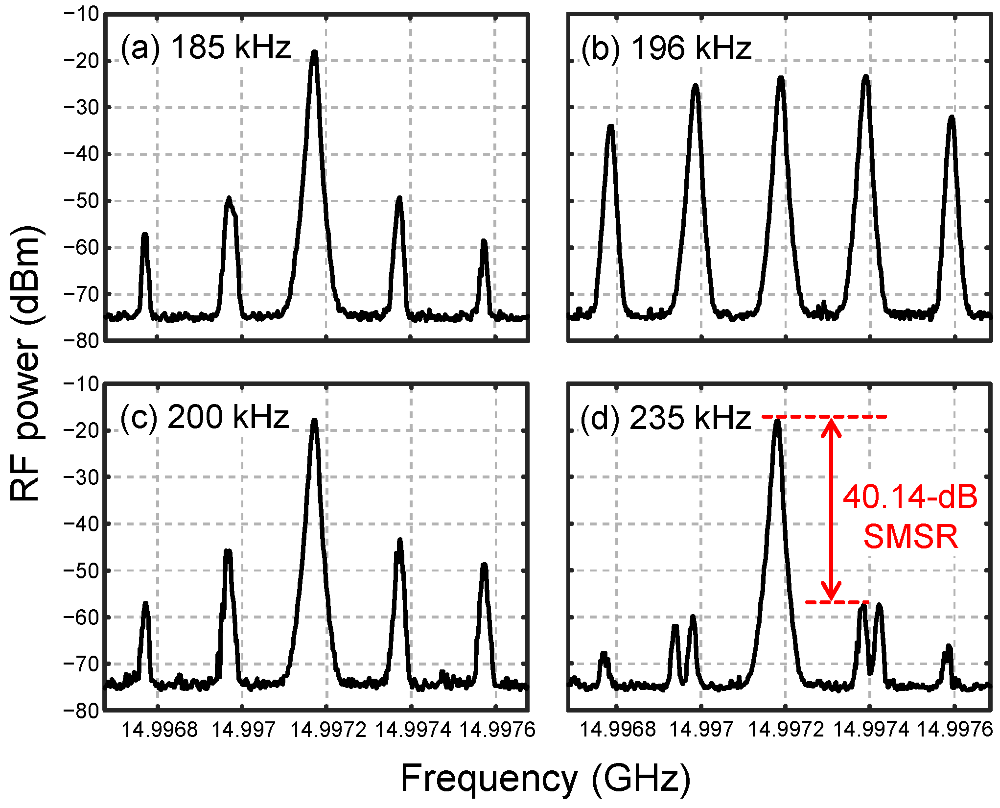
Figure 4.
Figure 4a–d shows the measured electrical spectra of the OEO by various RF modulation frequencies at 185, 196, 200, and 235 kHz, respectively. As shown in
Figure 4b,d, the lowest and highest SMSRs were exhibited at 196 kHz and 235 kHz, respectively.
Figure 4d exhibits the largest SMSR of 40.14 dB, because the gain competition between the modulated sidebands and spurious modes was maximized with the modulation frequency.
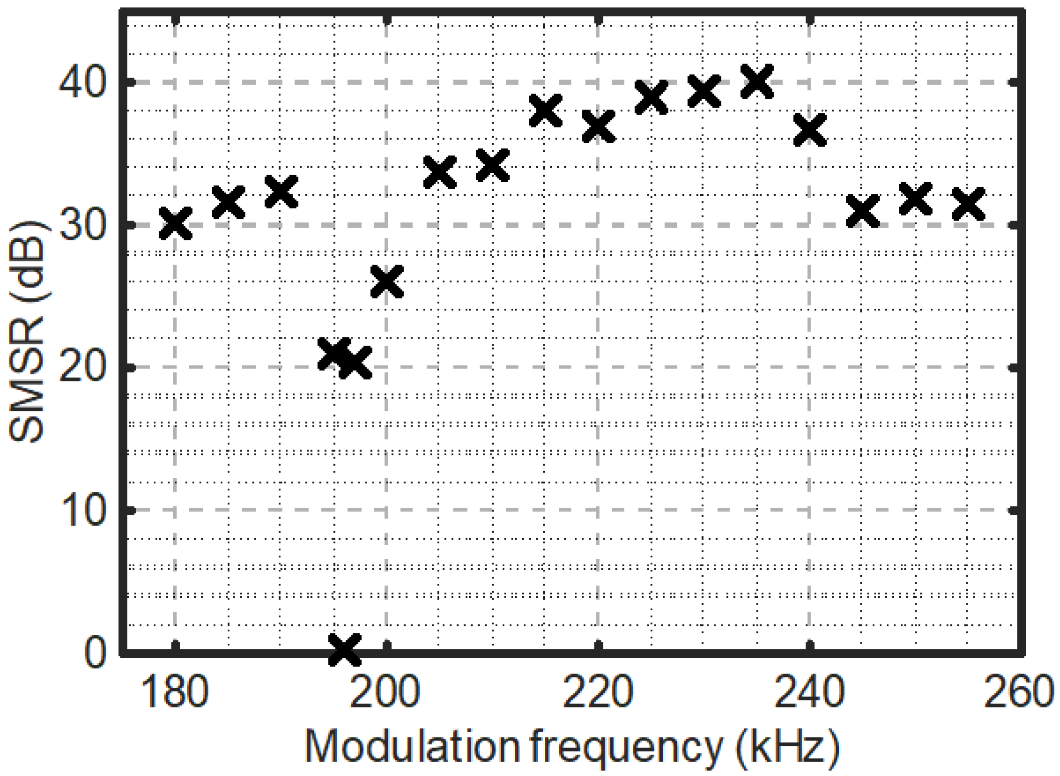
Figure 5 shows the SMSR as a function of various RF modulation frequencies from 180 kHz to 255 kHz at intervals of 5 kHz. The smallest SMSR of 1.55 dB was observed at the 196 kHz modulation frequency, because the spurious tone corresponded to the modulation frequency, which caused a strong oscillation of the spurious modes. The largest SMSR of 40.14 dB was observed at the 235 kHz modulation frequency, as shown in
Figure 4d.
Figure 6 shows the time stability of the oscillation power at 15 GHz. We applied an RF-modulated signal of a rectangular wave with a period of 4.29 μs (i.e., 233.00 kHz), duty cycle of 50%, and amplitude of 10 mA. The red and black solid lines represent the cases with and without the rectangular wave modulation, respectively. We tracked the oscillation frequency, measured the oscillation power every 1.21 s, and calculated the standard deviations of the oscillation power. It was observed that the standard deviation of the oscillation power was 0.44 dBm and 2.99 dBm with and without the rectangular wave modulation, respectively. The oscillation power stability in terms of the standard deviation of the oscillation power was improved by 2.55 dB owing to the suppression of the spurious tone oscillation. We observed that a mode hopping (dashed circles) between the oscillation target mode and spurious modes occurred when there was no modulation, while it was not observed for the case of modulation.
4. Discussion
We demonstrated a reduction in spurious modes and the improvement of the oscillation power stability based on a directly modulated laser with a low-frequency RF signal in a single-loop OEO. The gain competition between the spurious tones and optical modulation sidebands, owing to the RF signal modulation, suppressed the oscillation of the spurious modes. We achieved the suppression of the spurious modes by modulating the laser in the OEO loop with a rectangular wave of frequency close to the fiber-free spectral range. We confirmed the SMSR dependence on the modulation frequency and achieved a value of 40.14 dB at a modulation frequency of 235 kHz. Further, we achieved the long-term stability of the oscillation signal owing to the elimination of the mode hopping between the oscillation target mode and spurious modes. As a result, a 2.55 dB improvement was achieved in the oscillation power stability compared to that without an RF modulation. The proposed single-loop DM-OEO with a low-frequency RF modulation could be applied to a wide range of optoelectronic applications, such as RF photonics, frequency standards, optical communication, optical signal processing, and LiDAR, owing to its simplicity, mode stability, and cost-effectiveness.


