Article

Accelerated Generation of a Pinhole-Type Holographic Stereogram Based on Human Eye Characteristics in Near-Eye Displays

1
School of Instrumentation and Opto-Electronics Engineering, Hefei University of Technology, Hefei 230009, China
2
National Engineering Laboratory of Special Display Technology, National Key Laboratory of Advanced Display Technology, Academy of Photoelectric Technology, Hefei University of Technology, Hefei 230009, China
*
Author to whom correspondence should be addressed.
Photonics 2022, 9(2), 95; https://doi.org/10.3390/photonics9020095
Submission received: 14 January 2022 / Revised: 29 January 2022 / Accepted: 2 February 2022 / Published: 7 February 2022
(This article belongs to the Special Issue Computer Holography)

Abstract

:
In near-eye displays (NEDs), issues such as weight, heat, and power consumption mean that the rendering and computing power is usually insufficient. Due to this limitation, algorithms need to be further improved for the rapid generation of holograms. In this paper, we propose two methods based on the characteristics of the human eye in NEDs to accelerate the generation of the pinhole-type holographic stereogram (HS). In the first method, we consider the relatively fixed position of the human eye in NEDs. The number of visible pixels from each elemental image is very small due to the limited pupil size of an observing eye, and the calculated amount can be dramatically reduced. In the second method, the foveated region rendering method is adopted to further enhance the calculation speed. When the two methods are adopted at the same time, the calculation speed can be increased dozens of times. Simulations demonstrate that the proposed method can obviously enhance the generation speed of a pinhole-type HS.

1. Introduction

Near-eye displays have attracted a great deal of interest since they are essential devices giving immersive and interactive experiences in virtual reality (VR) and augmented reality (AR) applications [1,2]. Most commercial NEDs are based on binocular disparities by presenting a pair of stereoscopic images, which causes a mismatch between the accommodation distance and the convergence distance of human eyes. Holographic NEDs can effectively overcome the accommodation–convergence conflict (AC conflict) by reconstructing the wavefront of three-dimensional (3D) images [3]. Compared to other advanced 3D display technologies, such as super multi-view displays [4], integral imaging [5,6], multi-focal display [7] and tensor displays [8], holographic displays have the very crucial advantage that they can offer all depth cues that human eyes require by reproducing both light intensity and phase.
Although holographic displays have a bright future, the rapid generation of high-quality computer-generated holograms (CGHs) is a major challenge. Usually, there are two types of algorithms for calculating CGHs: wave-optics-based algorithms and ray-optics-based algorithms. Wave-optics-based algorithms mainly contain the point-source-based methods [9], polygon-based methods [10] and layer-based methods [11]. However, in these methods, complicated physical phenomena, such as occlusion, shading, reflection, refraction, glossiness, and transparency, are hard to encode into the CGH [12]. These features are essential for photorealistic reconstruction. Although there are still some methods based on point sources or polygons to achieve gloss surface reconstruction, it is difficult to achieve real-time display [13,14].
The ray-optics-based algorithm records the light ray information of parallax images, which are also called element images (EIs), captured from 3D objects, and these features can be solved with the help of the multiple view-point rendering technique. Many researchers have reported on encoding the parallax images to a hologram, resulting in methods such as the diffraction calculation method [15], the orthographic projection image method [16], the fast Fourier transform (FFT) method [17], the ray sampling method [18,19], the resolution priority method [20], and so on.
The pinhole-type HS method [21,22] is also a fast calculation method to record the light field information captured by a pinhole-type integral imaging (PII) system [23,24] into a hologram. The method works by recording the diffraction patterns produced by the pinholes, and reconstructing multi-depth images. In some cases, the calculation speed of the pinhole-type HS is even faster than the FFT method [17]. During the reconstruction process, the observer’s eye can sample light rays from the virtual pinholes. This means that the spatial resolution of the reconstructed object is determined by the number of pinholes or EIs. In order to improve the display quality, it is usually possible to increase the number of pinholes while keeping each EI’s resolution unchanged, but this will bring additional rendering costs and computational costs [22]. However, in the NED, considering issues such as weight, heat and power consumption, the computing power is usually insufficient. Therefore, the generation speed of pinhole-type HSs needs to be further improved.
In this paper, we propose two methods based on the characteristics of the human eye in NEDs to accelerate the generation of the pinhole-type HS. In the first method, we consider the relatively fixed position of the human eye in NEDs [25]. Since the pupil size of a human eye is small, only part of the wavefront emitted from each pinhole can be observed. This part of the wavefront usually corresponds to only a few pixels of each EI. Therefore, the generation speed can be accelerated, since the number of pixels needed to be rendered and calculated is greatly reduced. In the second method, the foveated region rendering method is adopted to further enhance the calculation speed [26,27,28,29]. The human eye has high resolution only in the foveated region, and low resolution in the peripheral region. The foveated rendering technique usually reduces the resolution in the peripheral area, shorting the generation time without degrading the perceived image quality. In this paper, the pinhole plane is divided into a foveated region and several peripheral areas. The number of pinholes in peripheral areas is appropriately decreased, which means the number of corresponding EIs needed to be calculated is significantly reduced, and the calculation speed is naturally improved. Simply, the first method can be adopted to reduce the number of pixels of each EI, and the second method is used to decrease the number of EIs. In fact, these two methods can be used in parallel: the total improvement is the product of the two methods. For the sake of simplicity, this paper only compares the improvements of the computing speed. Simulations demonstrate that the proposed methods can obviously enhance the generation speed of pinhole-type HSs.

2. Materials and Methods

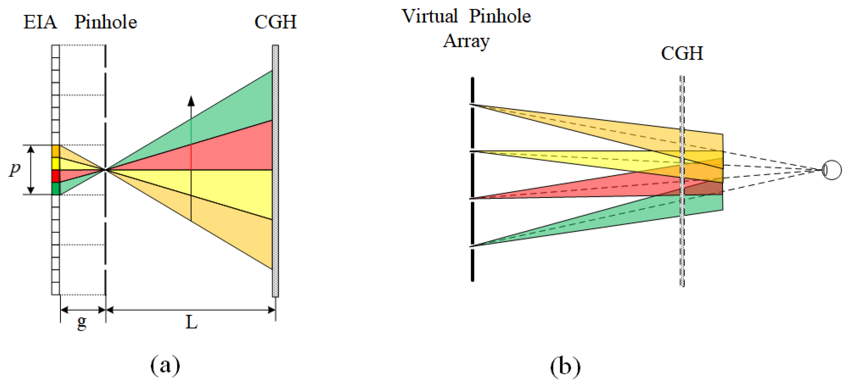
2.1. Pinhole Type HS

Figure 1a shows the principle of the recording process of pinhole-type HSs [21,22]. A 3D object is reconstructed by the pinhole-type integral imaging system [23,24], and the CGH plane is adopted to record the object beam by simulating light propagation from pinholes to CGH. Each pixel of the EI emits a beam of light passing through the corresponding pinhole. The EI is projected onto the CGH with a magnification ratio M = L/g. Therefore, each pinhole can be seen as a point light source emitting different pyramid-shaped light rays in different directions. The intensity of each light ray is determined by the corresponding pixel of EI. To the center pinhole, the recorded complex amplitude U(x, y) on the CGH can be expressed as the multiplication of the spherical wave phase u(x, y) and the projected EI:
U ( x , y ) = u ( x , y ) · p r o j [ E I ( x , y ) ] , u ( x , y ) = 1 R exp ( i 2 π λ R ) .
where R is the distance between the center pinhole (xp, yp) and a coordinate (x, y) on the CGH, EI(x,y) is the original EI, and proj[] is the projection operator of each EI. The projection of each EI can be simply obtained by rotating it by 180 degrees and magnifying the rotated image by interpolation or simple replication. For other pinholes, the recorded complex amplitude can be obtained by shifting the spherical wave phase u(x,y) and multiplying it with the corresponding projected EI. Then, the total diffraction pattern on the CGH Utotal(x,y) can be obtained by adding them together:
U t o t a l ( x , y ) = m = N / 2 N / 2 n = N / 2 N / 2 u ( x m p , y n p ) · p r o j [ E I m , n ( x , y ) ]
where m and n are the sequence numbers of EI in the direction of x and y, p is the pinhole pitch, and N is the number of EI in one dimension.
During the process of reproduction, the pinhole-type HS will reconstruct the recorded light rays, as well as the virtual pinhole array. As shown in Figure 1b, when the observer sees through the hologram, he is actually seeing the 3D image through the reproduced virtual pinhole array. It is a very similar situation to that of PII. That is, the observer’s eye samples a beam of light rays from each virtual or real pinhole, so that the resolution is determined by the pinhole number.
Assuming there are N × N multi-view images each with N0 × N0 pixels, the total computational amount is M2 × N2 × N02, where M = L/g is the magnification ratio. It can be seen from the formula that the calculation time is closely related to the number of EI and the pixel number of each EI. The calculation speed of this method is already fast, in some cases this method is even faster than the FFT-based method [17]. However, in the NED, considering issues such as weight, heat and power consumption, the computing power is usually insufficient. Therefore, the computing speed needs to be further improved.

2.2. Proposed Methods

Due to the limited computation power of a NED device, the algorithm of CGH need to be improved. In this paper, we propose two methods based on the characteristics of the human eye in NEDs to further accelerate the generation of the pinhole-type HS. In the first method, we consider the relatively fixed position of the human eye in NEDs [25]. Since the pupil size of a human eye is small, only part of the wavefront emitted from one EI can be observed. Therefore, the number of pixels of each EI needed to be calculated is greatly reduced. In the second method, the foveated region rendering method is adopted to further enhance the calculation speed [26,27,28,29]. Since the angular resolution of the human eye linearly declines with the increasing visual eccentricity, we reduced the pinhole numbers of the edge area. This means the number of EIs is naturally reduced. In a word, the first method can reduce the number of pixels in each EI, and another method is used to reduce the number of EIs. In addition, these two methods can be used in parallel to further improve the calculation speed.

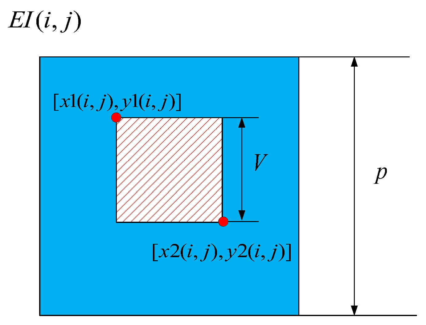
2.2.1. Calculation Acceleration Based on Visible Pixels

As mentioned in Section 2.1, in conventional pinhole-type holographic display, the observer’s eye only samples one light ray from each virtual pinhole. However, to ensure that the human eye can move freely in a large area, the wavefront emitted from each EI should be completely calculated. Once the pinhole-type HS is adopted in a NED, the situation is changed. Due to the relative fixed-eye position of the NED, only part of the wavefront emitted from one EI can be observed. This part of wavefront is usually emitted from several pixels of each EI. In other words, only part of the pixels of each EI can be observed which can be called visible pixels.
Figure 2 shows the principle of the proposed method. A wavefront recording plane near the pinhole array is set here to decrease the computation amount [21]. In NEDs, the human eye is generally close the hologram. Thus, the human eye usually needs to observe a virtual image through the hologram. Moreover, the range of human eye movement is limited in a small viewing window. Through the limited viewing window, only part of the pixels of each EI can be observed, which can be called visible pixels. This area of visible pixels on each EI can be defined according to the projection relationship:
V = g R + Z + L W
where g is the gap between the EIA and the pinhole array, L is the distance between the pinhole and the wavefront recording plane, Z is the distance between the wavefront recording plane and the SLM, R is the eye relief which means the distance between the SLM and the VW, V is the size of the visible region, and W is the size of VW. Thus, the ratio of the visible area to EI can be easily obtained:
r v = V / p
where p is the size of each EI. As the number of the visible pixels decreases, the computed burden can be reduced. Thus, the computation account is rv2M2N2N02 now after using the proposed method. In theory, only the part of wavefront entering the pupil of an observing eye is effective, which means only the wavefront of the pupil size needs to be calculated. Usually, the pupil size of the human eye is 2 mm. Considering the rotation and shift of human eye, a practical viewing window should be larger than the pupil size so that the eye can still receive the wavefront when moving in the range. In this case, usually only a few pixels need to be calculated for each EI and the time cost is greatly reduced.
In the proposed method, for each EI, the position of visible pixels is disparate. Thus, it takes extra time to calculate the position of visible pixels. To reduce this part of computing consumption, we used a look-up table method, as Figure 3 shows. For (i,j)-th EI, the boundary position of the visible area can be simply calculated according to the geometric relationship. During the calculating process of the hologram, we just need to take out the corresponding visible pixels according to the position information of each EI. Although this process still requires some additional time, it is insignificant compared to the overall calculation speed increase.

2.2.2. Calculation Acceleration Based on Foveated Region Rendering

In the second proposed method, the foveated region rendering technology was adopted to improve the calculation speed. There are already several papers reporting the acceleration of the generation of wave-based CGH using the foveated region rendering, but we have not seen any reports on the application of this method to a ray-based CGH method [26,27,28,29]. In this paper, we propose using the foveated region rendering to speed up the generation of pinhole-type HS.
It is a common experience that one can obtain the sharp detail only in the viewing direction, but the surrounding is less distinct. This is because of the variation in the photoreceptor density at the retina. Visual acuity represents the ability of visual resolution, which can be measured by a minimum angle of resolution (MAR) [26]. Based on that measure, the visual acuity can be explained by linear model. Such a linear model can be expressed by:
ω = m e + ω 0
where ω is the MAR in degrees per cycle, e is the eccentricity angle, ω0 is the smallest resolvable angle and represents the reciprocal of visual acuity at the fovea (e = 0), and m is the MAR slope. Equation (5) can be depicted by the blue line in Figure 4a, which denotes the angular resolution linearly declining with the increasing visual eccentricity.
In a conventional PII-based holographic display, the observer’s eye samples light rays from virtual pinholes. Sufficient pinholes are uniformly set to obtain a superior viewing experience. The sampling interval of the reconstructed images observed by the human eye depends on the interval between the pinholes, and the spatial resolution of reconstructed images is determined by the pinhole number. However, according to the visual acuity of the human eye, the edge area does not require high resolution. Therefore, we appropriately reduced the number of pinholes in the edge area and increased the pinhole spacing to improve the generation speed of our pinhole-type HS.
Figure 4 shows the principle of the proposed method, to account for (considering) the visual acuity of the human eye, we separated the pinhole array into several regions. Assuming that pinhole array is separated by I circular regions with radii r1, r2, …, and ri (r0 = 0), the pinhole spacing in i-th region is increased to tn*p. Thus, the pinhole number of i-th region is about:
k i = π ( r i 2 r i 1 2 ) ( t n p ) 2
and the total pinhole number can be easily obtained:
k t o t a l = 1 I π ( r i 2 r i 1 2 ) ( t n p ) 2
where i is the sequence number of different regions. Thus, the calculation amount of this method is M2 × ktotal × N02. This means the calculation speed can be improved by ktotal/N2 times.

3. Results

Numerical simulation was performed to verify the proposed methods. Firstly, for comparison, the simulation of the conventional pinhole-type HS was performed. For simplicity, a 2D object was set and a virtual camera array was built to capture the EIA of the 2D scene. The camera array consisted of 400 × 400 virtual pinhole cameras, and the pitch and focal length were set as p = 0.05 mm and g = 0.2 mm. Figure 5a shows the original object and Figure 5b shows the captured EIA which contained 10,000 × 10,000 pixels with 2 µm pixel pitch. The recording hologram plane was set 0.2 mm distant from the pinhole array to record the complex amplitude of the pinholes. The pixel number of the hologam was 10000 × 10000, the pixel size was set as 2 µm, the size of hologram was 20 mm and the wavelength was set as 532 nm. In this case, the magnification ratio was 1. The short recording distance was to ensure the fast computing speed. The position of the human eye was set 7 cm distant from the hologram. Thus, the field of view angle was calculated as 2 × tan-1(10/70) ≈ 16°. Figure 6 shows the reconstructed image of the conventional pinhole-type HS. Using the MATLAB R2016b with an intel i7-8700 (3.2 GHz) and a memory of 32 Gbytes, the generation time of the conventional pinhole-type HS generation was about 2.17 s, while the conventional FFT-based HS generation took about 2.59 s, which performed 400 × 400 FFT calculations.
Then, the numerical simulation of the visible pixels method was performed. The eye movement range was set as 4 mm and pupil size was set as 2 mm. From Equation (3), only 3 × 3 pixels needed to be calculated. Figure 7 shows the reconstructed image of the proposed method using visible pixels. It can be seen that the quality of the images of the proposed method using visible pixels was almost the same as the original method, but the calculation speed was greatly improved. The generation time was 337 ms, which meant the calculation speed was increased by about 6.2 times. The PSNR and SSIM between the original image and the reconstructed image of conventional pinhole type HS were 17.06 and 0.5575, respectively. The PSNR and SSIM between the original image and the reconstructed image of the proposed visible pixle method were 15.9 and 0.5328, respectively. This proves that the proposed visible pixels method can effectively accelerate the calculation speed of CGH without too much image quality degeneration.
Next, the simulation of the proposed method based on the foveated region rendering was performed. For simplicity, the pinholes were divided into two regions. The angle range of foveated region was set as 4°; thus, the radii of the foveated region and peripheral region were 0.25 cm and 1 cm, respectively. The pinhole spacing of these two regions were 0.05 mm and 0.1 mm, respectively. Figure 8 shows the reconstructed image. We can see that the center part of the image remains unchanged, and the image quality of the peripheral region was slightly decreased. The PSNR and SSIM between the original image and the reconstructed image of the foveated region rendering method were 10.9763 and 0.5297, respectively. As the sampling rate of the peripheral region reduced, some black gaps could be seen after magnification, so the PSNR was decreased significantly; however, because the overall structure of the image was not damaged, the SSIM was not significantly decreased. The calculation time was 638 ms, and the speed-up ratio was 3.4 times, which was consistent with the theoretical value.
Finally, a simulation based on the simultaneous use of two methods. Figure 9 shows the result. The reconstructed image is also similar to Figure 8. The calculation time was about 102 ms, and the calculation time was reduced by about 20 times. This is a very fast speed. Since we just used one of the eight CPU threads, the calculation time can be further reduced to achieve real-time processing by using the eight CPU threads simultaneously. Using a better CPU or using the GPU acceleration methods could also further increase the calculation speed.
We further demonstrated the proposed methods of a 3D object. For simplicity, we set a 3D scene containing two images at different planes, as Figure 10a,b show. These two planes were set −2 mm and 2 mm distant from the pinhole plane. Figure 10c,d show the reconstructed images of the conventional pinhole-type HS focus on the pattern and letters, respectively. Figure 11 shows the reconstructed results of the proposed visible pixels method. The reconstructed results were basically consistent with the traditional method, the difference was that because the proposed method reduced the beam width, similar to the Maxwellian-type holographic display [30,31], the depth-of-field range of each layer was increased. This can be easily confirmed from the enlarged details of the red boxes and the blue boxes. Figure 12 shows the reconstructed results of the foveated region rendering method. We set the second layer of the letters as the peripheral region. From the enlarged details in Figure 12, the quality of the central pattern remained unchanged and the image quality of the peripheral letters was slightly decreased. The simulations prove that the proposed methods are effective for 3D objects. It is worth noting that no matter how many layers there are in a 3D scene, the calculation amount of the proposed methods is the same, since the computational complexity is only related to the total number of pixels that need to be calculated on the captured EIA.

4. Discussion

The time costs of different methods are compared in Table 1. It can be seen that the calculation speed of the pinhole-type HS was indeed faster than the FFT method. With the visible pixels method, the generation time was 337 ms, which meant the calculation speed was increased by about 6.2 times. With the foveated region rendering method, the calculation time was 638 ms and speed-up ratio was 3.4 times. When these two methods were used in parallel, the total improvement was the product of the two methods. With both methods in parallel, the calculation time was about 102 ms. In fact, we only showed the improvement of the hologram computation time in this paper. The proposed methods can also speed up parallax image rendering, since both the number of parallax images and the number of pixels of each parallax image are greatly reduced. Therefore, the proposed methods are beneficial to promote the practical application of holographic near-eye displays.

5. Conclusions

In summary, we proposed two methods based on the characteristics of the human eye in a NED to further accelerate the generation of the pinhole-type HS. In the first method, we considered the relatively fixed position of the human eye in a NED. Since the pupil size of a human eye is small, only part of the wavefront emitted from each EI can be observed. Therefore, the number of pixels of each EI needed to be calculated was greatly reduced. In the second method, the foveated region rendering method was adopted to further enhance the calculation speed. Since the angular resolution of the human eye linearly declined with the increasing visual eccentricity, we reduced the pinhole’s number in the edge area. This meant the number of EIs naturally reduced. Simulations demonstrated that the generation speed of a pinhole-type HS with 10000 × 10000 pixels can be enhanced by about 20 times with the proposed two methods.

Author Contributions

Conceptualization, G.L., Z.W. and Q.F.; methodology, X.Z.; software, X.Z. and T.C.; validation, G.L., Z.W. and Q.F.; writing—original draft preparation, X.Z.; writing—review and editing, X.Z., T.C., Y.P., P.D. and K.T.; supervision, G.L., Z.W. and Q.F.; All authors have read and agreed to the published version of the manuscript.

Funding

National Natural Science Foundation of China (61805065); The Fundamental Research Funds for the Central Universities (JZ2021HGTB0077).

Data Availability Statement

Data underlying the results presented in this paper are not publicly available at this time but maybe obtained from the authors upon reasonable request.

Conflicts of Interest

The authors declare no conflict of interest.

References

  1. He, Z.; Sui, X.; Jin, G.; Cao, L. Progress in virtual reality and augmented reality based on holographic display. Appl. Opt. 2018, 58, A74–A81. [Google Scholar] [CrossRef] [PubMed]
  2. Chen, C.P.; Cui, Y.; Ye, Y.; Yin, F.; Shao, H.; Lu, Y.; Li, G. Wide-Field-of-View Near-Eye Display with Dual-Channel Waveguide. Photonics 2021, 8, 557. [Google Scholar] [CrossRef]
  3. Eunkyong, O.; Myeongjae, K.; Jinyoung, R.; Hwi, K.; Joonku, H. Holographic Head-Mounted Display with RGB Light Emitting Diode Light Source. Opt. Express 2014, 22, 6526–6534. [Google Scholar]
  4. Yasuhiro, T.; Nago, N. Multi-Projection of Lenticular Displays to Construct a 256-View Super Multi-View Display. Opt. Express 2010, 18, 8824–8835. [Google Scholar]
  5. Lanman, D.; Luebke, D. Near-eye light field displays. ACM Trans. Graph. 2013, 32, 1–10. [Google Scholar] [CrossRef]
  6. Wang, Q.; Ji, C.; Li, L.; Deng, H. Dual-view integral imaging 3D display by using orthogonal polarizer array and polarization switcher. Opt. Express 2016, 24, 9–16. [Google Scholar] [CrossRef] [PubMed]
  7. Kaan, A.; Ward, L.; Jonghyun, K.; Peter, S.; David, L. Near-Eye Varifocal Augmented Reality Display Using See-through Screens. ACM Trans. Graph. 2017, 36, 189. [Google Scholar]
  8. Mali, L.; Chihao, L.; Haifeng, L.; Xu, L. Near Eye Light Field Display Based on Human Visual Features. Opt. Express 2017, 25, 9886–9900. [Google Scholar]
  9. Tomoyoshi, S.; Hirotaka, N.; Nobuyuki, M.; Tomoyoshi, I. Rapid Calculation Algorithm of Fresnel Computer-Generated-Hologram Using Look-up Table and Wavefront-Recording Plane Methods for Three-Dimensional Display. Opt. Express 2010, 18, 19504–19509. [Google Scholar]
  10. Kyoji, M.; Nakahara, S. Extremely High-Definition Full-Parallax Computer-Generated Hologram Created by the Polygon-Based Method. Appl. Opt. 2009, 48, H54–H63. [Google Scholar]
  11. Yan, Z.; Cao, L.; Zhang, H.; Kong, D.; Jin, G. Accurate Calculation of Computer-Generated Holograms Using Angular-Spectrum Layer-Oriented Method. Opt. Express 2015, 23, 25440–25449. [Google Scholar]
  12. Wang, Z.; Zhu, L.; Zhang, X.; Dai, P.; Lv, G.; Feng, Q.; Wang, A.; Ming, H. Computer-Generated Photorealistic Hologram Using Ray-Wavefront Conversion Based on the Additive Compressive Light Field Approach. Opt. Lett. 2020, 45, 615–618. [Google Scholar] [CrossRef] [PubMed]
  13. Nishi, H.; Matsushima, K.; Nakahara, S. Smooth shading of specular surfaces in polygon-based high-definition CGH. In Proceedings of the 2011 3DTV Conference: The True Vision—Capture, Transmission and Display of 3D Video (3DTV-CON), Antalya, Turkey, 16–18 May 2011; pp. 1–4. [Google Scholar]
  14. Blinder, D.; Chlipala, M.; Kozacki, T.; Schelkens, P. Photorealistic computer generated holography with global illumination and path tracing. Opt. Lett. 2021, 46, 2188–2191. [Google Scholar] [CrossRef] [PubMed]
  15. Tomoyuki, M.; Makoto, O.; Fumio, O. Calculation of Holograms from Elemental Images Captured by Integral Photography. Appl. Opt. 2006, 45, 4026–4036. [Google Scholar]
  16. Hyeung, P.J.; Su, K.M.; Ganbat, B.; Nam, K. Fresnel and Fourier Hologram Generation Using Orthographic Projection Images. Opt. Express 2009, 17, 6320–6334. [Google Scholar]
  17. Yasuyuki, I.; Ryutaro, O.; Takanori, S.; Kenji, Y.; Taiichiro, K. Real-Time Capture and Reconstruction System with Multiple GPUs for a 3D Live Scene by a Generation from 4K IP Images to 8K Holograms. Opt. Express 2012, 20, 21645–21655. [Google Scholar]
  18. Koki, W.; Masahiro, Y.; Bahram, J. High-Resolution Three-Dimensional Holographic Display Using Dense Ray Sampling from Integral Imaging. Opt. Lett. 2012, 37, 5103–5105. [Google Scholar]
  19. Ichikawa, T.; Yoneyama, T.; Sakamoto, Y. CGH calculation with the ray tracing method for the Fourier transform optical system. Opt. Express 2013, 21, 32019–32031. [Google Scholar] [CrossRef] [Green Version]
  20. Wang, Z.; Lv, G.; Feng, Q.; Wang, A.; Ming, H. Resolution priority holographic stereogram based on integral imaging with enhanced depth range. Opt. Express 2019, 27, 2689–2702. [Google Scholar] [CrossRef]
  21. Wang, Z.; Lv, G.; Feng, Q.; Wang, A.; Ming, H. Simple and Fast Calculation Algorithm for Computer-Generated Hologram Based on Integral Imaging Using Look-up Table. Opt. Express 2018, 26, 13322–13330. [Google Scholar] [CrossRef]
  22. Wang, Z.; Lv, G.; Feng, Q.; Wang, A.; Ming, H. Enhanced resolution of holographic stereograms by moving or diffusing a virtual pinhole array. Opt. Express 2020, 28, 22755–22766. [Google Scholar] [CrossRef] [PubMed]
  23. Kim, Y.; Kim, J.; Kang, J.M.; Jung, J.H.; Choi, H.; Lee, H. Point light source integral imaging with improved resolution and viewing angle by the use of electrically movable pinhole array. Opt. Express 2007, 15, 18253–18267. [Google Scholar] [CrossRef]
  24. Deng, H.; Wang, Q.; Wu, F.; Luo, C.; Liu, Y. Cross-talk-free integral imaging three-dimensional display based on a pyramid pinhole array. Photonics Res. 2015, 3, 173–176. [Google Scholar] [CrossRef]
  25. Chen, Z.; Sang, X.; Lin, Q.; Li, J.; Yu, X.; Gao, X.; Yan, B.; Yu, C.; Dou, W.; Xiao, L. Acceleration for Computer-Generated Hologram in Head-Mounted Display with Effective Diffraction Area Recording Method for Eyes. Chin. Opt. Lett. 2016, 14, 80901–80905. [Google Scholar] [CrossRef]
  26. Jisoo, H.; Youngmin, K.; Sunghee, H.; Choonsung, S.; Hoonjong, K. Gaze Contingent Hologram Synthesis for Holographic Head-Mounted Display. In Practical Holography XXX: Materials and Applications; SPIE: Bellingham, WA, USA, 2016; Volume 9771, p. 97710K. [Google Scholar]
  27. Lingjie, W.; Sakamoto, Y. Fast Calculation Method with Foveated Rendering for Computer-Generated Holograms Using an Angle-Changeable Ray-Tracing Method. Appl. Opt. 2019, 58, A258–A266. [Google Scholar]
  28. Yeon-Gyeong, J.; Park, J. Foveated Computer-Generated Hologram and Its Progressive Update Using Triangular Mesh Scene Model for near-Eye Displays. Opt. Express 2019, 27, 23725–23738. [Google Scholar]
  29. Liang, C.C.; Wei, C.; Liang, G. Foveated Holographic near-Eye 3D Display. Opt. Express 2020, 28, 1345–1356. [Google Scholar]
  30. Wang, Z.; Zhang, X.; Lv, G.; Feng, Q.; Ming, H.; Wang, A. Hybrid holographic Maxwellian near-eye display based on spherical wave and plane wave reconstruction for augmented reality display. Opt. Express 2021, 29, 4927–4935. [Google Scholar] [CrossRef]
  31. Maimone, A.; Georgiou, A.; Kollin, J.S. Holographic near-eye displays for virtual and augmented reality. ACM Trans. Graph. (Tog) 2017, 36, 1–16. [Google Scholar] [CrossRef]
Figure 1. (a) Principle of recording stage of pinhole-type HS; (b) the observer’s eye samples one light ray from each virtual pinhole in the display stage of “pinhole mode”.
Photonics 09 00095 g001
Figure 2. Principle of the visible pixels method.
Photonics 09 00095 g002
Figure 3. Schematic diagram of the visible area.
Photonics 09 00095 g003
Figure 4. (a) The linear model of MAR with respect to eccentricity angle; (b) principle of the foveated region rendering method.
Photonics 09 00095 g004
Figure 5. (a) The original object; (b) the captured EIA using 400 × 400 virtual pinhole cameras.
Photonics 09 00095 g005
Figure 6. The reconstructed image of the conventional pinhole-type HS.
Photonics 09 00095 g006
Figure 7. The reconstructed image of the proposed visible pixels method.
Photonics 09 00095 g007
Figure 8. The reconstructed image of the proposed foveated region rendering method.
Photonics 09 00095 g008
Figure 9. The reconstructed image of both the proposed visible pixels method and the foveated region rendering method.
Photonics 09 00095 g009
Figure 10. The original images that were set at (a) −2 mm and (b) 2 mm distant from the pinhole plane. The reconstructed images of the conventional pinhole-type HS focus on the (c) pattern and (d) letters.
Photonics 09 00095 g010
Figure 11. The reconstructed images of the proposed visible pixels method focus on the (a) pattern and (b) letters.
Photonics 09 00095 g011
Figure 12. The reconstructed images of the proposed foveated region rendering method focus on the (a) pattern and (b) letters.
Photonics 09 00095 g012
Table 1. Time cost of the different method.
The MethodFFT-Based MethodPinhole-Type HSVisible Pixels MethodFoveated Region Rendering MethodVisible Pixels Method and Foveated Region Rendering Method
Time Cost (ms)25902170337638102
Publisher’s Note: MDPI stays neutral with regard to jurisdictional claims in published maps and institutional affiliations.

