Variable Repetition Rate Picosecond Master Oscillator for Photoelectron Gun


Abstract
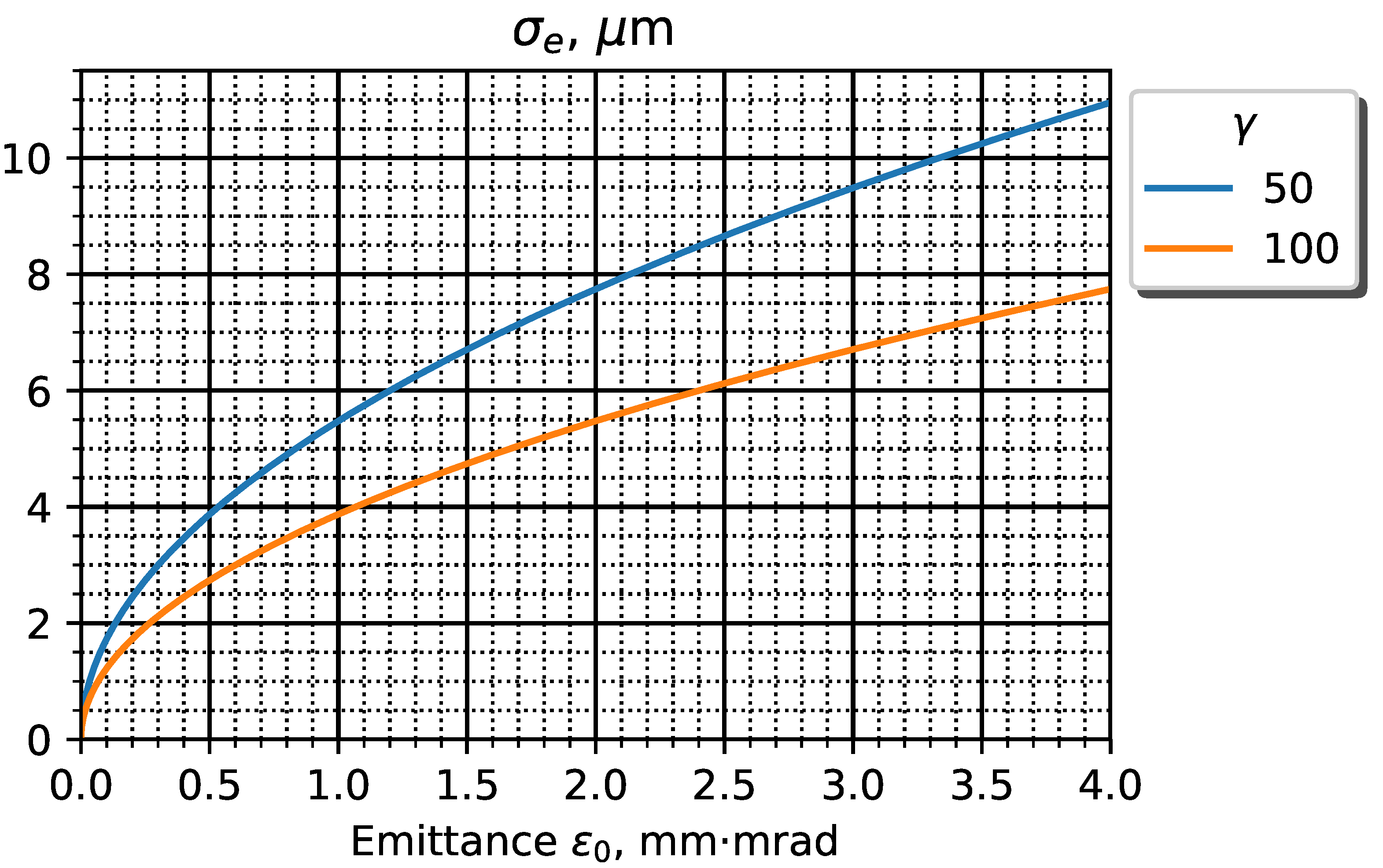
:1. Introduction
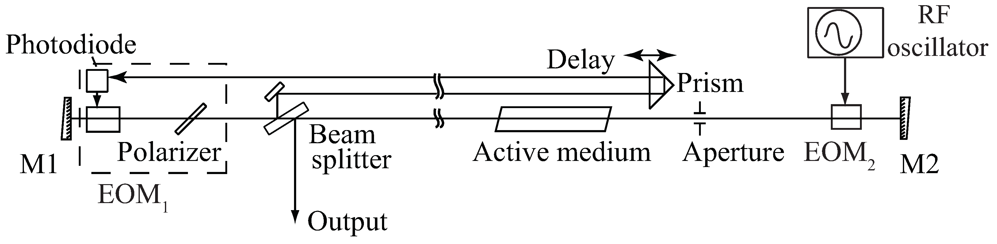
2. Solid-State Laser with Electro-Optical Control and RF Modulation
3. Numerical Model
3.1. Loss and Shaping in EOMs
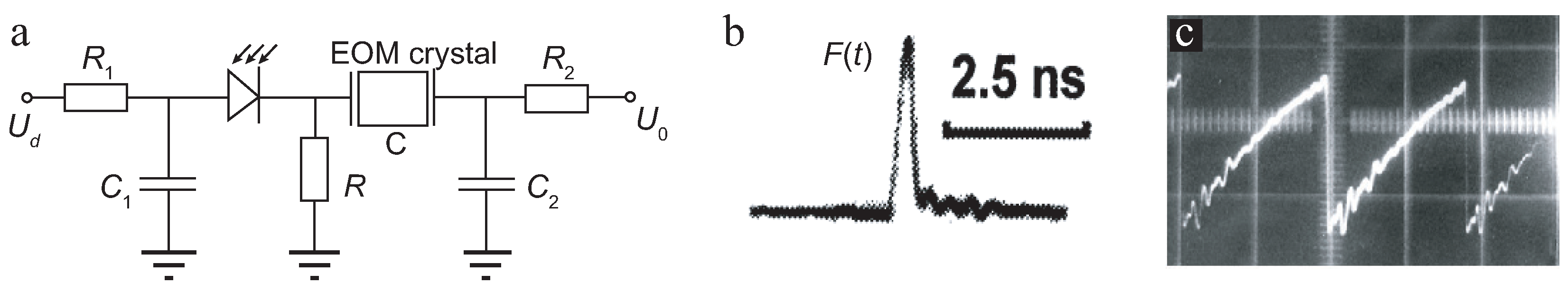
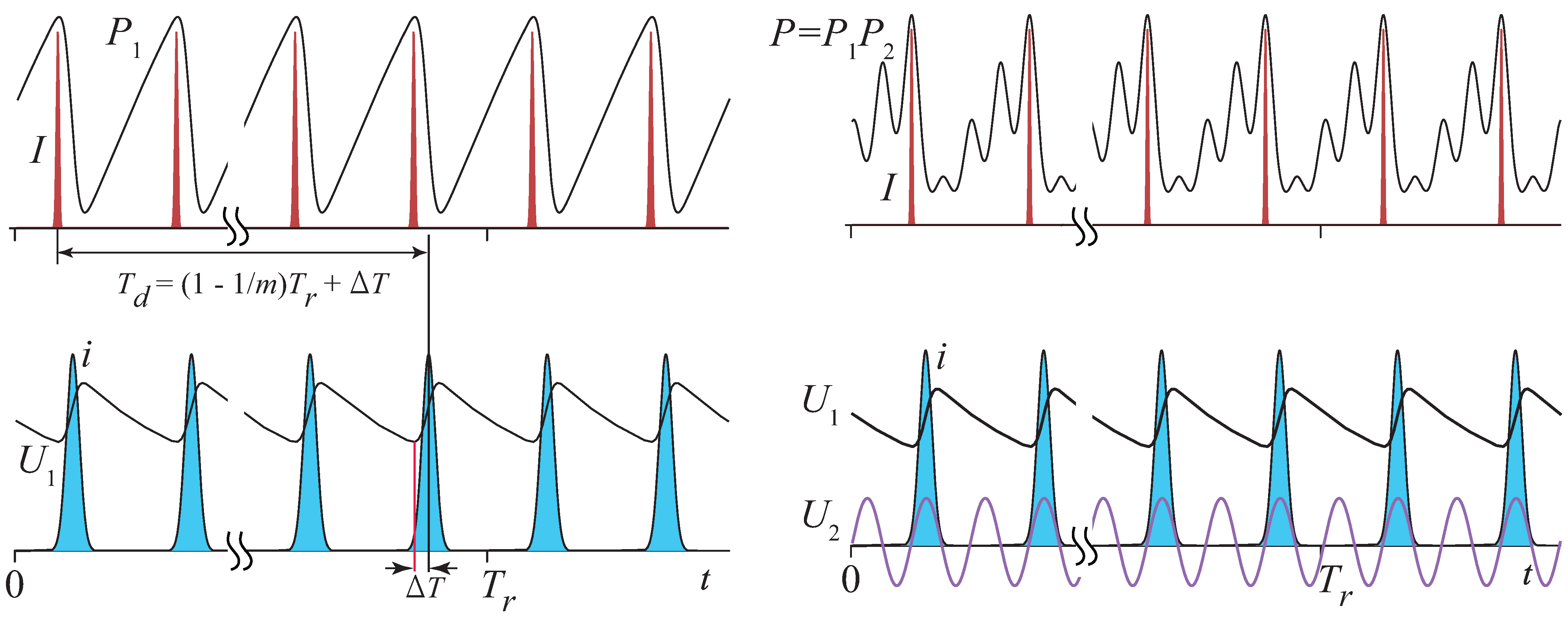
3.1.1. EOM for SSHML
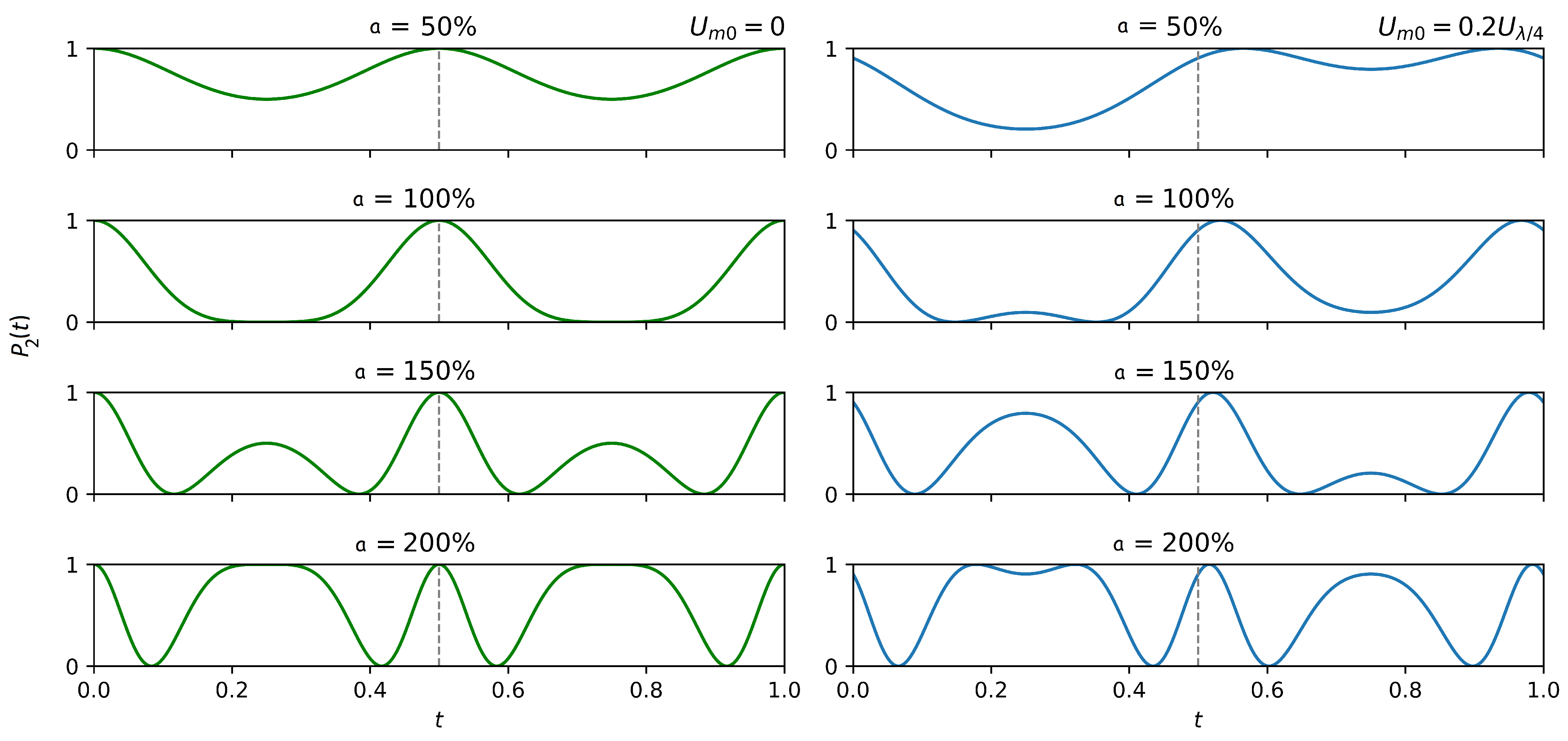
3.1.2. EOM for Synchronization with Accelerator
3.2. Amplification in the Active Medium
3.3. Spontaneous Emission of the Active Medium
3.4. Passive Loss
3.5. Final Form for Amplitude Transformation
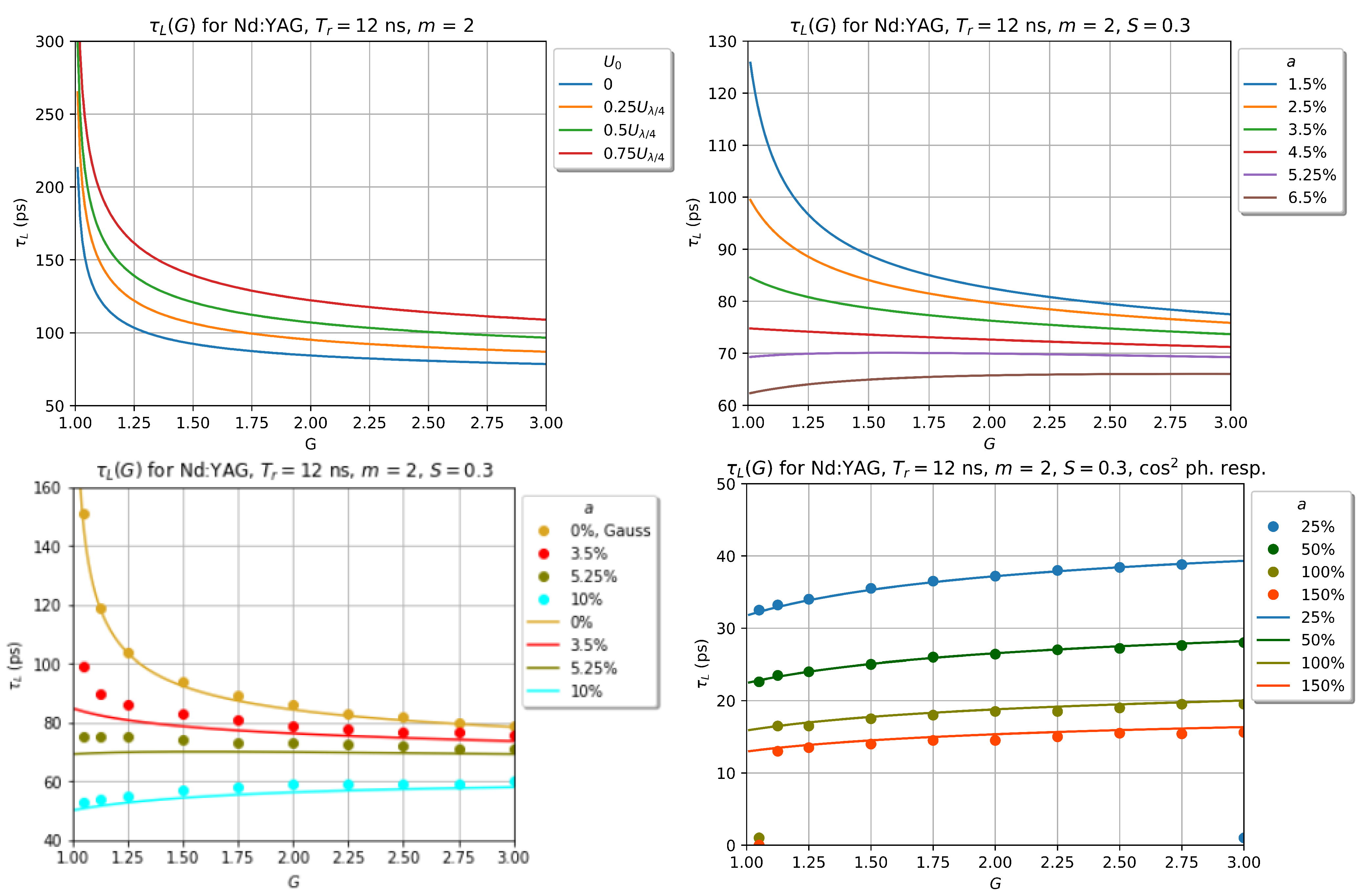
4. Steady-State Analysis
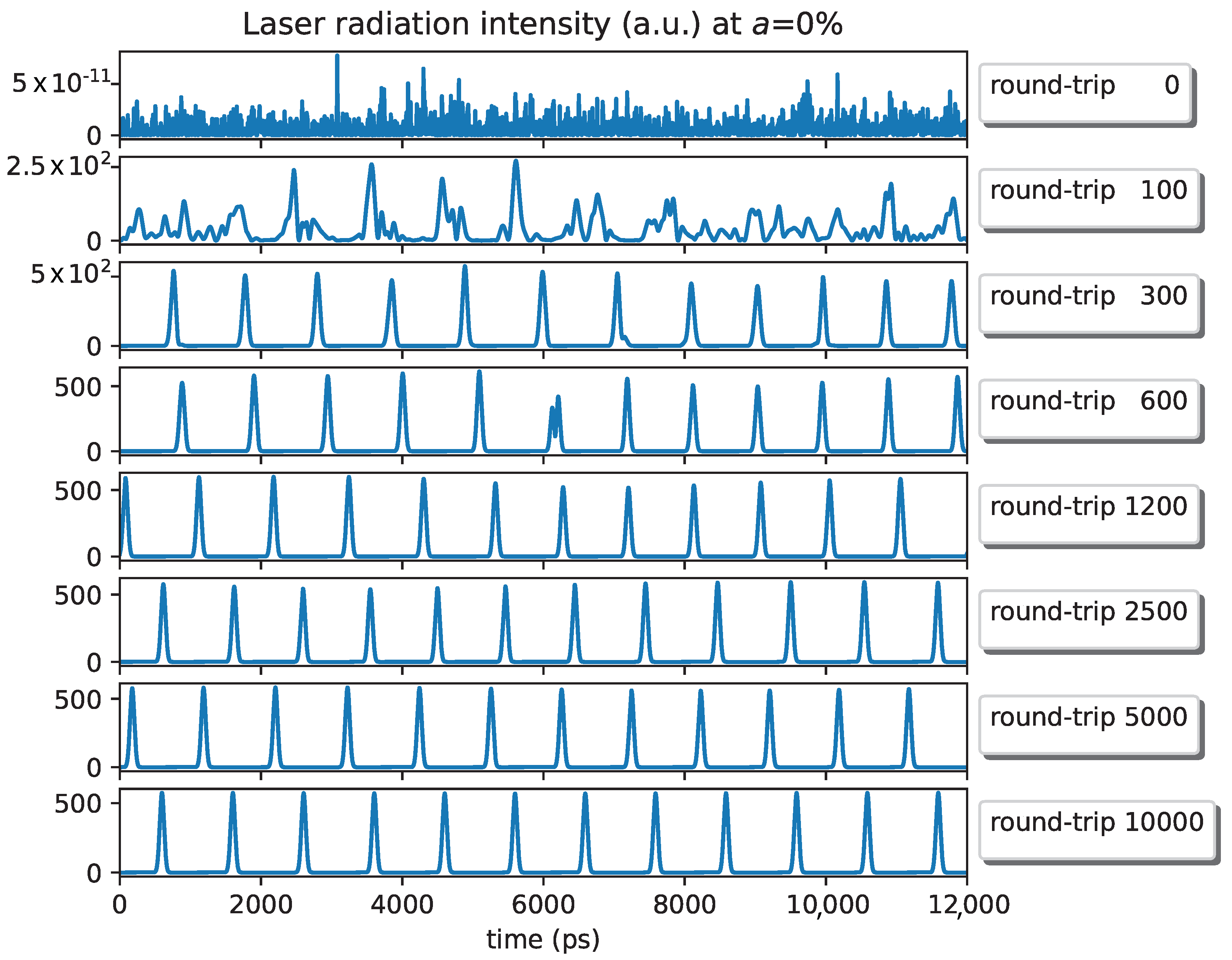
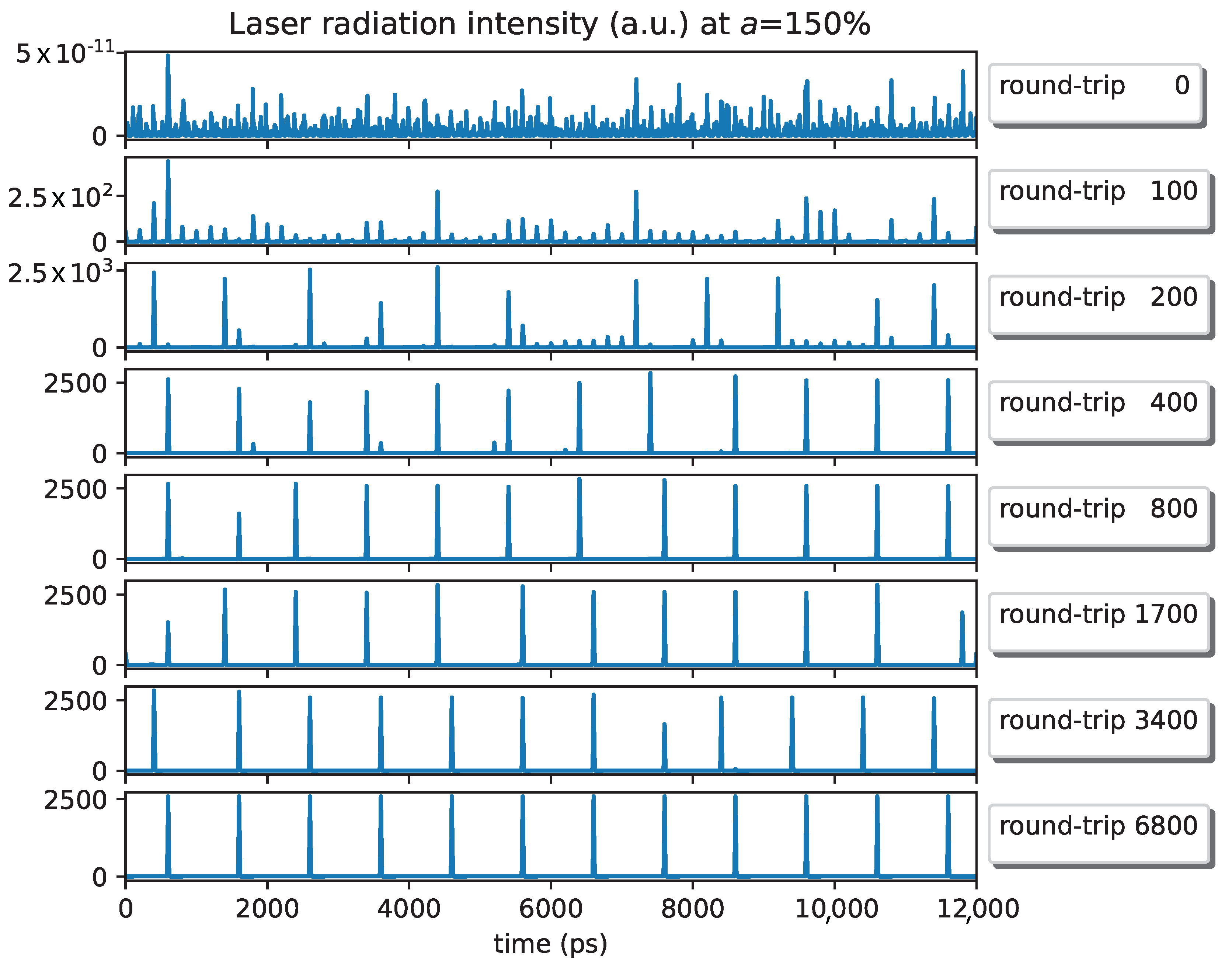
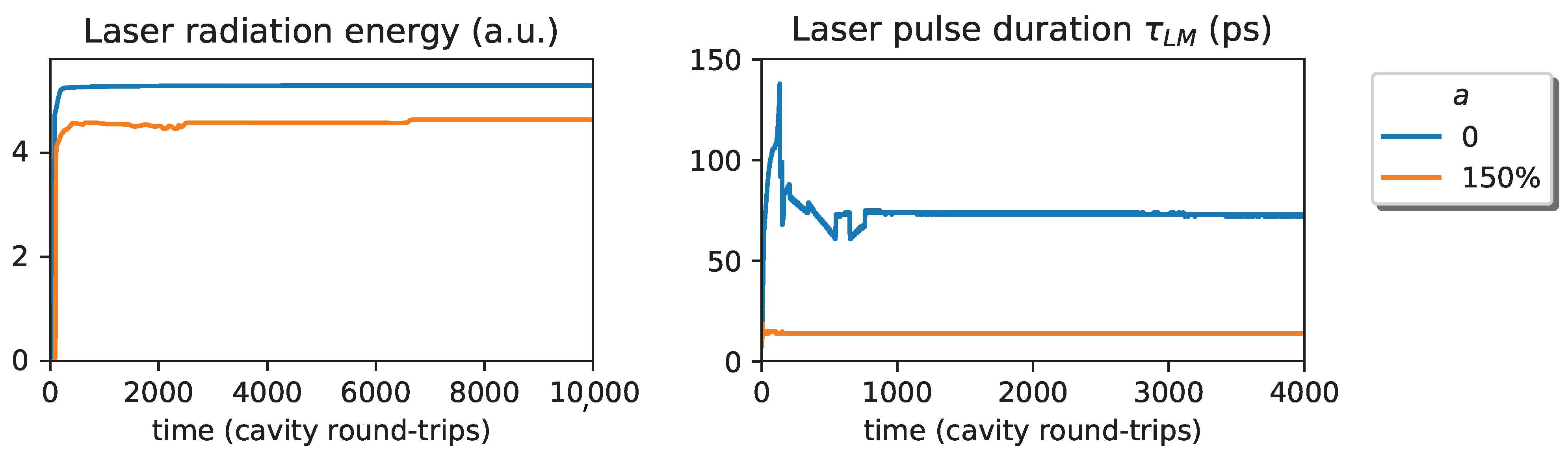
5. Numerical Simulation Results
6. Discussion
7. Conclusions
Author Contributions
Funding
Institutional Review Board Statement
Informed Consent Statement
Data Availability Statement
Acknowledgments
Conflicts of Interest
Abbreviations
| RF | Radio frequency |
| FEL | Free-electron laser |
| HML | Harmonic mode-locking |
| SSHML | Self-starting harmonic mode-locking |
| EOM | Electro-optical modulator |
| NFB | Negative feedback |
| Laser cavity round-trip time | |
| Index L stands for negative-feedback-determined values | |
| Index LM means the combined action of NFB and RF modulation |
Appendix A. Laser Pulse Duration in the Case of SSHML with RF Modulation
References
- Kerse, C.; Kalaycioglu, H.; Elahi, P.; Akcaalan, O.; Ilday, F.O. 3.5-ghz intra-burst repetition rate ultrafast yb-doped fiber laser. Opt. Comm. 2016, 1, 404–409. [Google Scholar] [CrossRef]
- Soibel, A.; Wright, M.; Farr, W.; Keo, S.; Hill, C.; Yang, R.Q.; Liu, H.C. Mid-infrared interband cascade lasers for free-space laser communication. In Proceedings of the Proceedings Volume 7199, Free-Space Laser Communication Technologies XXI, 71990E (2009), San Jose, CA, USA, 24–29 January 2009. [Google Scholar]
- Delfyett, P.; Christopher, D.; Yilmaz, T. Ultralow Noise Optical Clock for High Speed Sampling Aplications. U.S. Patent 2004/6735229 B1, 11 May 2004. [Google Scholar]
- Priebe, G.; Laundy, D.; Phillips, P.J.; Graham, D.M.; Jamison, S.P.; Vassilev, S.; Seddon, E.A.; Rosenzweig, J.B.; Krafft, G.A.; Heinzl, T.; et al. First results from the daresbury compton backscattering X-ray source (cobald). In Proceedings of the Proceedings Volume 7805, Hard X-ray, Gamma-Ray, and Neutron Detector Physics XII, 780513 (2010), San Diego, CA, USA, 1–5 August 2010. [Google Scholar]
- Will, I.; Templin, H.I.; Schreiber, S.; Sandner, W. Photoinjector drive laser of the flash FEL. Opt. Express 2011, 19, 23770–23781. [Google Scholar] [CrossRef] [PubMed] [Green Version]
- Shimizu, H.; Akemoto, M.; Arai, Y.; Araki, S.; Aryshev, A.; Fukuda, M.; Fukuda, S.; Haba, J.; Hara, K.; Hayano, H.; et al. X-ray generation by inverse compton scattering at the superconducting rf test facility. Nucl. Instrum. Methods Phys. Res. Sect. A Accel. Spectrom. Detect. Assoc. Equip. 2015, 772, 26–33. [Google Scholar] [CrossRef]
- Terunuma, N.; Murata, A.; Fukuda, M.; Hirano, K.; Kamiya, Y.; Kii, T.; Kuriki, M.; Kuroda, R.; Ohgaki, H.; Sakaue, K.; et al. Improvement of an s-band rf gun with a cs2te photocathode for the kek-atf. Nucl. Instrum. Methods Phys. Res. Sect. A Accel. Spectrom. Detect. Assoc. Equip. 2010, 613, 1–8. [Google Scholar] [CrossRef]
- Bessonov, E.G.; Gorbunkov, M.V.; Ishkhanov, B.S.; Kostryukov, P.V.; Maslova, Y.Y.; Shvedunov, V.I.; Tunkin, V.G.; Vinogradov, A.V. Laser-electron generator for x-ray applications in science and technology. Laser Part. Beams 2008, 26, 489–495. [Google Scholar] [CrossRef]
- Veisman, M.K.; Andreev, N.E. Dependence of emittance on the length of the electron bunch during laser- plasma acceleration in guiding structures. Kvantovaja Elektron. 2020, 50, 392–400. [Google Scholar] [CrossRef]
- Krasilnikov, M.; Stephan, F.; Asova, G.; Grabosch, H.J.; Groß, M.; Hakobyan, L.; Isaev, I.; Ivanisenko, Y.; Jachmann, L.; Khojoyan, M.; et al. Experimentally minimized beam emittance from an L-band photoinjector. Phys. Rev. Spec.-Top.-Accel. Beams 2012, 15, 100701. [Google Scholar] [CrossRef] [Green Version]
- Kienle, F.; Chen, K.K.; Alam, S.U.; Gawith, C.B.; Mackenzie, J.I.; Hanna, D.C.; Richardson, D.J.; Shepherd, D.P. High-power, variable repetition rate, picosecond optical parametric oscillator pumped by an amplified gain-switched diode. Opt. Express 2010, 18, 7602–7610. [Google Scholar] [CrossRef] [Green Version]
- Fu, Q.; Wu, Y.; Liang, S.; Shardlow, P.C.; Shepherd, D.P.; Alam, S.U.; Xu, L.; Richardson, D.J. Controllable duration and repetition-rate picosecond pulses from a high-average-power OP-GaAs OPO. Opt. Express 2020, 28, 32540–32548. [Google Scholar] [CrossRef]
- Becker, M.; Kuizenga, D.; Siegman, A. Harmonic mode locking of the Nd:YAG laser. IEEE J. Quantum Electron. 1972, 8, 687–693. [Google Scholar] [CrossRef]
- Koo, J.; Park, J.; Lee, J.; Jhon, Y.M.; Lee, J.H. Femtosecond harmonic mode-locking of a fiber laser at 3.27 GHz using a bulk-like, MoSe2 based saturable absorber. Opt. Express 2016, 24, 10575–10589. [Google Scholar] [CrossRef] [PubMed]
- Lecaplain, C.; Grelu, P. Multi-gigahertz repetition-rate-selectable passive harmonic mode locking of a fiber laser. Opt. Exp. 2013, 21, 10897–10902. [Google Scholar] [CrossRef] [PubMed]
- Hao, Q.; Wang, Y.; Luo, P.; Hu, H.; Zeng, H. Self-starting dropout-free harmonic mode-locked soliton fiber laser with a low timing jitter. Opt. Lett. 2017, 42, 2330–2333. [Google Scholar] [CrossRef] [PubMed]
- Peng, J.; Zhan, L.; Luo, S.; Shen, Q. Passive harmonic mode-locking of dissipative solitons in a normal-dispersion Er-doped fiber laser. J. Lightwave Technol. 2013, 31, 3009–3014. [Google Scholar] [CrossRef]
- Mao, Y.; Tong, X.; Wang, Z.; Zhan, L.; Hu, P.; Chen, L. Wavelength tunable 10 GHz actively harmonic mode-locked fiber laser based on semiconductor optical amplifier. App. Phys. B 2015, 121, 517–521. [Google Scholar] [CrossRef]
- Li, W.; Yin, Z.; Qiu, J.; Wu, J.; Lin, J. Tunable active harmonic mode-locking Yb-doped fiber laser with all-normal dispersion. IEEE Phot. Techn. Lett. 2013, 25, 2247–2250. [Google Scholar] [CrossRef]
- Gorbunkov, M.V.; Konyashkin, A.V.; Kostryukov, P.V.; Morozov, V.B.; Olenin, A.N.; Rusov, V.A.; Telegin, L.S.; Tunkin, V.G.; Shabalin, Y.V.; Yakovlev, D.V. Pulsed-diode-pumped, all-solid-state, electro-optically controlled picosecond Nd:YAG lasers. Quantum Electron. 2005, 35, 2. [Google Scholar] [CrossRef]
- Scott, R.P.; Bennet, C.V.; Kolner, B.H. AM and high-harmonic FM laser mode-locking. Appl. Opt. 1997, 36, 5908–5912. [Google Scholar] [CrossRef]
- Godil, A.A.; Hou, A.S.; Auld, B.A.; Bloom, D.M. Harmonic mode-locking of a Nd:BEL laser using a 20-GHz dielectric resonator/optical modulator. Opt. Lett. 1991, 16, 1765–1767. [Google Scholar] [CrossRef]
- Longhi, S.; Laporta, P.; Taccheo, S.; Svelto, O. Third-order-harmonic mode-locking of a bulk erbium:ytterbium:glass laser at a 2.5 GHz repetition rate. Opt. Lett. 1994, 19, 1985–1987. [Google Scholar] [CrossRef]
- Hughes, D.W.; Barr, J.R.M.; Hanna, D.C. Mode locking of a diode-laser-pumped Nd:glass laser by frequency modulation. Opt. Lett. 1991, 16, 147–149. [Google Scholar] [CrossRef] [PubMed] [Green Version]
- Gorbunkov, M.V.; Maslova, Y.Y.; Tunkin, V.G.; Shabalin, Y.V.; Yakovlev, D.V. Application of optoelectronic negative feedback to ordering of the temporal structure of the diode-pumped nd:ylf laser radiation. Bull. Lebedev Phys. Inst. 2016, 43, 217–222. [Google Scholar] [CrossRef]
- Gorbunkov, M.V.; Maslova, Y.Y.; Shabalin, Y.V.; Tunkin, V.G. Analysis of Self-Starting Harmonic Mode-Locking in an Electro-Optic-Feedback Laser. IEEE J. Quantum Electron. 2021, 57, 1–8. [Google Scholar] [CrossRef]
- Gorbunkov, M.V.; Maslova, Y.Y.; Shabalin, Y.V. On master oscillator of laser-electron x-ray generator. J. Russ. Laser Res. 2019, 40, 547–553. [Google Scholar] [CrossRef]
- Gorbunkov, M.; Maslova, Y.; Vinogradov, A. Optical unit of laser-electron x-ray generator designed for medical applications. Nucl. Instrum. Methods Phys. Res. Sect. A Accel. Spectrom. Detect. Assoc. Equip. 2009, 608, S32–S35. [Google Scholar] [CrossRef]
- Gorbunkov, M.; Shabalin, Y. Two-loop feedback controlled laser: New possibilities for ultrashort pulses generation and high-level stabilization. In Proceedings of the Proceedings Volume 4751, ICONO 2001: Nonlinear Optical Phenomena and Nonlinear Dynamics of Optical Systems, Minsk, Belarus, 26 June–1 July 2001. [Google Scholar]
- Herrmann, J.; Wilhelmi, B. Lasers for Ultrashort Light Pulses; Academie: Berlin, Germany, 1987. [Google Scholar]
- Smith, P. Mode-locking of lasers. Proc. IEEE 1970, 58, 1342–1357. [Google Scholar] [CrossRef]
- Penzkofer, A. Solid state lasers. Progr. Quant. Electr. 1988, 12, 291–427. [Google Scholar] [CrossRef]
- Druon, F.; Boudeile, J.; Zaouter, Y.; Hanna, M.; Balembois, F.; Georges, P.; Petit, J.; Golner, P.; Viana, B. New yb-doped crystals for high-power and ultrashort lasers. In Proceedings of the Proceedings Volume 6400, Femtosecond Phenomena and Nonlinear Optics III, 64000D (2006), Stockholm, Sweden, 11–14 September 2006. [Google Scholar]
- Brown, W.J.; Hartemann, F.V. Brightness Optimization of Ultra-Fast Thomson Scattering X-ray Sources. AIP Conf. Proc. 2004, 737, 839–845. [Google Scholar]
- Artyukov, I.A.; Bessonov, E.G.; Feshchenko, R.M.; Gorbunkov, M.V.; Maslova, Y.Y.; Popov, N.L.; Dyachkov, N.V.; Postnov, A.A.; Vinogradov, S.L.; Vinogradov, A.V. Design study of Thomson Laser-Electron X-ray Generator (LEX) for Millisecond Angiography. IOP Conf. Ser. J. Phys. Conf. Ser. 2017, 784, 012002. [Google Scholar] [CrossRef] [Green Version]


| Active Media | , nm | cm | , THz | , ps | ||||
|---|---|---|---|---|---|---|---|---|
| 1 GHz | 3 GHz | 5 GHz | 10 GHz | |||||
| Nd:YAG | 1064.1 | 88 | 0.12 | 71, 54, | 45, 32, | 35, 25, | 25, 18, | |
| 39, 32 | 23, 19 | 18, 14 | 13, 10 | |||||
| Nd:YLF | E⊥c | 1053 | 12 | 0.42 | 38, 29, | 24, 17, | 19, 13, | 13, 9.5, |
| 21, 17 | 12, 10 | 9.5, 7.7 | 6.7, 5.5 | |||||
| E‖c | 1047 | 18 | 0.48 | 36, 27, | 23, 16, | 18, 13, | 13, 8.9, | |
| 20, 16 | 11, 9.4 | 8.9, 7.2 | 6.3, 5.1 | |||||
| Nd:YAP | 1079.5 | 37 | 0.60 | 32, 24, | 20, 14, | 16, 11, | 11, 7.9, | |
| 18, 14 | 10, 8.4 | 7.9, 6.5 | 5.6, 4.6 | |||||
| Nd:BEL | E‖X | 1069.8 | 15 | 0.90 | 26, 20 | 16, 12 | 13, 9.2 | 9.2, 6.5 |
| 14, 12 | 8.4, 6.8 | 6.5, 5.3 | 4.6, 3.7 | |||||
| E‖Y | 1079 | 10 | 3.00 | 14, 11 | 9.0, 6.5 | 7.1, 5.0 | 5.0, 3.6 | |
| 7.9, 6.5 | 4.6, 3.7 | 3.6, 2.9 | 2.5, 2.1 | |||||
| Nd glass | LG-760 | 1054 | 4.3 | 5.28 | 11, 8.2, | 6.8, 4.9, | 5.3, 3.8, | 3.8, 2.7, |
| 5.9, 4.9 | 3.5, 2.8 | 2.7, 2.2 | 1.9, 1.5 | |||||
| LG-680 | 1061 | 2.7 | 7.41 | 9.1, 6.9, | 5.7, 4.1, | 4.5, 3.2 | 3.2, 2.3, | |
| 5.0, 4.1 | 2.9, 2.4 | 2.3, 1.8 | 1.6, 1.3 | |||||
| Active Media | , nm | c | , THz | , ps | |||
|---|---|---|---|---|---|---|---|
| 1 GHz | 3 GHz | 5 GHz | 10 GHz | ||||
| Yb:YAG | 1031 | 2.1 | 2.5 | 21, 16, | 13, 9.4, | 10, 7.3, | 7.3, 5.2, |
| 11, 9.4 | 6.7, 5.4 | 5.2, 4.2 | 3.7, 3.0 | ||||
| Yb:KGW | 1023 | 2.8 | 7.2 | 13, 9.4, | 7.8, 5.5, | 6.1, 4.3, | 4.3, 3.0, |
| 6.8, 5.5 | 3.9, 3.2 | 3.0, 2.5 | 2.2, 1.8 | ||||
| Yb:CaF | 1047 | 0.25 | 8.2 | 12, 8.8, | 7.3, 5.2, | 5.7, 4.0, | 4.0, 2.9, |
| 6.3, 5.2 | 3.7, 3.0 | 2.9, 2.3 | 2.0, 1.6 | ||||
| Yb:glass | 1020 | 0.05 | 10 | 11, 8.0, | 6.6, 4.7, | 5.1, 3.7, | 3.7, 2.6, |
| 5.7, 4.7 | 3.3, 2.7 | 2.6, 2.1 | 1.8, 1.5 | ||||
| Yb:BOYS | 1025 | 0.3 | 17 | 8.2, 6.1, | 5.1, 3.6, | 3.9, 2.8, | 2.8, 2.0, |
| 4.4, 3.6 | 2.6, 2.1 | 2.0, 1.6 | 1.4, 1.1 | ||||
| Yb:CALGO | 1050 | 0.8 | 22 | 7.2, 5.4, | 4.5, 3.2 | 3.5, 2.5, | 2.5, 1.7, |
| 3.9, 3.2 | 2.2, 1.8 | 1.7, 1.4 | 1.2, 1.0 | ||||
| Parameter | Notation | Value |
|---|---|---|
| Laser cavity round-trip time | 12 ns | |
| Active media | Nd:YAG | |
| Emission bandwidth | 0.12 THz | |
| Beam splitter reflection coef. | S | 0.3 |
| Photodiode response time | 500 ps | |
| Modulator bias voltage | 0 | |
| Total gain | G | 1.5 |
| m | , ps | [], ps | , ps | , ps, at given a | |||
|---|---|---|---|---|---|---|---|
| 25% | 50% | 100% | 150% | ||||
| 2 | 6000 | [6350; 6550] | 81 | ||||
| 3 | 4000 | [8330; 8520] | 75 | ||||
| 4 | 3000 | [9340; 9520] | 75 | ||||
| 5 | 2400 | [10,040; 10,080] | 79 | 35 | 25 | 17 | 14 |
| 6 | 2000 | [10,410; 10,470] | 75 | ||||
| 10 | 1200 | [11,140; 11,180] | 68 | ||||
| 12 | 1000 | [11,330; 11,340] | 68 | ||||
Publisher’s Note: MDPI stays neutral with regard to jurisdictional claims in published maps and institutional affiliations. |
© 2022 by the authors. Licensee MDPI, Basel, Switzerland. This article is an open access article distributed under the terms and conditions of the Creative Commons Attribution (CC BY) license (https://creativecommons.org/licenses/by/4.0/).
Share and Cite
Gorbunkov, M.V.; Maslova, Y.Y.; Shabalin, Y.V.; Tunkin, V.G. Variable Repetition Rate Picosecond Master Oscillator for Photoelectron Gun. Photonics 2022, 9, 106. https://doi.org/10.3390/photonics9020106
Gorbunkov MV, Maslova YY, Shabalin YV, Tunkin VG. Variable Repetition Rate Picosecond Master Oscillator for Photoelectron Gun. Photonics. 2022; 9(2):106. https://doi.org/10.3390/photonics9020106
Chicago/Turabian StyleGorbunkov, Mikhail V., Yulia Y. Maslova, Yurii V. Shabalin, and Vladimir G. Tunkin. 2022. "Variable Repetition Rate Picosecond Master Oscillator for Photoelectron Gun" Photonics 9, no. 2: 106. https://doi.org/10.3390/photonics9020106