Article

Relaxation of Beam Irradiation Accuracy of Cooperative Optical Wireless Power Transmission in Terms of Fly Eye Module with Beam Confinement Mechanism

Laboratory for Future Interdisciplinary Research of Science and Technology (FIRST), Institute of Innovative Research (IIR), Tokyo Institute of Technology, R2-39, 4259 Nagatsuta, Midori-ku, Yokohama 226-8503, Japan
*
Author to whom correspondence should be addressed.
Photonics 2022, 9(12), 995; https://doi.org/10.3390/photonics9120995
Submission received: 5 October 2022 / Revised: 9 November 2022 / Accepted: 7 December 2022 / Published: 16 December 2022

Abstract

:
In optical wireless power transmission (OWPT) systems, since beam size is finite, and relative position and attitude between transmitter and receiver is not always stationary, both beam alignment and shaping accuracies are important parameters. Analysis based on a power generation efficiency calculation model of general OWPT systems shows that their tolerances are quite demanding, especially for long range OWPT, and relaxation is inescapably necessary. This study introduces the fly eye lens as a candidate to relax these difficulties and, moreover, it features producing homogeneous irradiation onto the solar cell array. All of these are essential to OWPT systems. In this study, cooperative OWPT is discussed, in which solar cell array and power transmitter mutually align each other. Its efficiency calculation model is integrated with a fly eye module surrounded by reflective walls. System level requirements are analyzed regarding beam shaping and alignment in terms of power generation ratio, and it is clarified that this module largely relaxes requirements. In this module, beam power is confined within the module and will be eventually absorbed by the solar cell as the incident beam is within the acceptance angle. This feature avoids degradation of power generation ratio due to beam shape mismatch. These advantages bring progress towards building operational OWPT.

1. Introduction

In a wireless society, wireless power transfer is expected to cover from a few hundred milliwatts to kilowatts for power and from a few meters to kilometers for range [1]. Optical wireless power transmission (OWPT) transmits power by light, which has a narrow diffraction angle feature. Even though there are some wireless power transmission (WPT) methods that outperform OWPT in power generation efficiency in particular conditions, major advantages of OWPT are that it supports both long range and better efficiency simultaneously. To achieve long range and better efficiency, there are some issues to be considered in OWPT. In many use cases of solar cell arrays for solar power generation, one may naturally assume that the whole area of the solar cell array module is uniformly irradiated. In the case of fiber coupled optical power transmission, one can assume connection between fiber and solar cell are fixed. However, in OWPT, the situation is totally different because transmitted beam size is finite, and the transmitter and receiver’s relative position and attitude is not always stationary. One needs to adjust the incident beam shape to the solar cell array’s to avoid a non-irradiated portion and power loss due to shape mismatch between the beams. Such sophisticated alignment should be controlled based on real-time information of the array’s distance and attitude. Moreover, irradiated power should be uniform to maintain high power generation efficiency in the solar cell array. In other words, from a system efficiency point of view, one needs active control of the beam alignment and its shape, maintaining uniformity to maximize efficiency. Suppose the beam size is large enough to cover the solar cell array, such as in ordinary solar power generation: such a beam would fully cover the array. However, light beam power spilled from the array deteriorates power transfer efficiency, and spilled power may cause eye safety problems if such power is larger than the safety standard.
There are many device-level research reports [2,3,4], concepts-level research reports [5,6,7,8,9,10,11,12,13] and demonstration reports [14,15,16,17,18,19,20,21] of OWPT from small scale indoor applications to large space systems. However, studies of beam alignment and shaping based on a mathematical efficiency model of OWPT have not been mature so far. Theoretical analysis, trade-off based on a mathematical model, consolidation of system level requirement and design are essential to fill a gap between initial concept/demonstration and operational system and to step towards real social infrastructure. In the former study, a general OWPT mathematical model was proposed based on system efficiency factor ‘power generation ratio’. The model was constructed to include misalignment and defocus of transmitter optics. OWPT system level requirements for beam shaping and alignment were theoretically analyzed by this model [22]. It was found that both misalignment and beam shape tolerance become quite demanding, and some relaxation is inevitably necessary to build operational systems. The general tendency is that the further the target is, the stronger these difficulties are.
Generally, in OWPT systems, a ‘cooperative’ system configuration and ‘non-cooperative’ one can be classified and defined as follows. In non-cooperative OWPT configurations, the solar cell array is fixed, and the power transmitter aligns its beam with the solar array face. In cooperative OWPT configurations, the solar array and power transmitter mutually align each other. Even though cooperative OWPT is more complex than a non-cooperative one in system-level design, its advantages regarding misalignment and beam shaping were clarified in the former study. In this study, cooperative OWPT with the fly eye module is theoretically investigated, and further relaxation of system requirements are derived.
The fly eye lens is utilized to generate uniform irradiance [23]. Since this feature is favorable to OWPT, its adaptation to transmitter optics as well as receiver optics has been proposed, and preliminary experiment results and its usefulness were reported [24,25]. There is a critical angle in the fly eye lens. For a beam with incident angle larger than this angle, the fly eye lens projects an image of the incident beam, not to the array, but to an adjacent area of it. To avoid this problem, initial concept of introducing reflective wall between fly eye lens and solar cell array has been proposed [25], and some preliminary experiments were reported [25,26]. So far, the fly eye lens has been discussed regarding its beam homogenization effect. In this study, it is analyzed mainly from beam alignment and shaping point of view. It is shown that in addition to enhancement of beam homogenization, a module utilizing the fly eye lens (hereafter fly eye module) relaxes misalignment and beam shaping requirements. Following the former component level proposals and preliminary experimental study, this study aims to construct a system mathematical model that combines the fly eye module with OWPT efficiency calculation and discuss trade-offs based on the same basis as the basic model in the previous study. The basic model was proposed in a literature that utilizes power generation ratio factor, including focus error and misalignments [22]. The fly eye module configuration is extended from its preliminary studies. Numerical trade-off among two kinds of reflective wall structures and wall-less structures are discussed in this study from a beam alignment point of view, and their advantages and disadvantages are clarified. Misalignment and beam shaping tolerance were identified as serious problems, especially for long range OWPT systems in the former analysis. In this study, based on an OWPT system integrated with the fly eye module, advantages, problems, trade-off items and improvements are proposed. This module not only relaxes beam alignment requirements, but also confines beam power inside the module for the beam angle of incidence to be within the critical angle and eventually absorbed by the solar cell array. This feature avoids not only degradation of the power generation ratio due to a mismatch of beam shape with the array but also eye-safety issues due to spilled beam from the solar cell. This advantage brings progress towards building practical and robust OWPT. In addition to advantages, issues are also identified to show directions of future developments. Even though there appears to be no solar cell modules combined with the fly eye module so far, there should be a solar cell module that is optimized for OWPT usage. The fly eye module proposed in this study would be one of such candidates.
This paper is structured as follows. In Section 2, a model of the fly eye module is presented. In Section 3, a simple model to simulate and evaluate the system level efficiency for general configuration of cooperative OWPT with the fly eye module is presented, and the homogenizing effect of the module is discussed. The model is based on the efficiency calculation model of OWPT presented in the former study. It is noted that thanks to introduction of the fly eye module, the model become largely simplified from the basic model. In Section 4, system level requirements regarding focus adjustment are discussed, and in Section 5, system level requirements regarding beam alignment are discussed. In Section 6, two kinds of reflective mirror structures are introduced in the fly eye module, and requirement relaxations are discussed in terms of such structures. Finally, in Section 7, the report is summarized, including remaining issues.

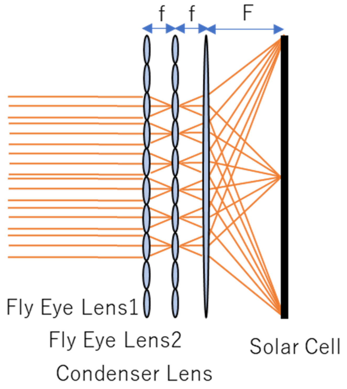
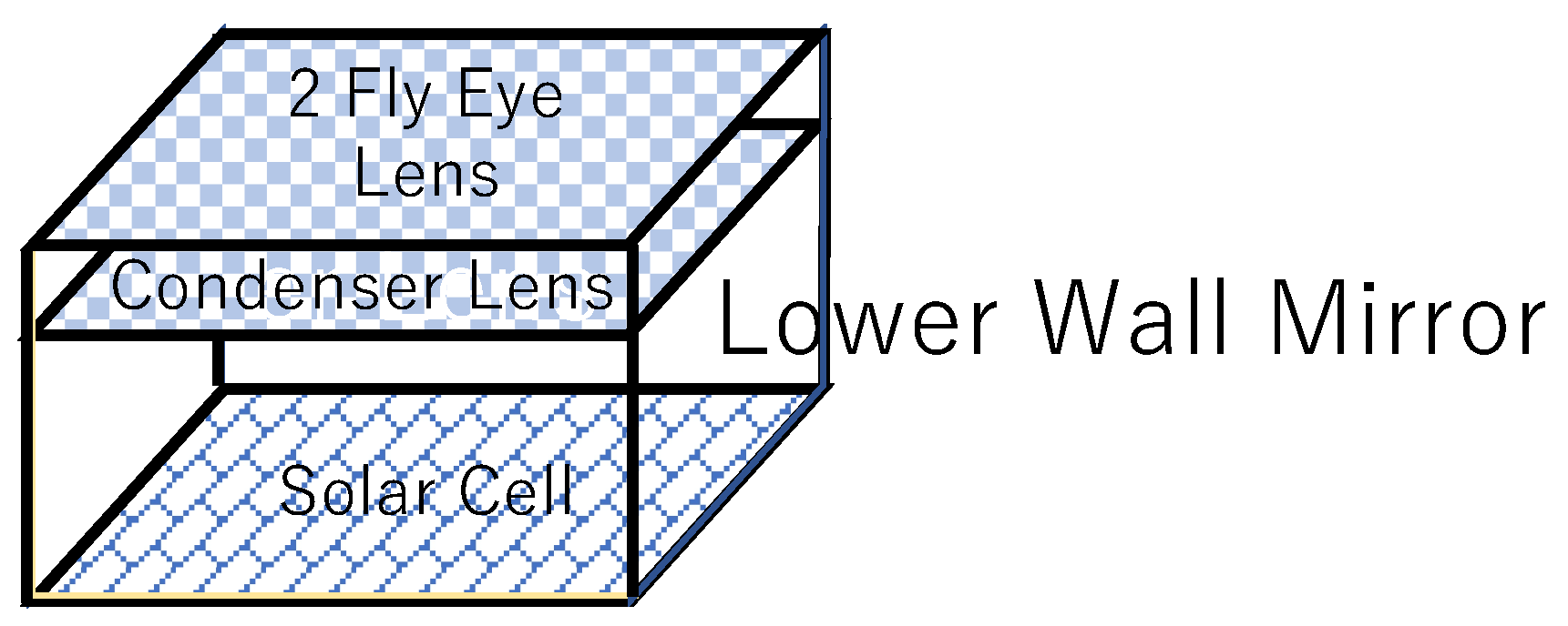
2. Fly Eye Module Model

For general simplified OWPT systems, system power transmission efficiency is described by:
η s y s t e m = η L i g h t   S o u r c e × η T r a n s m i s s i o n × η P o w e r   G e n e r a t i o n × η S o l a r   C e l l
where η L i g h t   S o u r c e and η S o l a r   C e l l are efficiency parameters specific to devices, and η T r a n s m i s s i o n is an environmental parameter. The factor, the ‘power generation ratio ( η P o w e r   G e n e r a t i o n )’ describes the effect of system level efficiency, including optics such as beam alignment and shaping. It is calculated from the light beam power contributing to power generation in the solar cell, which is a portion of the power transferred from the incident beam. This factor is studied by Tang et al. [27] for a typical solar cell module with a series of connected solar cells without any bypass diodes. Power generation ratio is the product of two factors. The first one (factor A) accounts for the portion of light beam that irradiates the solar cell module, which is the ratio of the area of incident beam overlapping with solar cell to the total area of incident beam. The second one (factor B) accounts for nonlinear characteristics of the solar cell array caused by shadowing of the solar cell module. This factor will depend on detailed internal configuration of the array such as number, shape and orientation of each solar cell element. Improving the efficiency does not mean that the light beam is simply incident on the solar cell. To maximize power generation ratio and achieve high efficiency, one needs to adjust the shape of the incident beam with that of the array to avoid non-irradiated area and power loss due to shape mismatch between the beam and the array. Moreover, power generation efficiency in the solar cell depends on irradiated power density. To maximize the power generation ratio, homogeneity of the irradiated beam is necessary. To build a robust OWPT accommodating such requirements is one of the major tasks in its development.
Figure 1 shows a basic configuration of the solar cell array with fly eye lens. As examples of lens parameters for assumed configuration, focal length of each element lens is f = 20 mm, and its shape is square with d = 10 mm side length. Focal length of the condenser lens is F = 200 mm, and it is square shape with D = 100 mm side length. A 10 × 10 (100) element lens composes one fly eye lens. If the incident beam size is equal to or larger than the element lens, it is still smaller than the size of the solar cell array; each image of the element lens is projected onto the focal plane of the condenser lens with F d / f size. It should be noted that this is independent of incident beam size. Since the size of the solar cell array in Figure 1 is matched with the size of F d / f , the whole area of the array is irradiated by the incident beam without any non-irradiated area.
The factor B of the power generation ratio will be a complex function of the internal configuration of the solar cell array. However, since the whole area of the array is irradiated by the incident beam in the Figure 1 module, and, therefore, the factor B is always equal to one (100%) in an ideal case, there is no need for such information of the internal configuration of the array. It should be emphasized that this is a clear advantage of the fly eye module in system design. If efficiency of the solar cell depends on the factor B, there always needs to be some assumption of the internal configuration of the solar cell array in its efficiency calculation [22,26,28]. This fly eye module can avoid such assumptions, and, as a result, the efficiency calculation model becomes much simpler than the previous one without this module [22]. In the case of the operating OWPT composed of solar cells, which have different internal configurations from each other, there would be a possibility that efficiencies of different internal solar cell configurations are different. This module absorbs such internal configuration difference and would produce uniform efficiency.
The remaining issue is maximizing the factor A. Focus adjustment, beam alignment and the beam confinement mechanism of this module are studied in the following sections.

3. Cooperative OWPT with the Fly Eye Module

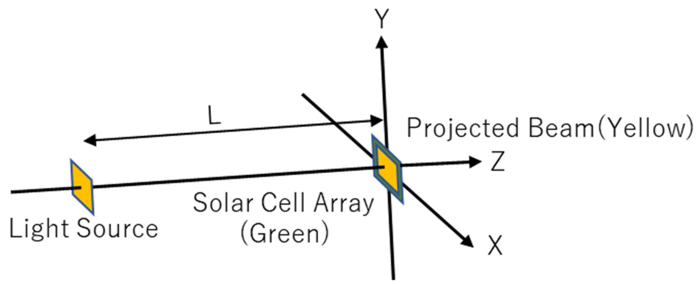
3.1. Geometrical, Optical Configuration of the Analysis

Figure 2 shows the geometrical configuration of this analysis, assuming attitude of the solar cell array is always dynamically controlled to face with the transmitter (cooperative OWPT). In this study, size of the light source is 5 mm × 5 mm, beam divergence is 0.8 degree (half angle) and power profile is top hat. Transmitter optics include a simple beam expander, focal length of the two lenses are 150 mm and −30 mm, and nominal separation between the two lenses is 120 mm. The beam expander is defocused for the distance range to the module (L) to adjust the beam size at the entrance of the fly eye module. The size of the solar cell array is 100 mm × 100 mm, and beam size is adjusted to the smaller size of the array by controlling the focus of the beam expander. In the following investigation in this report, the beam size is considered to be 1/2 (one-half) of the size of the array. Even though each size in the system in this report is fixed for numerical analysis purposes, the result is readily scalable to the other sizes.

3.2. Power Generation Ratio, Homogenization by Fly Eye Module

The fly eye module homogenizes power density and projects the beam over the whole area of the solar cell array. If the beam size is smaller than the size of the array, the whole power of the irradiated beam will be confined within the fly eye module, and a high power generation ratio is expected. An oversized beam causes degradation of the efficiency due to leakage of the light beam from the receiver module. As the array always faces with the transmitter in cooperative OWPT, the power generation ratio is 100% if the beam expander is always defocused appropriately for the range to the array. In the case of a moving array, this requires real-time defocusing adjustment for the beam expander based on range information to the array. To relax this strong requirement, defocusing for a fixed range is investigated in this study. Figure 3 shows range dependence of size of several beams, whose size at fly eye module entrance is adjusted to be one-half of the size of the array at 1 m, 5 m, 10 m, 20 m, 30 m, 40 m, 80 m and 100 m. If defocusing is adjusted for a fixed range longer than 30 m, e.g., 40 m, 80 m or 100 m, the size of the beam is always less than the size of the array (100 mm) within 100 m. Otherwise, the beam size becomes larger than that of the array (>100 mm) at some range. From here, defocusing the beam expander is called ‘focus adjustment’ or ‘focus optimization’, and distance range from the transmitter to the solar cell array is called ‘L’.
Assume each focus of beams is adjusted such that the size of the beams at 40 m, 80 m and 100 m are to be one-half of the size of the array. The size of such beams do not exceed that of the array within 100 m range to it. To see the homogenization effect for these beams by the fly eye module, range dependence of power density of the incident beam is calculated in Figure 4 and Figure 5, both at the fly eye module entrance and at the solar cell array (SC).
In the calculation, the power of each beam is assumed to be 1 (one) watt and size of the fly eye entrance and solar cell array are both 100 mm × 100 mm. For the calculation, 100 × 100 grid points are defined in each fly eye element lens. Power densities are calculated on each 100 × 100 grid points of each element lens at the module entrance and projected onto 100 × 100 grid points at the solar cell array.
Power density at (I, J) grid point (I, J: 1 to 100) of the solar cell array is given by:
I S C ( I ,   J ) = a ,   b = 1 10 I a , b ( I ,   J )
where I S C ( I ,   J ) is power density at (I, J) grid point of solar cell array and I a , b ( I ,   J ) is power density at (I, J) grid point of (a, b) element lens. Indices a, b are from 1 to 10, because a 10 × 10 element lens composes one fly eye lens.
Power density varies with both focus adjustment range (40 m, 80 m, 100 m) and range to the array (1 m, 5 m, 10 m, 50 m, 100 m). Figure 6 and Figure 7 show homogeneity at the solar cell array. In these plots, homogeneities are defined as the ratio of minimum power density to mean power density over the array in Figure 6 and the ratio of minimum power density to maximum power density in Figure 7.
Even though there are some inhomogeneities of power density at the array in both plots, it should be noted that rigorous ‘homogeneity’ is not pursued in this study but ‘irradiation over whole area of the array,’ and ‘beam power confinement inside the fly eye module’ are prioritized. In fact, such inhomogeneities are less than a factor of two in Figure 6 and Figure 7 and are acceptable for practical purpose of OWPT.
Figure 8 shows the power generation ratio for each adjustment. As shown in Figure 3, if the focus is adjusted at more than 30 m, the beam size is less than 100 mm within 100 m range. Thus, the power generation ratio is 100% from 0 m to 100 m for adjustment of 40, 80 and 100 m in Figure 8. This means that if the beam size is less than the array size (100 mm), the power generation ratio is maintained at 100%. Even the focus of the beam expander is fixed for some range; the power generation ratio can be stably efficient even if L varies. This example shows that focus adjustment once at more than 30 m is enough, and it can be fixed for stabilizing the power generation ratio from 0 m to 100 m.

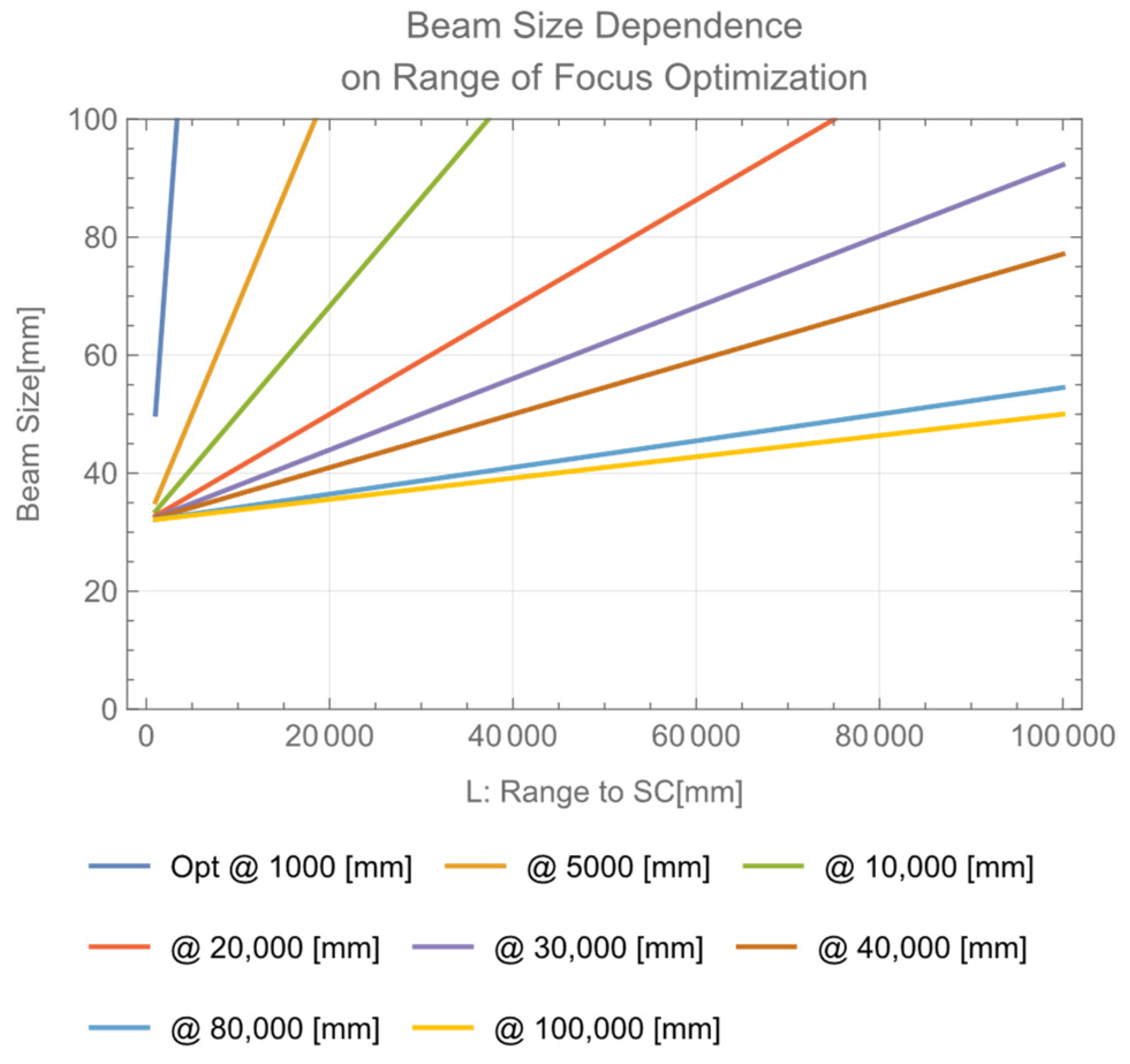
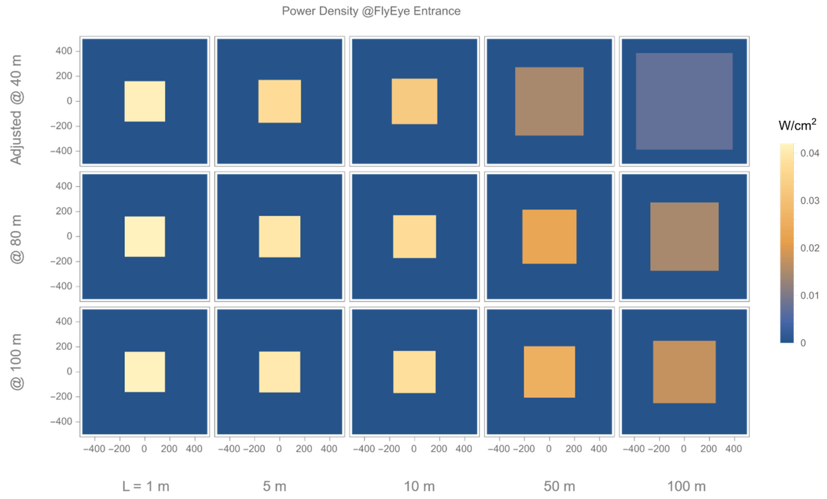
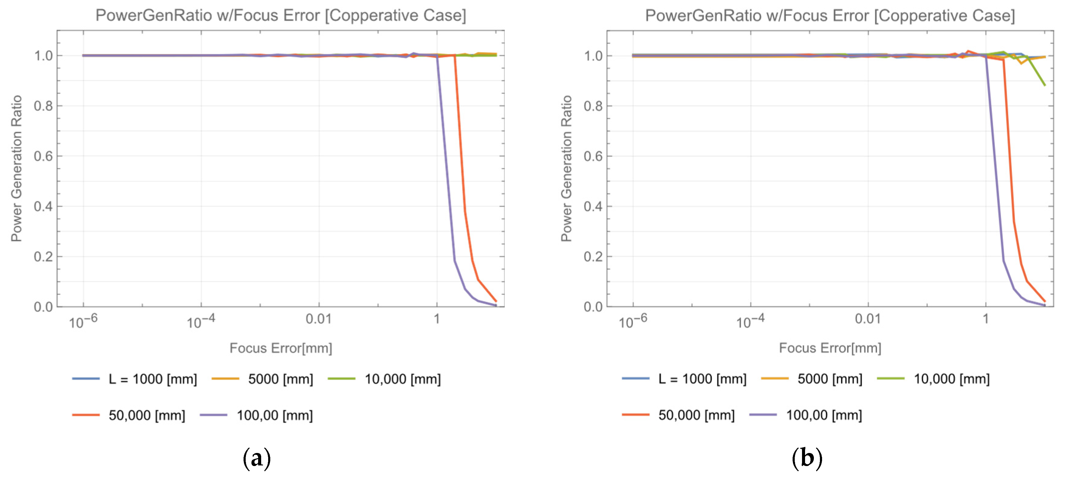
4. Requirement for Focus Adjustment of Transmitter Beam Expander

The requirement for focus adjustment is investigated. In the case that focus is optimized for each L, about 1 mm focus error is allowable (Figure 9a). When focus is fixed at some range, e.g., 100 m in Figure 9b, similarly 1 mm focus error is allowed in this case. The requirements for this focus adjustment are greatly relaxed compared to when the fly eye is not used [22].

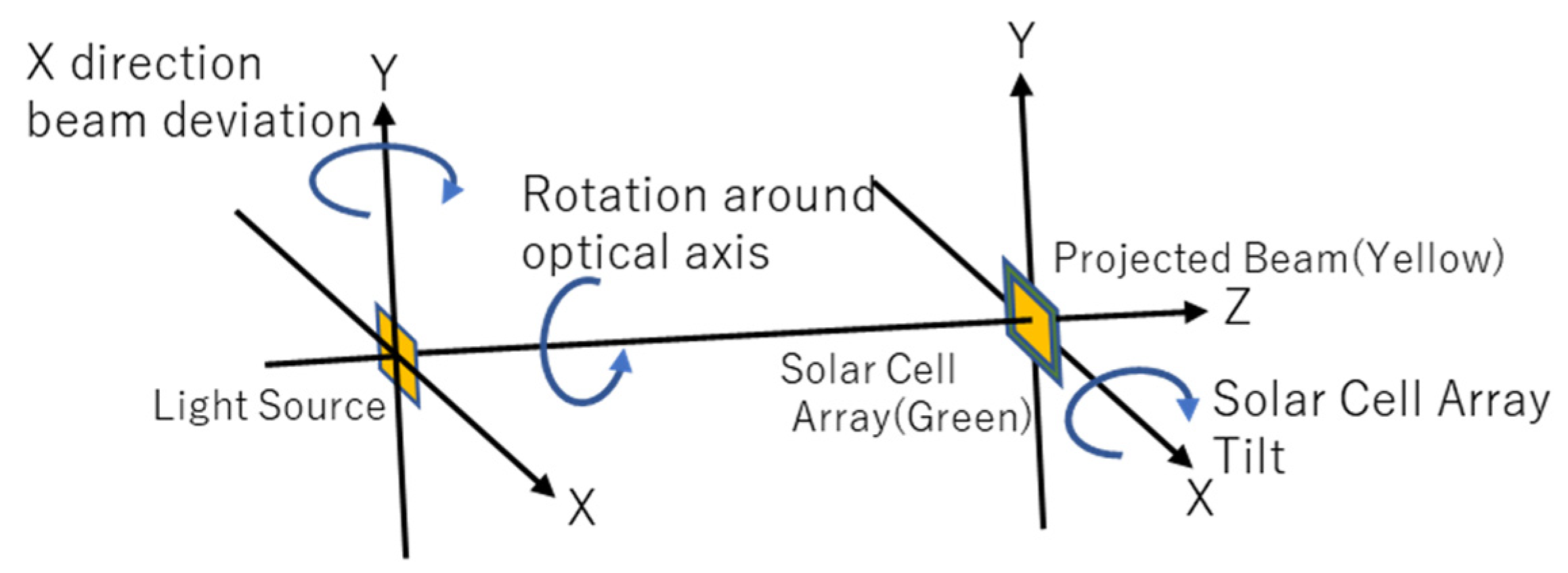
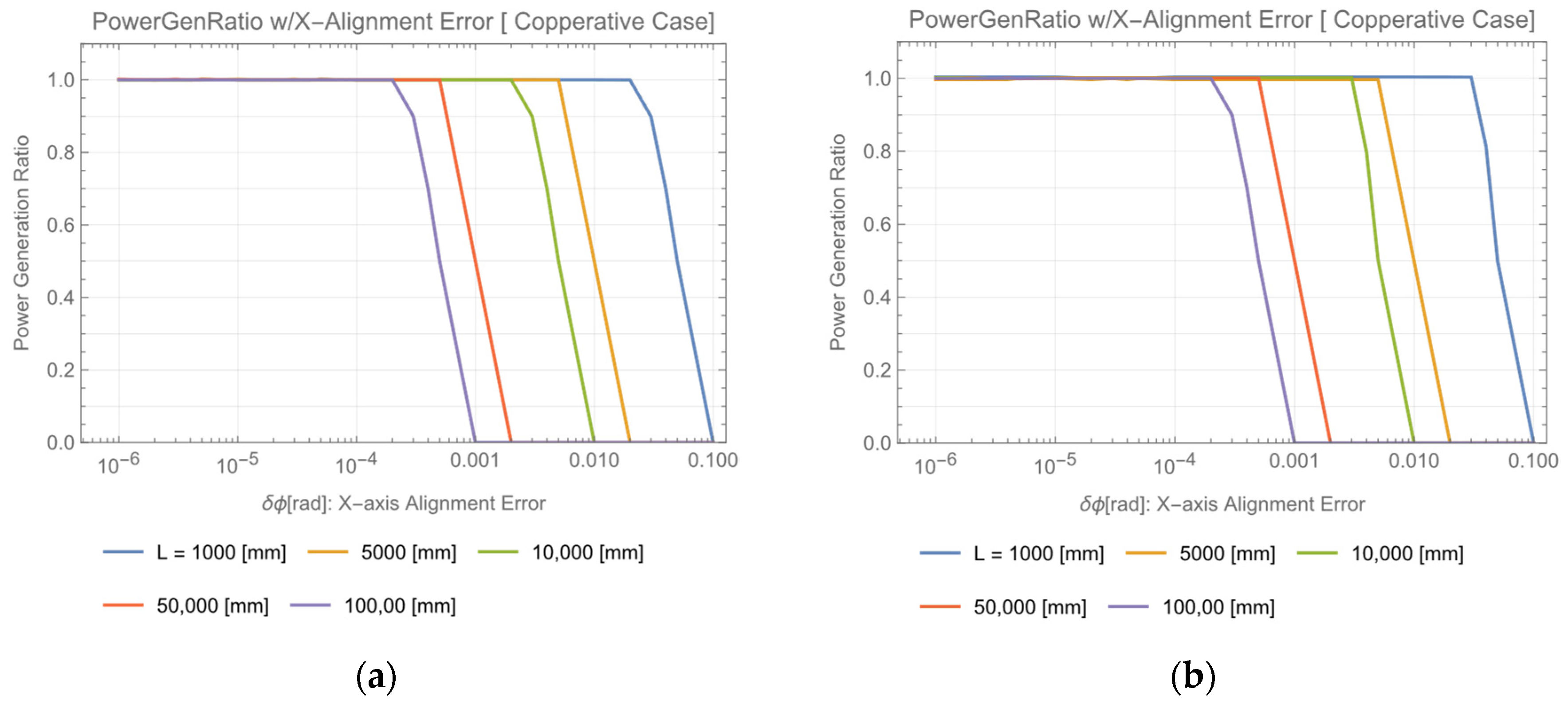
5. Requirement for Beam Alignment

5.1. X(Y) Direction Beam Alignment

In cooperative OWPT, not only focus adjustment, but also alignment of position and attitude of the solar cell array relative to the transmitter is necessary. Degree of freedom (DoF) of beam alignment is two for X, Y direction deviation, two for rotation around X, Y axes, and one for rotation around beam propagation direction. Therefore, there are five DoFs in total. Since the X, Y directions are identical, the number of independent requirements for beam alignment reduces to three. In this study, these DoFs are assigned to deviation in X(Y) direction, tilt of solar cell array and rotation around the optical axis (beam direction) (Figure 10).
The initial state is that the beam is exactly directed to the center of the solar cell array, and its shape is matched with that of the array. Then, the light source is deviated in X direction by rotating around Y axis and the power generation ratio is calculated. In Figure 11a, like Figure 9a, focus is optimized for each L. In Figure 11b, like Figure 9b, focus is optimized at 100 m and fixed. Similar results are obtained from both cases. L dependent requirements are determined at 80% of the power generation ratio, e.g., 34 mrad at L = 1 m, 3.4 mrad at L = 10 m, 0.32 mrad at L = 100 m. As X, Y direction are identical, requirement for both X, Y direction are the same. In this study, the beam size was set to 1/2 (half) of the size of the fly eye lens array, as defined in the beginning of the Section 3. Changing this size slightly changes the characteristics in Figure 11.

5.2. Rotational Alignment around Beam Direction

The requirement for rotational alignment around the optical axis is investigated. In Figure 12a, focus is optimized for each L. In Figure 12b, focus is optimized at 100 m and fixed. Similar results are obtained from both cases. Since the beam size is less than the size of the array for every rotation angle and for every L < 100 m, the power generation ratio is stably 100% for any rotation angle and for L. As defined in the beginning of Section 3, in this study, the beam size was set to 1/2 (half) of the size of the array. When this beam size approaches the array size, the efficiency in Figure 12 degrades because part of the beam leaks out of the lens array, especially under a rotation angle of close to 45 degrees. This means that maintaining a sufficiently small beam size is advantageous for the proposed configuration.

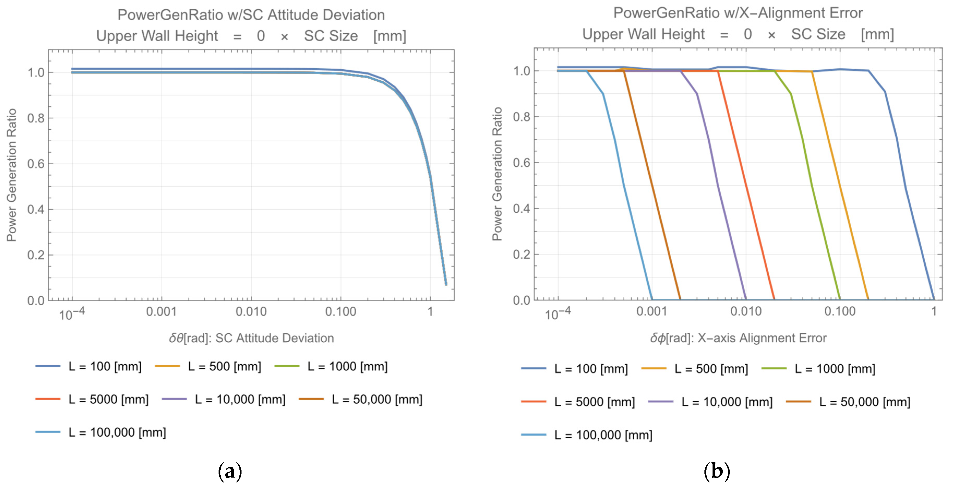
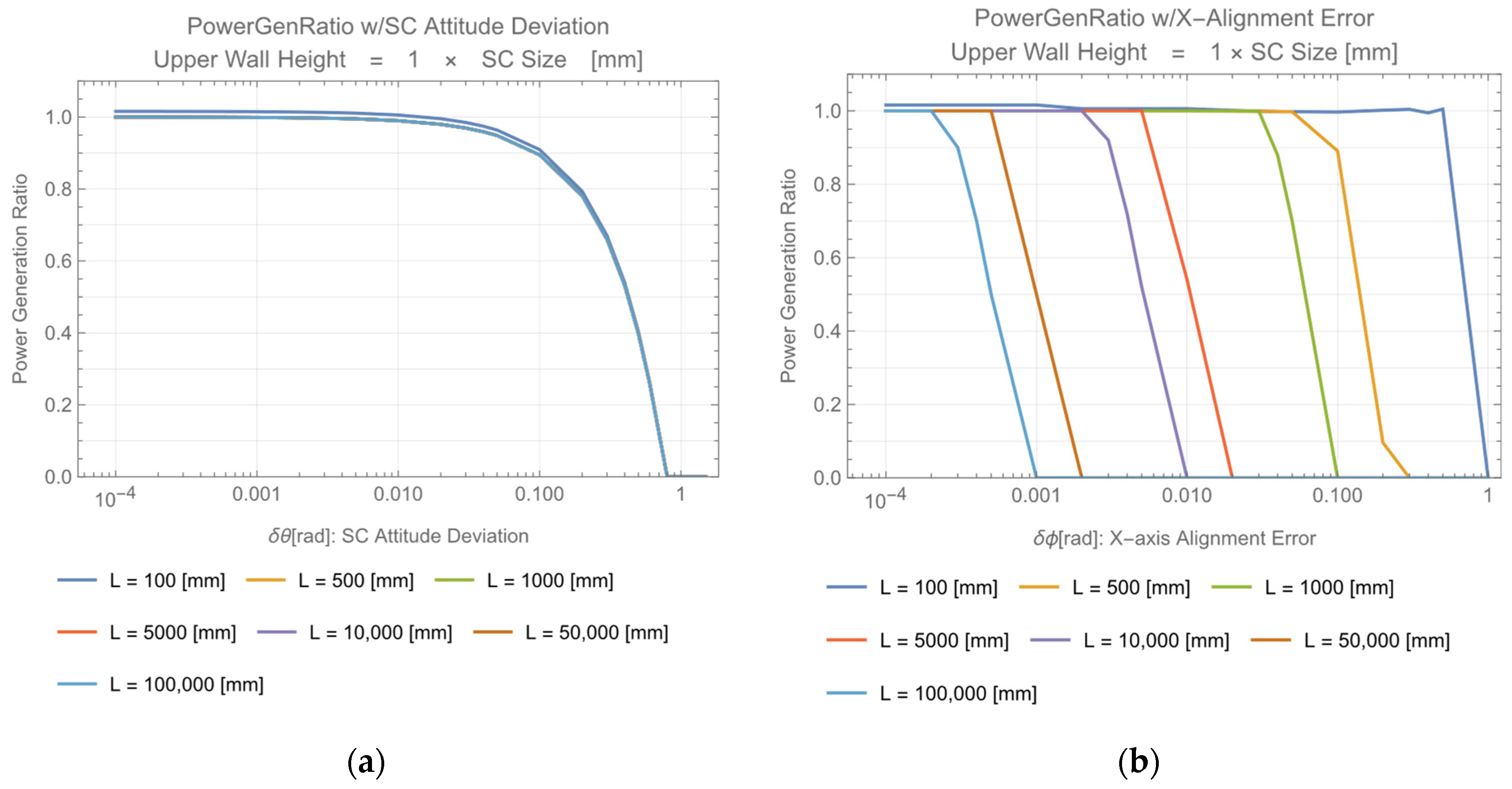
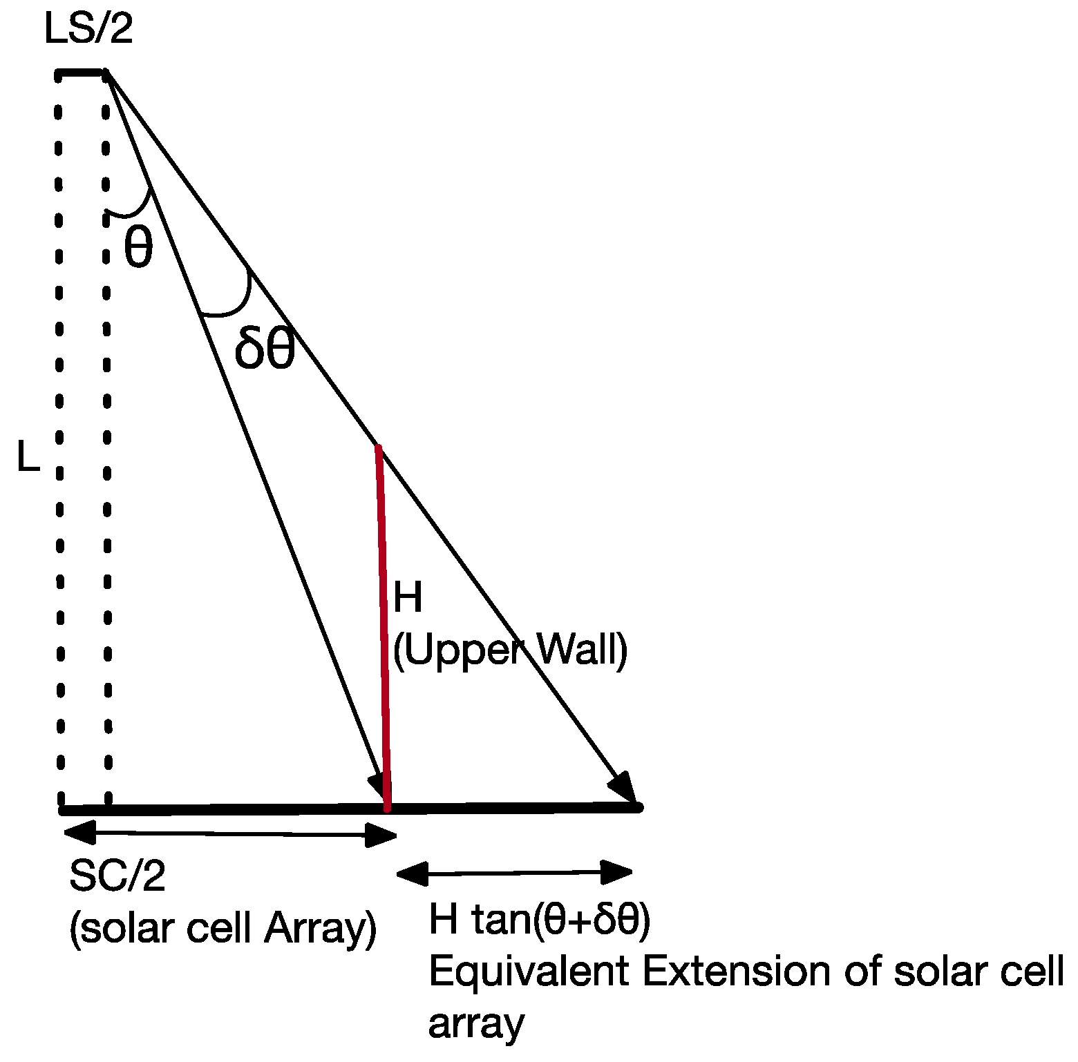
6. Requirement for Tilt of Solar Cell and Beam Energy Confinement in the Fly Eye Module

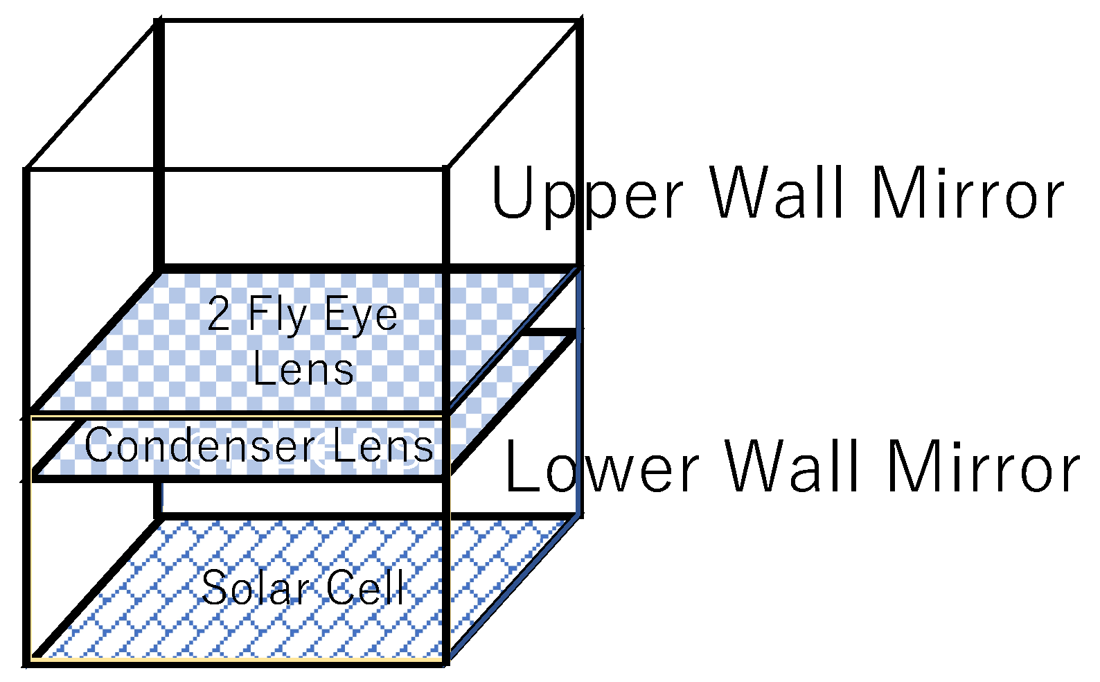
6.1. Upper Wall Mirror, Lower Wall Mirror Configurations

When the solar cell array is tilted, the incident angle of the beam to the array changes. It should be accounted that the projected beam on the array is not only moved to the adjacent area but also some portion of the beam is vignetted. To avoid these problems, Katsuta et al. suggested an initial concept of surrounding reflective side panels between the fly eye lens and solar cell array [25] (Lower Wall Mirror in Figure 13).
There is another configuration that has reflective side panels above fly eye lens (Upper Wall Mirror in Figure 10). A similar idea is found in the literature [28].
By using such surrounding mirrors, as shown in Figure 13 and Figure 14, spilled beam energy from the side of the module is reflected, and beam energy is confined in the module as a result. There are some studies of solar cell device level light trapping structures to avoid beam energy loss [29,30]. It should be emphasized that these module level beam confinement structures, such as Figure 13 and Figure 14 studied here, avoid spilled energy from the module and are expected to relax requirements for X(Y) direction beam deviation. The beam energy is efficiently transferred to the array by these confinement configurations and trapped there if there are any device level trapping mechanisms there. In this study, the beam confinement concept is numerically analyzed in terms of power generation ratio, and requirements are derived for beam alignment in Figure 13 and Figure 14 configurations. In this analysis, the reflectivity of the mirrors is assumed to be 100% for any reflection angle.

6.2. Beam Acceptance Angle and Beam Confinement Effect in Fly Eye Module with Uppwe/Lower Wall Mirror

In Figure 13, the configuration with the lower wall mirror only, the power generation ratio is calculated for the tilt angle relative to the beam (incident angle of the beam) (Figure 15a) and for the X(Y) deviation of the beam (Figure 15b).
In the configuration of Figure 14, where upper wall height = SC (solar cell array size), the power generation ratio is calculated for solar cell array attitude deviation (Figure 16a) and X(Y) axis angle deviation (Figure 16b).
Let H be the height of the upper wall mirror and θ be the X(Y) axis angle deviation limit. Assume one deviates the beam in the X(Y) direction, and the upper wall mirror reflects the deviated beam onto the fly eye module (solar cell array). This effect is equivalently expressed by extension of the size of the fly eye module by H   t a n ( θ + δ θ ) , as shown in Figure 17.
The order of θ and δθ is O ( S C / 2 L ) . In the case H = SC = 100 mm, L = 1000 mm; this is the equivalent to extend the module size about 10%. The upper wall mirror’s beam confinement effect becomes larger when L and SC are comparable and negligible when LSC. This is observed in the right figures of Figure 15 and Figure 16.
Each requirement depends on L. Table 1 shows excerpts from Figure 15 and Figure 16. Each requirement is defined at the point power generation ratio equals 80%. SC means the size of the solar cell array (100 mm). These system level requirements are much more relaxed from requirements without the fly eye module in the former study [22].
When the beam enters the fly eye lens with a larger incident angle than its critical angle, the projected beam image is transferred to the adjacent area. Its critical angle can be expressed as t a n θ c = d / 2 f , where d is the size of the element lens and f is its focal length. In Figure 1 configuration, the critical angle is 245 mrad (14.3 degrees), numerically. Without the lower-wall mirror, this results in a zero power generation ratio. For the module with neither upper nor lower wall mirrors (Wall-Less configuration), the power generation ratio changes the same as the lower wall mirror configuration for incident angle θ < θ c and becomes zero for θ θ c . This leads to a requirement of within 245 mrad incident angle for this case. Regarding the X(Y) direction beam deviation, requirements are the same as the Lower Wall Mirror configuration, since both configurations do not have the upper wall mirror. With the lower-wall reflective mirror (Lower-Wall Mirror configuration), the power generation ratio is maintained at high efficiency, and critical angle θ c is no longer a restriction for the incident angle of the beam. On the other hand, assuming the beam enters solar cell array of cross section S (= SC × SC) with incident angle θ , its apparent area of solar cell array becomes S c o s θ when observed from the incident beam. If beam size exceeds S c o s θ , power generation degrades. This is the only restriction for the beam incident angle in terms of the power generation ratio in the Lower-Wall Mirror configuration. Beam size control in the light source side will be effective for this situation.
In the case of the Two-Wall Mirror configuration, the incident angle requirement is stronger than the lower-wall mirror case. This is due to vignetting of the incident beam by the upper wall in this configuration, since the effective area of the solar cell array is reduced to S ( c o s θ H / S C   s i n θ ) . If the beam size is sufficiently large, such vignetting is compensated by the equivalent extension of the solar cell array’s area, such as in the case of the X(Y) direction (Figure 18). In this case, since the beam size at the solar cell is 1/2 (half) of its size, this does not occur.
On the other hand, the X(Y) beam deviation requirement is more relaxed than the lower-wall mirror configuration. This is due to the beam confinement effect by the upper wall. In the case that L and SC are comparable, the precise beam alignment for tilt of the solar cell array (the fly eye module) is almost unnecessary.

7. Discussion

The fly eye module in Figure 1 with both upper and lower wall mirrors suffers an increase in its size. In Figure 1, the size of the fly eye lens is 100 mm × 100 mm, its element lens is 10 mm × 10 mm with 20 mm focal length, and the size of the condenser lens is 100 mm × 100 mm with 200 mm focal length. The size of the whole module is at least 100 mm × 100 mm × 200 mm. When the upper wall mirror is included, the module size depends on the upper wall height. If the upper wall height is the same as the solar array, the module size increases to 100 mm × 100 mm × 300 mm. In a module such as Figure 1, the problem would be size and focal length of each lens and height of the upper wall mirror to irradiate the whole area of the solar cell array and to confine the beam power within the module. The size of the solar array is 100 mm × 100 mm, which assumes that twelve solar cell elements are series connected in the array, and the fly eye module size increases or decreases proportional to the size of this solar cell element. Even though such a module as Figure 1 would be acceptable by some applications, miniaturization is always favorable. If a miniaturized solar cell array could be developed, miniaturization of the fly eye module would be also feasible. Even though a miniature module can generate small amounts of electrical current, a necessary number of parallel connected modules would both generate enough current and achieve compactification of the whole OWPT system. Development effort towards such miniaturization is proposed and expected.

8. Conclusions

In the OWPT system, both beam alignment and shaping accuracies would affect not only alignment and shaping mechanisms, but also detection accuracy and mechanism of the SC position and attitude by light source. As shown in the former study [22], the longer the distance to the SC, the stronger these requirements are. These would make it seriously difficult to build robust and practical OWPT systems, especially when they support long range power transmission.
In this study, the system level requirement of a cooperative OWPT system is theoretically analyzed. Analysis is conducted with a module utilizing the fly eye lens surrounded by reflective walls (fly eye module). When the irradiated beam size is smaller than the solar cell array size in the fly eye module, the beam irradiates the whole solar cell array, and its power density is homogenized. In a cooperative OWPT utilizing such a module, the transmitter optics focus adjustment is only necessary in advance of operation at some range with 1 mm accuracy, and additional adjustment is no longer necessary if the size of the beam is always less than that of the array within the operational range. In addition to this, rotation adjustment around the optical axis is not necessary for the same assumption of the size between the beam and the array. The requirement for beam incident angle and beam direction deviation is relaxed by the surrounding reflective wall configuration of the module. There would be an upper wall mirror above the fly eye lens, and a lower wall mirror from the fly eye lens to the solar cell array. Comparing the two-wall mirror configuration with the lower-wall mirror configuration, the requirement for the beam incident angle is stronger and the one for beam deviation is weaker. In OWPT system design, it is a trade-off item that should be prioritized, either the incident angle or balancing both requirements.
Beam power is confined within the module and will be eventually absorbed by the solar cell for the incident beam within the acceptance angle determined by the requirements. This feature avoids degradation of power generation ratio due to beam shape mismatch and eye-safety problems due to spilled beam from the module. These advantages of the module, made clear in this study, bring progress towards building a practical and robust OWPT.

Author Contributions

Conceptualization, K.A. and T.M.; methodology, K.A. and T.M.; formal analysis, K.A.; investigation, K.A.; writing—original draft preparation, K.A.; writing—review and editing, T.M.; project administration, T.M.; funding acquisition, T.M. All authors have read and agreed to the published version of the manuscript.

Funding

This work was partially supported by the Tsurugi-Photonics Foundation (No. 20220502) for the Promotion of Photon Science and the Takahashi Foundation for Industrial and Economic Research (No. I2-003-13). In addition, part of this paper is based on the project commissioned based on the Mechanical Social Systems Foundation and Optoelectronic Industry and Technology Development Association (“Formulation of strategies for market development of optical wireless power transmission systems for small mobilities”).

Institutional Review Board Statement

Not applicable.

Informed Consent Statement

Not applicable.

Acknowledgments

We thank members in the T. Miyamoto Lab for discussion and assistance.

Conflicts of Interest

The authors declare no conflict of interest.

References

  1. Frolova, E.; Dobroskok, N.; Morozov, A. Critical Review of Wireless Electromagnetic Power Transmission Methods; Atlantis Press International B.V: Saint-Petersburg, Russia, 2022. [Google Scholar] [CrossRef]
  2. Kurooka, K.; Honda, T.; Komazawa, Y.; Warigaya, R.; Uchida, S. A 46.7% Efficient GaInP Photonic Power Converter under High-Power 638 Nm Laser Uniform Irradiation of 1.5 W/cm2. Appl. Phys. Express 2022, 15, 062003. [Google Scholar] [CrossRef]
  3. Peng, Y.S.; Yao, M.H.; Liu, Z.M.; Tu, J.L.; Cao, Q.J.; Gong, S.F.; Hu, Y.T.; Zhou, S.L. Numerical Investigation on Performance of Ultra-Thin GaAs Solar Cells Enabled with Frontal Surface Pyramid Array. J. Phys. D Appl. Phys. 2022, 55, 245105. [Google Scholar] [CrossRef]
  4. Nguyen, D.H.; Tumen-Ulzii, G.; Matsushima, T.; Adachi, C. Performance Analysis of a Perovskite-Based Thing-to-Thing Optical Wireless Power Transfer System. IEEE Photonics J. 2022, 14, 1–8. [Google Scholar] [CrossRef]
  5. Hassan, M.R. Theory of Dronized Laser Source for Next Generation of Optical Wireless Power Transmission. IEEE J. Select. Top. Quantum Electron. 2022, 28, 1–9. [Google Scholar] [CrossRef]
  6. Setiawan Putra, A.W.; Tanizawa, M.; Maruyama, T. Optical Wireless Power Transmission Using Si Photovoltaic through Air, Water, and Skin. IEEE Photon. Technol. Lett. 2019, 31, 157–160. [Google Scholar] [CrossRef]
  7. Rathod, Y.; Hughes, L. Simulating the Charging of Electric Vehicles by Laser. Procedia Comput. Sci. 2019, 155, 527–534. [Google Scholar] [CrossRef]
  8. Iyer, V.; Bayati, E.; Nandakumar, R.; Majumdar, A.; Gollakota, S. Charging a Smartphone across a Room Using Lasers. Proc. ACM Interact. Mob. Wearable Ubiquitous Technol. 2018, 1, 1–21. [Google Scholar] [CrossRef]
  9. Baraskar, A.; Yoshimura, Y.; Nagasaki, S.; Hanada, T. Space Solar Power Satellite for the Moon and Mars Mission. J. Space Saf. Eng. 2022, 9, 96–105. [Google Scholar] [CrossRef]
  10. Lee, N.; Blanchard, J.T.; Kawamura, K.; Weldon, B.; Ying, M.; Young, S.A.; Close, S. Supporting Uranus Exploration with Deployable ChipSat Probes. In Proceedings of the AIAA SCITECH 2022 Forum, San Diego, CA, USA & Virtual, 3–7 January 2022; American Institute of Aeronautics and Astronautics: Reston, VA, USA, 2022. [Google Scholar] [CrossRef]
  11. Landis, G.A. Laser Power Beaming for Lunar Polar Exploration. In Proceedings of the AIAA Propulsion and Energy 2020 Forum, Virtual Event, 24–28 August 2020; American Institute of Aeronautics and Astronautics: Reston, VA, USA, 2020. [Google Scholar] [CrossRef]
  12. Atul, A. A Study on Space-Based Solar Power System. IOSR-JESTFT 2015, 1, 1–3. [Google Scholar]
  13. Mori, M.; Kagawa, H.; Saito, Y. Summary of Studies on Space Solar Power Systems of Japan Aerospace Exploration Agency (JAXA). Acta Astronaut. 2006, 59, 132–138. [Google Scholar] [CrossRef]
  14. Wang, Z.; Zhang, Y.; He, X.; Luo, B.; Mai, R. Research and Application of Capacitive Power Transfer System: A Review. Electronics 2022, 11, 1158. [Google Scholar] [CrossRef]
  15. Setiawan Putra, A.W.; Kato, H.; Maruyama, T. Infrared LED Marker for Target Recognition in Indoor and Outdoor Applications of Optical Wireless Power Transmission System. Jpn. J. Appl. Phys. 2020, 59, SOOD06. [Google Scholar] [CrossRef]
  16. Takeda, K.; Kawashima, N. 1.2 km Laser Energy Transmission for the Lunar Rover Model to Explore the Ice on the Moon. Space Technol. Jpn. Jpn. Soc. Aeronaut. Space Sci. 2004, 3, 45–48. [Google Scholar] [CrossRef]
  17. Takeda, K.; Kawashima, N. 100 m Laser Energy Transportation Experiment to a Model Rover to Explore the Ice on the Moon. J. Jpn. Soc. Aeronaut. Space Sci. 2003, 51, 393–396. [Google Scholar] [CrossRef]
  18. Mukherjee, J.; Wulfken, W.; Hartje, H.; Steinsiek, F.; Perren, M.; Sweeney, S.J. Demonstration of Eye-Safe (1550 Nm) Terrestrial Laser Power Beaming at 30 m and Subsequent Conversion into Electrical Power Using Dedicated Photovoltaics. In Proceedings of the 2013 IEEE 39th Photovoltaic Specialists Conference (PVSC), Tampa, FL, USA, 16–21 June 2013; pp. 1074–1076. [Google Scholar] [CrossRef]
  19. PowerLight Technologies. Available online: https://powerlighttech.com/ (accessed on 23 May 2022).
  20. The Wireless Power Company. Wi-Charge. Available online: https://www.wi-charge.com (accessed on 9 May 2022).
  21. Kim, S.-M. Optical Beamforming for Communication and Power Transmission. SPIE Newsroom, 6 February 2014. [Google Scholar] [CrossRef] [Green Version]
  22. Asaba, K.; Miyamoto, T. System Level Requirement Analysis of Beam Alignment and Shaping for Optical Wireless Power Transmission System by Semi–Empirical Simulation. Photonics 2022, 9, 452. [Google Scholar] [CrossRef]
  23. Kakeya, H.; Sawada, S.; Ueda, Y.; Kurokawa, T. Integral Volumetric Imaging with Dual Layer Fly-Eye Lenses. Opt. Express 2012, 20, 1963. [Google Scholar] [CrossRef]
  24. Mori, N. Design of Projection System for Optical Wireless Power Transmission Using Multiple Laser Light Sources, Fly-Eye Lenses, and Zoom Lens. In Proceedings of the 1st Optical Wireless and Fiber Power Transmission Conference (OWPT2019), Yokohama, Japan, 23–25 April 2019; OWPT-3-02. [Google Scholar]
  25. Katsuta, Y.; Miyamoto, T. Design, Simulation and Characterization of Fly-Eye Lens System for Optical Wireless Power Transmission. Jpn. J. Appl. Phys. 2019, 58, SJJE02. [Google Scholar] [CrossRef]
  26. Tai, Y.; Miyamoto, T. Experimental Configuration of Fly-eye Lens Based Underwater Optical Wireless Power Transmission. In Proceedings of the 4th Optical Wireless and Fiber Power Transmission Conference (OWPT2022), OWPT-3-02, Online, Japan, 18–21 April 2022. [Google Scholar]
  27. Tang, J.; Matsunaga, K.; Miyamoto, T. Numerical Analysis of Power Generation Characteristics in Beam Irradiation Control of Indoor OWPT System. Opt. Rev. 2020, 27, 170–176. [Google Scholar] [CrossRef]
  28. Wagner, L.; Bett, A.W.; Helmers, H. On the alignment tolerance of photovoltaic laser power converters. Optik 2017, 131, 287–291. [Google Scholar] [CrossRef]
  29. Alsaigh, R.E.; Bauer, R.; Lavery, M.P.J. Multi-Element Lenslet Array for Efficient Solar Collection at Extreme Angles of Incidence. Sci. Rep. 2020, 10, 8741. [Google Scholar] [CrossRef]
  30. Takeda, Y.; Iizuka, H.; Mizuno, S.; Hasegawa, K.; Ichikawa, T.; Ito, H.; Kajino, T.; Ichiki, A.; Motohiro, T. Silicon Photovoltaic Cells Coupled with Solar-Pumped Fiber Lasers Emitting at 1064 nm. J. Appl. Phys. 2014, 116, 014501. [Google Scholar] [CrossRef]
Figure 1. Solar Cell Array with Fly Eye Lens.
Photonics 09 00995 g001
Figure 2. Configuration of this analysis.
Photonics 09 00995 g002
Figure 3. Beam size with focus adjustment at fixed range.
Photonics 09 00995 g003
Figure 4. Power density of the incident beam at fly eye module’s entrance.
Photonics 09 00995 g004
Figure 5. Power density of the incident beam at solar cell array (SC).
Photonics 09 00995 g005
Figure 6. Homogeneity (Min Power Density/Mean Power Density).
Photonics 09 00995 g006
Figure 7. Homogeneity (Min Power Density/Max Power Density).
Photonics 09 00995 g007
Figure 8. Range dependence of power generation ratio for various focus adjustment range.
Photonics 09 00995 g008
Figure 9. Power Generation Ratio Dependence on Focus Adjustment: (a) Focus Optimized at Each L; (b) Focus Optimized at 100 m.
Photonics 09 00995 g009
Figure 10. Beam alignment in cooperative OWPT system.
Photonics 09 00995 g010
Figure 11. Power Generation Ratio Dependence on X(Y) Direction Deviation: (a) Focus Optimized at Each L; (b) Focus Optimized at 100 m.
Photonics 09 00995 g011
Figure 12. Power Generation Ratio Dependence on Rotation around Optical Axis: (a) Focus Optimized at Each L; (b) Focus Optimized at 100 m.
Photonics 09 00995 g012
Figure 13. Fly Eye Module with Lower Wall Mirror.
Photonics 09 00995 g013
Figure 14. Fly Eye Module with Upper Wall Mirror and Lower Wall Mirror.
Photonics 09 00995 g014
Figure 15. Beam Energy Confinement by Lower Wall Mirror: (a) power generation ratio calculation for the tilt angle relative to the beam; (b) for the X(Y) deviation of the beam.
Photonics 09 00995 g015
Figure 16. Beam Energy Confinement by Upper and Lower Wall Mirror (Upper Wall Height = SC): (a) power generation ratio calculation for the tilt angle relative to the beam; (b) for the X(Y) deviation of the beam.
Photonics 09 00995 g016
Figure 17. Equivalent extension of the fly eye module size.
Photonics 09 00995 g017
Figure 18. Beam tilt in two-wall mirror configuration.
Photonics 09 00995 g018
Table 1. Requirement for Beam Incident Angle and Deviation in X(Y) Direction with Upper and Lower Wall Mirror Configuration.
ConfigurationUpper Wall HeightRequirement for Incident AngleRequirement for X(Y) Deviation
Wall-Less
(with neither lower wall nor upper wall mirror
0245 mrad340 mrad (L = 0.1 m)
34 mrad (L = 1 m)
3.4 mrad (L = 10 m)
0.32 mrad (L = 100 m)
Lower-Wall Mirror
(lower mirror only)
0499 mrad340 mrad (L = 0.1 m)
34 mrad (L = 1 m)
3.4 mrad (L = 10 m)
0.32 mrad (L = 100 m)
Two-Wall Mirror
(both upper wall and lower wall)
SC180 mrad606 mrad (L = 0.1 m)
117 mrad (L = 1 m)
4.2 mrad (L = 10 m)
0.36 mrad (L = 100 m)
Publisher’s Note: MDPI stays neutral with regard to jurisdictional claims in published maps and institutional affiliations.

