Article

Adaptive Particle Swarm Optimization for Automatic Design of Common Aperture Optical System

1
Changchun Institute of Optics, Fine Mechanics and Physics, Chinese Academy of Sciences, Changchun 130033, China
2
College of Daheng, University of Chinese Academy of Sciences, Beijing 100049, China
3
School of Remote Sensing and Information Engineering, Wuhan University, Wuhan 430072, China
*
Author to whom correspondence should be addressed.
Photonics 2022, 9(11), 807; https://doi.org/10.3390/photonics9110807
Submission received: 29 August 2022 / Revised: 8 October 2022 / Accepted: 17 October 2022 / Published: 27 October 2022

Abstract

:
This paper presents an optimal design method to solve the initial optical parameters, which is used for the common-aperture design including transmission and reflection system. On the basis of the particle swarm optimization algorithm, the self-adaptive weight and multi-level screening principle are introduced, which effectively improves the local and global searching ability in the non-linear space. Utilizing the third-order aberration and achromatic theories, the optimal initial structural parameters satisfying the objective function can be quickly calculated. We propose a common-aperture architecture and an illustrative optical design to demonstrate the concept. The system has the ability of field of view segmentation and optical path segmentation, and realizes the three-dimensional compact optical system layout. Simulations of ray tracing acquisition and imaging performances demonstrate the potential of adaptive particle swarm optimization algorithms for flexibility and simplicity in common-aperture imaging design.

1. Introduction

Optical imaging is developing towards high spatial resolution and multi-dimensional detailed imaging (multi-spectrum, multi-polarization, day and night observation), which urges the aperture and focal length of the optical system to increase constantly. As the core part of the space camera, the optical system is limited by the number of detector pixels. The traditional single optical system cannot meet the basic detection requirements, which promotes the development of optical cameras towards multi-source imaging [1,2,3,4]. Researchers found that common-aperture imaging can solve this problem well. Mico and others took the lead in using the interference method to preliminarily verify the feasibility of common-aperture imaging [5]. The concept of common aperture imaging has been put forward, which has become a research hotspot in the field of optical imaging design. For the space imaging payload, the common aperture optical design method can integrate the light paths of different wave bands and compress the imaging system volume. At present, the traditional common aperture imaging architecture consists of three parts: front optical path, light splitting element, and independent rear optical path. Among them, the realization of the pre-optical path includes Cassegrain type, off-axis three-mirror type, or refraction and transmission lens group. The light splitting elements include prisms, dichroic mirrors, etc. The rear optical system is generally composed of multiple lenses plus detectors responding to different wave bands. In the choice of the front optical system, Cassegrain type has the advantages of a large aperture and no influence of chromatic aberration compared with refractive and transmissive lens group, which is widely used in the field of space imaging [6,7,8,9,10,11]. Therefore, the common aperture imaging system may contain multiple optical initial structures, and many solutions of unknown optical parameters are introduced, that is, multi-objective solutions. On this basis, we need an optical automatic optimal design algorithm that can quickly solve the initial structure of the system. Automatic optimization design algorithms are mostly the process of simplifying non-linear problems into linear problems, and then carrying out iterative operations [12,13,14,15], such as the least square method, genetic algorithm, etc. Unfortunately, the final result of the computer operation is often the optimal solution given the initial structure, which has great limitations. The “heredity” and “mutation” of the genetic algorithm have the scalability of biological evolution. In the process of global search, the local optimal solution is often obtained, and it is easy to fall into the dilemma of a large amount of calculation, low efficiency, and difficulty in selecting the initial structure. J. Kenned and R. C. Eberhart first put forward the particle swarm optimization algorithm (PSO) [16], which is widely used in the optimization of non-linear problems due to its efficient large-scale operations and the advantages of fast integration of non-gradient information. In the latest article on PSO [17,18], Guo et al. added the least squares method to the PSO algorithm, which improved the selection speed of the best glass pair in the transmission system. Chen et al. used PSO to solve the initial parameters of the transmission common-aperture optical system, but the proposed algorithm is difficult to apply to the reflective system.
On the basis of the above analysis, there are three aspects to be considered in realizing the optical automatic design. First of all, how to characterize aberration and chromatic aberration as variables, the relevant formulas are non-linear equations, so the selection of optimization algorithm is particularly critical. Secondly, it is necessary to select the specific initial structure, allowing the number of lenses of the system to be increased or decreased within a certain range. Finally, there seems to be a problem about how to avoid the optimization algorithm from falling into a local stagnation point. In this paper, we present an adaptive particle swarm optimization (APSO) algorithm. Taking the optical parameters such as longitudinal magnification, aspherical coefficient, and optical power as particles, the equations for aberrations and achromats of different optical initial structures are deduced. The change of adaptive inertia weight can dynamically adjust the convergence of particles and individual fitness value, ensure the balance between global optimization and convergence speed in the iterative process, and solve the optimal initial optical parameters.

2. Optimal Design Method and Principle

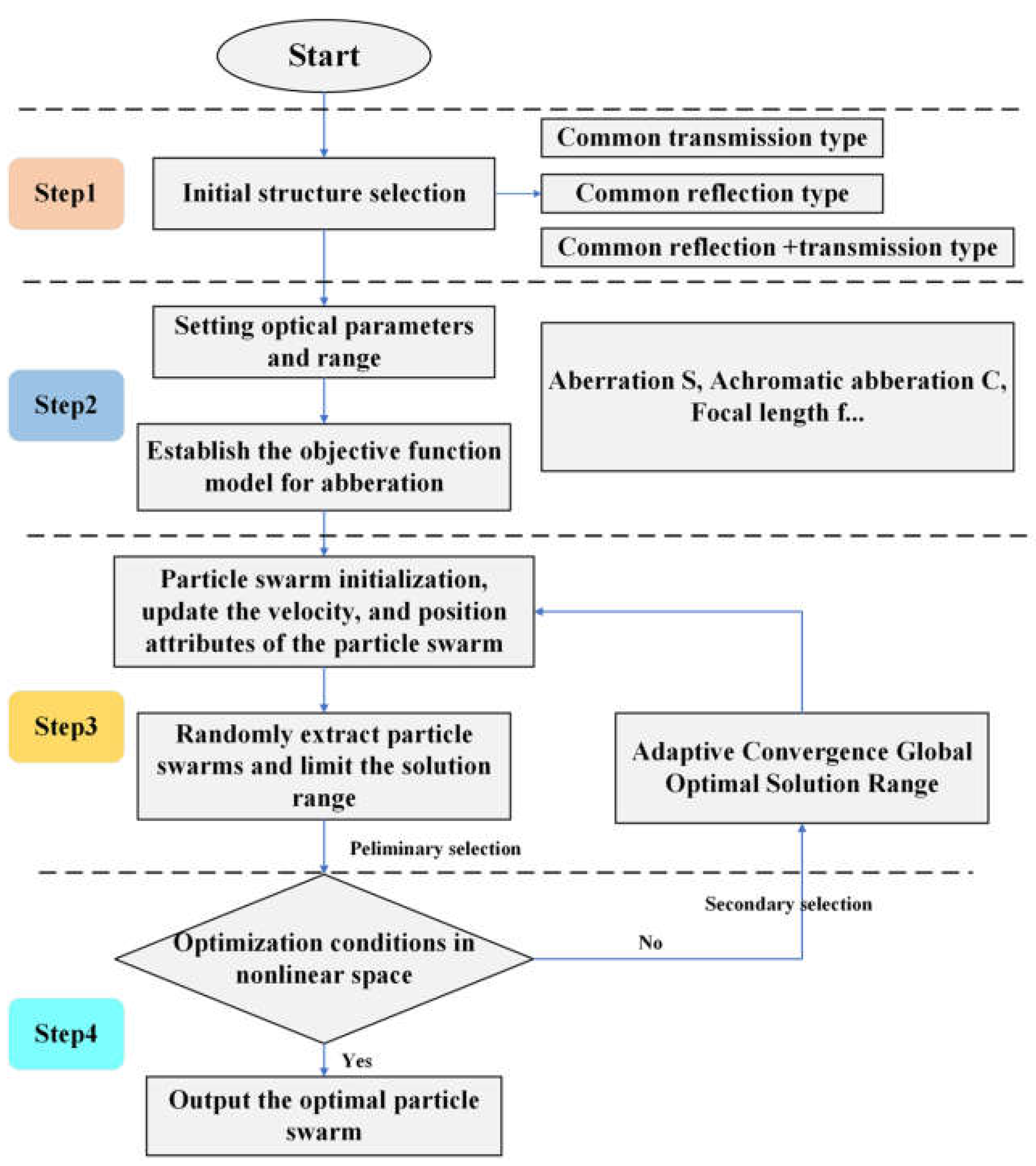
2.1. Adaptive Particle Swarm Optimization Algorithm

The original PSO algorithm is to simulate the predation behavior of birds. To quickly get the food at an unknown location, an objective function is set to represent the current location. The biological “memory” function can be realized in the process of continuous updating and iteration, and the optimal path of the unknown food can be finally obtained. PSO expresses a strategy of seeking the optimal solution. It takes the objective function value as the judging standard. In the d-dimensional space, the particles are divided into two directions of iteration, where c 1 r 1 ( p i d k x i d k ) and c 2 r 2 ( p g d k x i d k 1 ) represent, respectively, the particles in the form of reducing the vector difference, the process of approaching the local optimal solution, and the process of approaching the global optimal solution, are completed in the iteration. For information sharing, the velocity and position of each particle are updated as follows:
v i d k + 1 = ω v i d k + 1 + c 1 r 1 ( p i d k x i d k ) + c 2 r 2 ( p g d k x i d k 1 )
x i d k + 1 = x i d k + v i d k + 1
where k is the number of iterations, ω is the inertia weight, c 1 and c 2 are the learning factor, respectively, r 1 and r 2 are the random number within [0,1], respectively. Similarly, x i d k and v i d k are the particle i velocity and position of the k iteration, respectively. p i d k is the location of the local best solution and the results are simplified to P b e s t . p g d k is the location of the global best solution and the results are simplified to G b e s t . When PSO is applied to solve the optical initial structure, there are some problems, such as slow local convergence rate and local optimum caused by the multi-peak problem, which needs to be further improved. Since the particles are ergodic in the global solution process, we propose an adaptive particle swarm optimization algorithm (APSO). In the iteration process, the inertia weight represents the memory process of “particles” alternating iterations. We tend to set inertia weight as adaptive variables. As a result, the objective function of particles is defined as:
ω = ω min + ( ω max ω min ) ( γ γ min ) γ ¯ γ min , γ γ ¯ ω max , γ > γ ¯
where γ is the fitness value on the current search direction, where γ min and γ max are the minimum and maximum values, respectively. Generally, the default ω is 0.6 to achieve the above-desired optimization goal. Therefore, starting from 0.6, ω min and ω max represent the minimum inertia weight and maximum inertia weight of the current particle, respectively. If the current particle fitness is better than the average fitness of all particles, it indicates that the current position of the particle is close to the global optimal solution, and the inertia weight tends to be smaller, so as to protect the particle. If the current particle fitness is worse than the average fitness of all particles, it indicates that the particle needs to approach the global optimal search area, and the inertia weight tends to be larger. The learning factor values c 1 and c 2 , ranging from 0.5 to 2, are effective in optimizing the optical design [19,20,21]. Thus, under general conditions, if particle fitness is less than the average fitness, the inertia weight should be increased. If particle fitness is greater than the average fitness, the inertia weight should be reduced. The results show that no matter what the inertia weight is, the particles tend to approach the global optimum search area.

2.2. Multi-Level Screening Principle and Optimal Design Method

The APSO algorithm can be directly used to search for the optimal solution for paraxial imaging parameters. Here, we propose the principle of multi-level screening and establish a model for solving the optimal solution of an unknown optical system. The process of an optimal solution for the proposed APSO algorithm is depicted in Figure 1. The specific implementation steps are as follows:
Step 1: The optical system is selected according to the actual imaging requirements. We divide the configuration of the optical system into two types: transmission type and reflection type, which can simplify the initial structure model.
Step 2: After the selected optical configuration is determined, the range of some optical parameters such as the focal length f and wavelength λ , etc. The model of aberration/achromatic objective function is established. If the optical system is a reflective system, taking the obscuration ratio α = [ α 1 , α 2 α n ] , magnification β = [ β 1 , β 2 β n ] , and quadratic spherical coefficient k = [ k 1 , k 2 k n ] as particle parameters to construct an objective function with the minimum total aberration of the system as 0, and eliminate the aberration as much as possible to achieve the optimal design goal. If the optical system is a transmissive system, taking the optical power φ = [ φ 1 , φ 2 φ n ] , the Abbe number of the glass v = [ v 1 , v 2 v n ] ,the distance between lenses d = [ d 1 , d 2 d n ] as particle parameters to construct the objective function of achromatic, and the method of eliminating chromatic aberration as much as possible achieves the purpose of optimal design [22,23,24,25].
When the optical system is a reflective system, on the basis of the third-order aberration theory and the vector aberration analysis model, we set up a nonlinear particle swarm between aberration and optical structure parameters, and list different particle swarms, where i represents the i-th mirror, j represents the j-th particle swarm:
P a r t i c l e 1 [ ( α 11 , α 21 , α i 1 ) , ( β 11 , β 21 , β i 1 ) , ( k 11 , k 21 , k i 1 ) ] P a r t i c l e 2 [ ( α 12 , α 22 , α i 2 ) , ( β 12 , β 22 , β i 2 ) , ( k 12 , k 22 , k i 2 ) ] P a r t i c l e j [ ( α 1 j , α 2 j , α i j ) , ( β 1 j , β 2 j , β i j ) , ( k 1 j , k 2 j , k i j ) ]
Monochromatic aberrations mainly include: spherical aberration, coma, astigmatism, field curvature, and distortion, which are represented by S, S, S, S, S, respectively. The objective function of the third-order aberration of the reflection structure is: Then, the corresponding fitness function is:
S = i = 1 5 S i = A α 1   β 1 α 2   β 2 M   M α i   β i k 1 k 2 M k i
where A is an i × 1 dimensional constant matrix.
When the optical system is a transmission system, on the basis of the apochromatic theory and the gaussian optical analysis model, we set up a nonlinear particle swarm between chromatic aberration and optical structure parameters, and list different particle swarms. Similarly, where i represents the i-th particle mirror, j represents the j-th particle swarm:
P a r t i c l e 1 [ ( φ 11 , φ 21 , φ i 1 ) , ( v 11 , v 21 , v i 1 ) ] P a r t i c l e 2 [ ( φ 12 , φ 22 , φ i 2 ) , ( v i 1 , v i 2 , v i 2 ) ] P a r t i c l e j [ ( φ 1 j , φ 2 j , φ i j ) , ( v 1 j , v 2 j , v i j ) ]
Then the corresponding objective function is:
m = 1 M C I = h 2 ( φ 1 v 1 + φ 2 v 2 + + φ m v m ) = 0
Step 3: Initialize the particle swarm optimization algorithm, and iteratively update the global optimal speed and position of the particle swarm selected through the initial screening. When the optical system is a reflection system, based on the above constraints, it can be seen that the goal is to make the third-order aberration coefficient as small as possible. Then, the optimization function of the third-order aberration is set as:
S o p t i m a l = lim S 0
Based on the individual needs of a specific initial particle swarm, the boundary conditions of each parameter are set, that is, the boundary conditions of the d-dimensional search space are determined, the function fitness of each iteration is calculated, and the particles iteratively solve the initial particle swarm in two directions. Then, the global optimal particle swarm parameters are obtained as follows:
α b e s t = [ α 1 , α 2 α i ] β b e s t = [ β 1 , β 2 β i ] K b e s t = [ K 1 , K 2 K i ]
If the optical system is a transmission system. Similarly, the goal is to make the chromatic aberration coefficient as small as possible. Then, the achromatic optimization function is as follows:
C I o p t i m a l = lim C I 0
Similarly, searching for the global optimal particle in space with limited boundary conditions is expressed as follows:
φ b e s t = [ φ 1 , φ 2 φ i ] v b e s t = [ v 1 , v 2 v i ]
If the optical system is a common reflection and transmission type system. Firstly, the parameters of the reflection type optical system are calculated, and after determining the best parameters of the reflection type optical system, then, the optimal solution h filtered out of the reflection system is substituted into the transmission system; if it is a common transmission and reflection system, the same can be proved.
Step 4: The common aperture system is divided into multiple single imaging systems. Whether or not a common aperture system, if it is a common aperture optical system, take the optimal parameters of the mirrors that have been solved and substitute them into step 2 as a constant term to continue to solve the optical parameters of each sub-system. If it is a single aperture system, whether it meets the condition that the optimal solutions in the nonlinear space, if so, the particle swarm with the optimal optical initial structure will be finally output.

3. APSO Calculation and Result

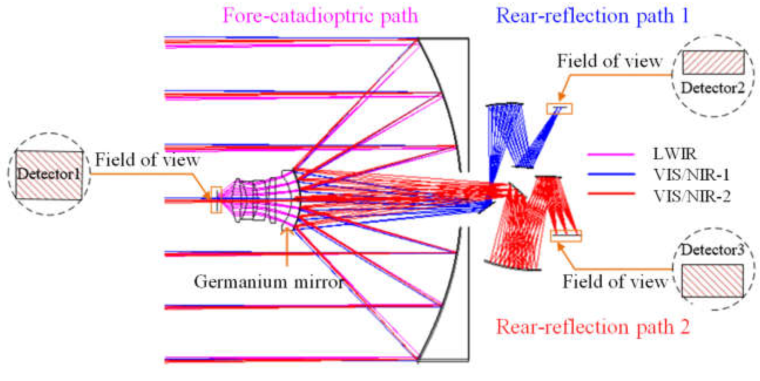
3.1. Initial Layout of Three-Dimensional Compact System

In order to verify the feasibility of the APSO algorithm, we present an initial structural scheme combining reflection type and transmission type, which can realize the three-dimensional compact design of the multi-source common aperture optical system. The system layout is shown in Figure 2. The optical layout is designed by using a dichroic mirror that works in a transflective mode instead of a reflective mode. The dichroic mirror is placed coaxially with the primary mirror, which has the color separation function of transmitting long-wave infrared light and reflecting visible light and near-infrared light. This system can work in the visible light band (0.45–0.76 μm), near-infrared band (0.76–0.9 μm), and long-infrared band (8–12 μm). Therefore, there are three optical paths in the optical system, which share a primary mirror. First of all, the light is reflected by the primary mirror and then converged to the dichroic mirror, realizing the first splitting of the light and duplicating the field of view of the whole system. Thus, the whole optical system is divided into two parts: the fore-catadioptric system and the rear-reflection system. We further split the space of the rear-reflection system into two light paths by dividing the field of view after the first image plane. The final optical system includes a fore-catadioptric path, a rear-reflection path 1, and a rear-reflection path 2.
The dichroic mirror is the core component to determine the imaging quality, and its material is required for good surface accuracy under the action of gravity and temperature. The specific requirements for the material are as follows: (a) It should have a lower density to facilitate lightweight; (b) it should have a larger elastic modulus to reduce the deformation under gravity; (c) it should have a lower thermal expansivity to reduce thermal deformation; (d) it should have a larger transmittance to facilitate coating. By analyzing the parameters of the materials, compared with traditional materials such as silicon, fused quartz, and SiC, germanium has greater density and coating transmittance. Considering the comprehensive performance, we choose germanium as the dichroic mirror material for this system. It is coated with a high-reflectance film designed for a 0.45–0.9 μm band. According to the initial structural characteristics of the common reflection-transmission of the common-aperture system, the optimization process of the APSO algorithm is shown in Figure 3.

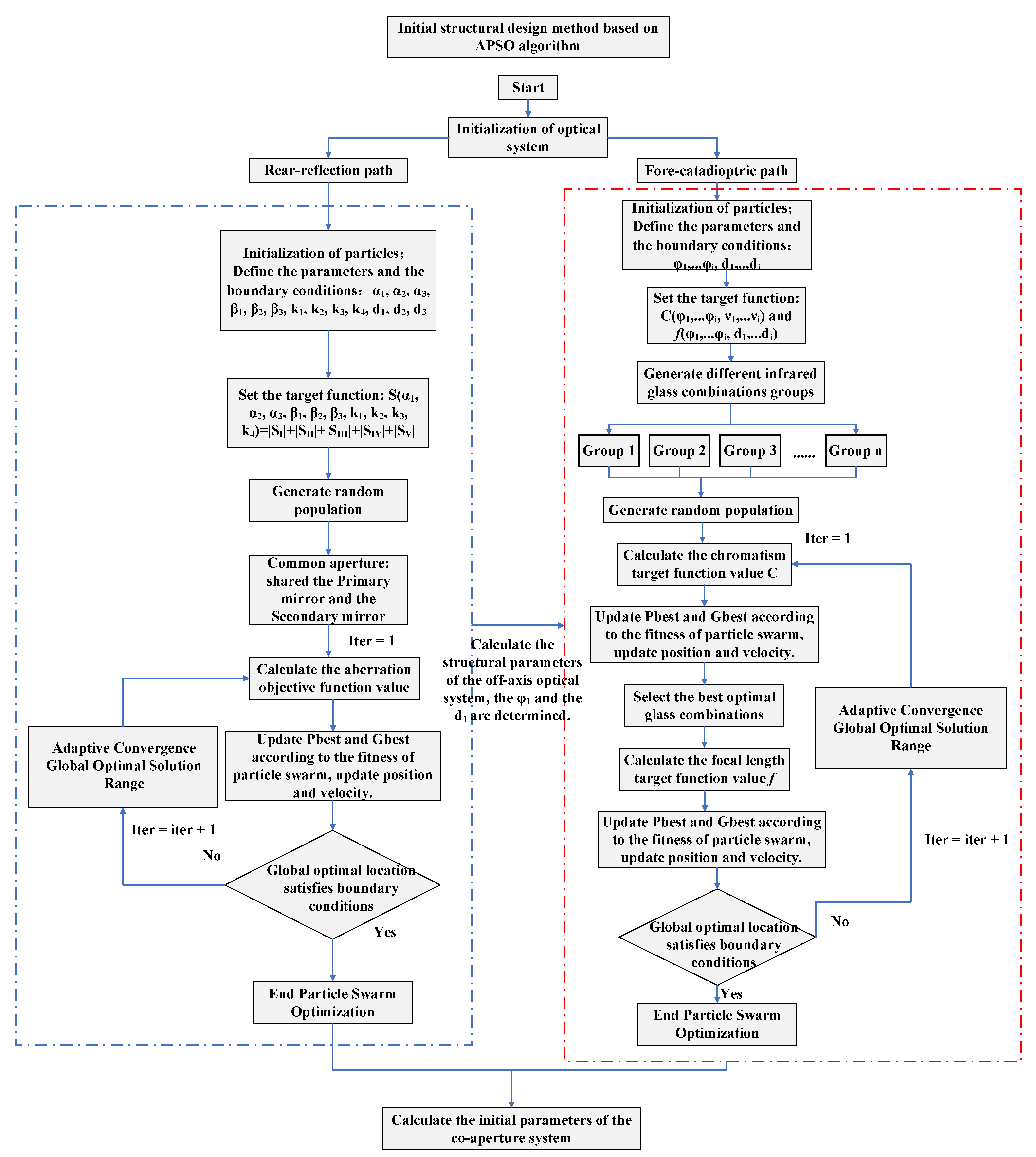
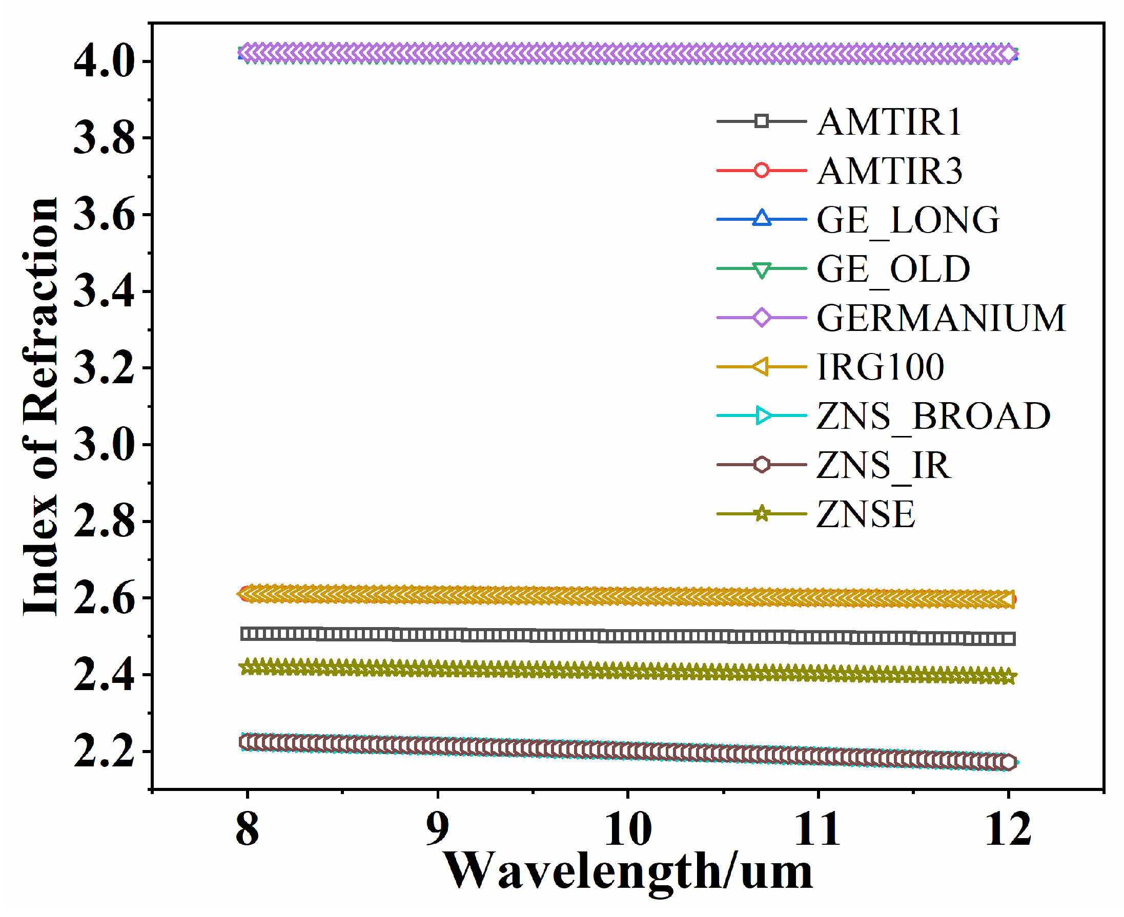
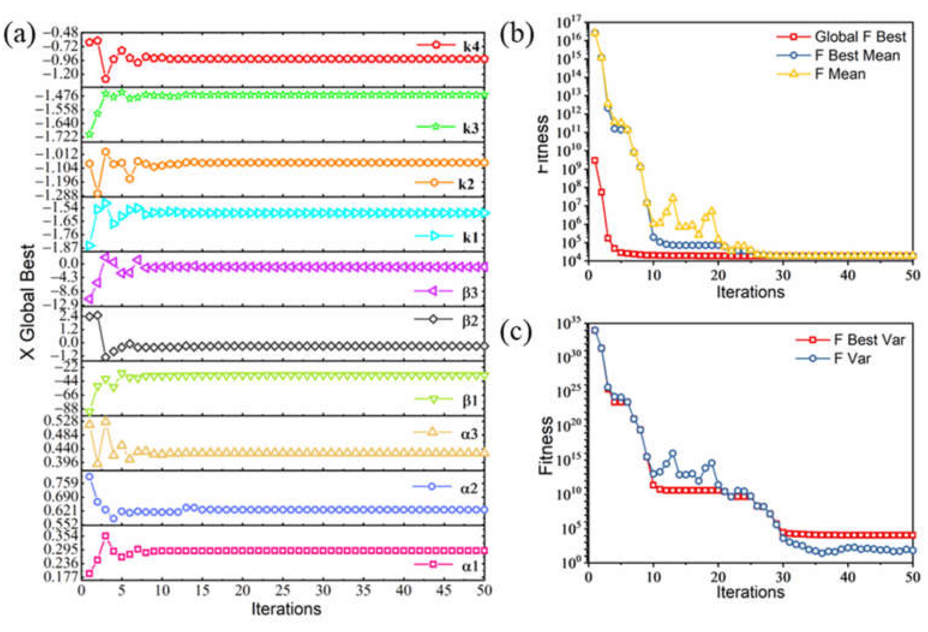
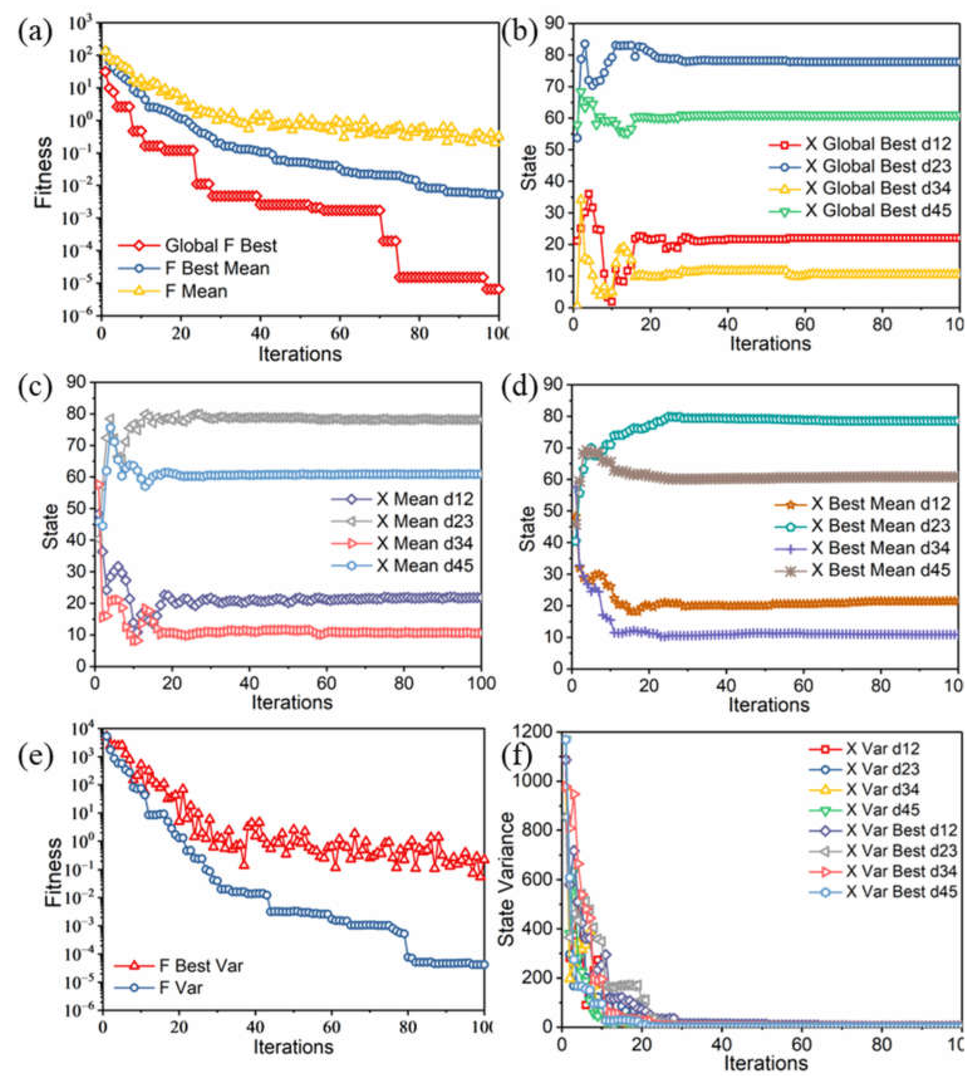
3.2. Initial Structure Calculation Based on Adaptive Algorithm

In this paper, the initial structure optimization of the rear-reflection system optics in the visible-near infrared band of the common aperture system needs to eliminate all optical aberrations except chromatic aberration, including spherical aberration S, coma aberration S, astigmatism S, field curvature S and distortion S. Optical parameters that determine optical aberrations include obscuration ratio α1, α2, α3, magnification β1, β2, β3, and quadratic spherical coefficient k1, k2, k3, k4. In addition, considering the reasonable layout of the subsequent optical paths of the rear-reflection system, the distance d1, d2, d3, and d4 between the mirrors should also be restricted. The objective function of the APSO algorithm for the initial structure of the reflection optical system is set as: S (α1, α2, α3, β1, β2, β3, k1, k2, k3, k4) = |S| + |S| + |S| + |S| + |S|, that is, the search space of the APSO is (α1, α2, α3, β1, β2, β3, k1, k2, k3, k4) ∈SpD (D = 10). The particle search range is set as shown in Table 1.
The long-wave infrared band fore-catadioptric system mainly considers eliminating chromatic aberration C, and the function of chromatic aberration is C = ∑h2φi/νi. The number of lenses of the fore-catadioptric system is set to 5. The structural parameters that determine the chromatic aberration include the optical power φ1, φ2, φ3, φ4, φ5 of each lens, and the Abbe numbers ν1, ν2, ν3, ν4, ν5 of each lens. In addition to chromatic aberration, distances between lenses d12, d23, d34, and d45 are also parameters that must be considered in optimizing the initial structure. Therefore, when optimizing the initial structure of the catadioptric branch, it is necessary to use a combination of two APSO algorithms to construct the objective functions C (φ1, ... φ5, ν1, ... ν5) and f (φ1, ... φ5, d12, ... d45), respectively. The material selection range of each lens is shown in Figure 4.
According to the formula ν = (nc − 1)/(nminnmax) and the above tables, we can calculate the Abbe number for each material in the long-wave infrared band. For the fore-catadioptric system composed of five lenses, there are 504 available combinations of materials based on the above-mentioned material library. We utilize the APSO algorithm to optimize all material combinations and screen out the optimal material combination for the transmission system. The search space of the first PSO algorithm is (φ1, φ2, φ3, φ4, φ5) ∈ Sp1 D (D = 5). Then, the first particle search range is set as shown in Table 2.
The search space of the secondary particle swarm optimization is (d12, d23, d34, d45) ∈ Sp2 D (D = 4). Then, the secondary particle search range is set as shown in Table 3.
Table 3 shows the boundary conditions of each parameter of the objective function of the four-reflection system, the acceleration parameters of the APSO algorithm, the adaptive weight parameters, the number of particles in the particle swarm and the number of iterations, etc. For the optimal result search of the APSO algorithm for the four-reflection system, the parameter boundary conditions that limit the distance between the mirrors of each order are set as d1 ∈ [−400,−100], d2 ∈ [1000,1500], d3 ∈ [−500, −300]. As can be seen from Figure 3, the APSO algorithm searches for the parameter results and the distance between the mirrors of each order. If the set boundary conditions are satisfied, the search results are output as the initial parameters of the four-reflection structure. If the set boundary conditions are not met, then the APSO search is performed again until the set boundary conditions are met, and then the results are output. The optimization results of the APSO algorithm for the four-reflection system are shown in Figure 5.
Figure 5a shows the search results of the APSO algorithm for each parameter of the objective function S (α1, α2, α3, β1, β2, β3, k1, k2, k3, k4). Figure 5b shows the global optimal value of the objective function, the average of the previous global optimal value during the search process of each particle and the average of the current global optimal value approaching the stable value, which are 1.843 × 10⁴, 1.848 × 10⁴, and 1.887 × 10⁴, respectively. Figure 5c shows the variance value of the previous global optimal value during the search process and the variance value of the current global optimal value of each particle of the objective function. With continuous iterations, the variance of the current global optimal value tends to a stable low value of 68.1. According to the optimization results of the APSO algorithm, the initial parameters of the four-reflection structure can be calculated.
According to the parameters of the APSO algorithm in Table 3, the optimal optical power distributions of 504 kinds of material combinations are searched respectively. In addition, the optimization results obtained are shown in Figure 6, that is, the fitness calculation values of the optimal objective function for 504 material groups, from which we choose the optimal material combination and optical power distribution scheme, as shown in Table 4.
When selecting the material combination and optical power distribution scheme, we also fully consider that the material of the beam splitter is germanium, the optical power of the primary mirror, the distance between the primary mirror and the secondary mirror, and some distance ranges in the refraction system are shown in Table 3. In addition, the optical power parameters are also determined accordingly. According to the optimal parameters in Table 4, φ1,...,φ5 in the objective function f(φ1,...φ5, d12,...d45) of the secondary APSO algorithm are fixed values, and the optimal value of the objective function is set (f(φ1,...φ5, d12,...d45) ) mm. The boundary conditions and APSO algorithm parameters of each lens spacing are shown in Table 3, and the obtained APSO search results are shown in Figure 7.
Figure 7a shows the iterative result of the global optimal value of the objective function, the mean value of the previous global optimal value of the objective function, and the mean value of the current global optimal value of the objective function. It can be seen that the optimal search value of the focal length of the initial structure is 600.0001 mm. From Figure 7b–d), the iterative process of the global optimal values of the four target parameters, the iterative process of the global optimal mean value of the parameters and the iterative process of the previous global optimal mean value of the parameters can be obtained. In addition, the initial lens spacing structures are 22.06 mm, 77.847 mm, 10.42 mm, and 61.036 mm, respectively. It can be seen from Figure 7e,f that the objective function and the objective parameters tend to be stable through continuous iterations, which proves that all particles in the PSO algorithm are searching for a unified optimal solution

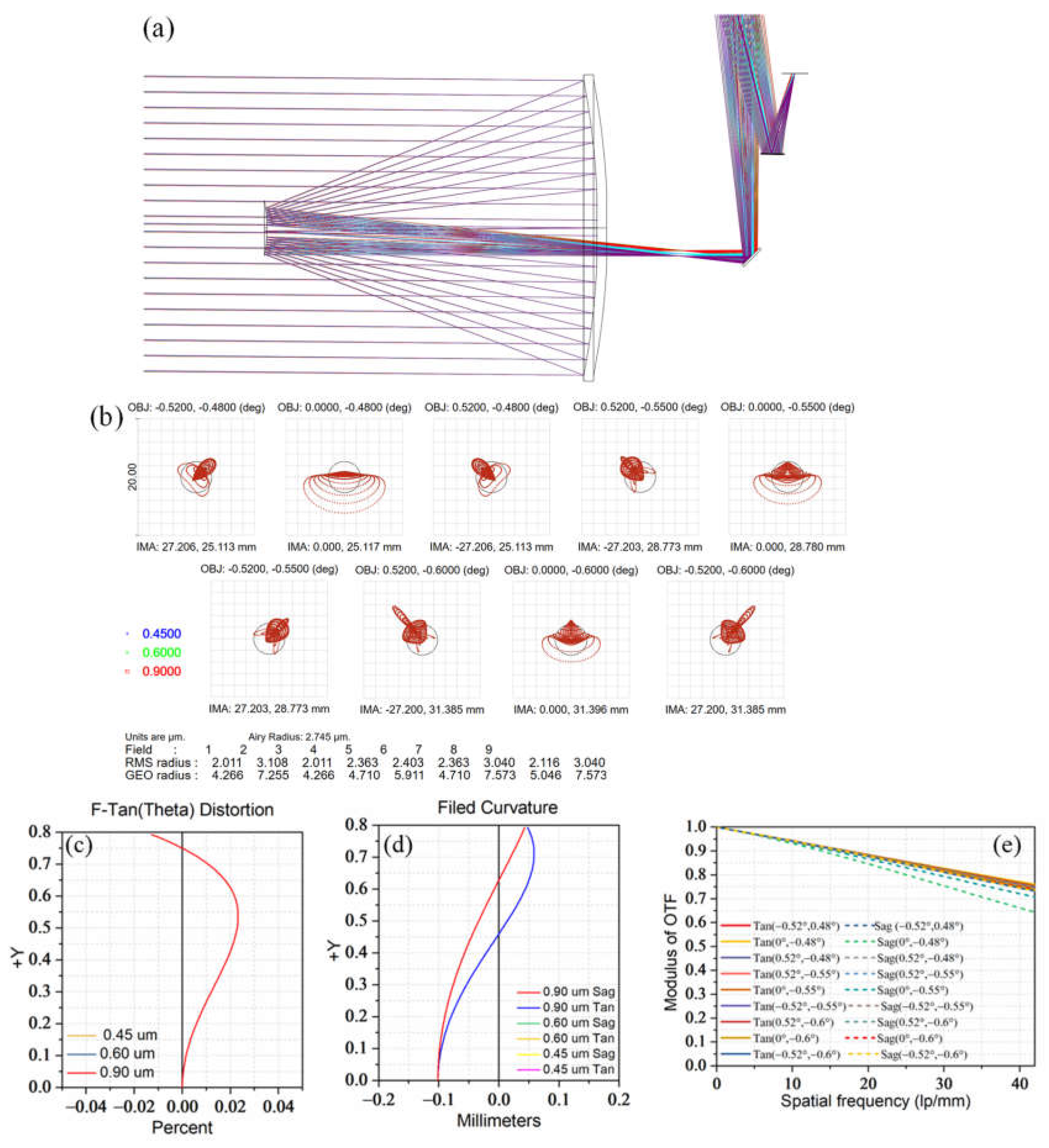
4. Design Example and Results Discussion

The optimal initial optical parameters are substituted into Zemax for further optimization design. In the optimization of the reflection system, first of all, under the focal length is the same, the visible/near-infrared light paths will interfere and block. To solve this problem, when setting the field of view, add the field of view in the meridian direction to control the light blocking. Then the sagittal field of view is added to enlarge the imaging width, and the horizontal distance between the field of view and the beam splitter is controlled to ensure that the two light paths are independent and not blocked. On the basis of the even aspheric surfaces of three mirrors and four mirrors in the reflection system, the fourth and sixth term of high-order aspheric coefficients are added, which ensures the constraints conditions (quadratic spherical coefficient, curvature, occlusion ratio) in the initial structure solution, and at the same time, obtains high imaging quality. The final optimized results are shown in Table 5.
As shown in Figure 8a, the rear-reflection path1 is the secondary imaging. The final optical structure consists of four reflective mirrors and a 45° direction folding mirror. The folding mirror is added after the main image plane, which makes the optical structure more compact, reduces the difficulty of assembly, and shortens the total length of the system. Figure 8b shows the spot diagram of the whole FOV of the system, from which we can see that the maximum RMS radius is less than one single pixel (11 µm) over the full FOV. As shown in Figure 8c, the maximum amount of distortion is less than 0.05%. As shown in Figure 8d, the maximum field curvature is 0.2 mm, which effectively eliminates field curvature. Figure 8e shows the transfer function curve of the optical system. It can be seen that the MTF value at the full field of view exceeds 0.6 at the Nyquist frequency45 lp/mm, and the MTF curve display system of each field of view has very good image quality.
The rear-reflection path 2 is shown in Figure 9a. The final optical structure consists of four reflective mirrors and a 45° direction folding mirror. Figure 9b shows the spot diagram of the whole FOV of the system, from which we can see that the maximum RMS radius is less than one single pixel (4.5 µm) over the full FOV. As shown in Figure 9c, the maximum amount of distortion is less than 0.05%. As shown in Figure 9d, the maximum field curvature is 0.05 mm, which effectively eliminates field curvature. Figure 9e shows the transfer function curve of the optical system. It can be seen that the MTF value at the full field of view exceeds 0.4 at the Nyquist frequency118 lp/mm, approaching the diffraction limit.
In the optimization of the transmission system, the fore-catadioptric path adopts a catadioptric scheme layout, which uses a combination of primary mirror and lens group. This design of the infrared imaging branch cleverly utilizes the characteristics of the large aperture and small focal length of the primary mirror. After being condensed by the primary mirror, the light directly enters the fore-catadioptric path, and the optical system has rotational symmetry. The primary mirror will not produce chromatic aberration. At the same time, based on the solution of the achromatic and achromatic initial structure, the curvature and lens distance are set as variables in a certain range. Set the lens material (GE_LONG AMIR 3 AMIR 3) selected in the APSO algorithm to a fixed amount. There is a small deviation between the final optimization result and the initial structure. The final optimized results are shown in Table 6.
The design result of the fore-catadioptric path is shown in Figure 10a. The final optical structure includes a reflecting mirror and an aberration correction device composed of five transmitting mirrors. Figure 10b shows the transfer function curve of the optical system. It can be seen that the MTF value at the full field of view exceeds 0.3 at the Nyquist frequency 42 lp/mm, approaching the diffraction limit. Figure 10c shows the longitudinal chromatic aberration of the optical system. It can be seen from the curve that the chromatic aberration and the secondary spectrum are both less than 0.02, and the apochromatic aberration has been well resolved. As shown in Figure 10d, the maximum field curvature is 0.02 mm, which effectively eliminates field curvature. As shown in Figure 10e, the maximum amount of distortion is less than 0.5%.
The final optical imaging system is shown in Figure 11. The total length of the system is 1000 mm. Although the design method of structural division effectively divides the field of view, a certain amount of off-axis is generated during the imaging process. Therefore, in the overall optical design, by controlling the distance between the edge light and the endpoint of the reflector, secondary occlusion is avoided in the structural design, and a certain optical interval is reserved for the subsequent hood and mechanical design of the optical system.

5. Conclusions

In this paper, an APSO algorithm is used to solve the optimal initial structural parameters of the optical system. Based on ray tracing theory, we propose a sub-structure design method combining aberration and chromatic aberration correction, formulating multilevel screening principles and setting constrained boundary conditions, which effectively improves the solution accuracy of particle swarm optimization. Furthermore, we design a common-aperture imaging system including a transmission and reflection system to evaluate the validity of the proposed APSO algorithm. Firstly, a three-dimensional compact optical system scheme is established. The system adopts the combination of the secondary mirror, the beam splitter plane mirror, and the remaining mirror groups, which improves the space utilization ratio. Then, according to the specific imaging requirements, the initial structural model of the four-reflection system and transmission system to eliminate aberration and transmission achromatic is established. Finally, the optimal parameters are selected by the APSO algorithm as the input of optical design software to further optimize the design. From the design results of the system, the algorithm can well realize the three-dimensional compact design of the optical system. This paper provides theoretical guidance for the optimal initial structure solution method of the multi-mode common-aperture optical system and the configuration design of the three-dimensional compact optical system.

Author Contributions

W.Y. designed the optical system, conceived, and wrote the first version of the paper; G.J. conceived the original ideas and revised the paper; X.Y. managed the projects that fund this paper. All authors have read and agreed to the published version of the manuscript.

Funding

This research was supported by the National Natural Science Foundation of China (NSFC) (No. 62171430), National Natural Science Foundation of China (NSFC) (No. 62101071), Jilin Provincial Natural Science Foundation. (No. 20210101099JC), 2019 Zhuhai Innovation and Entrepreneurship Team Project (No. ZH0405190001PWC).

Institutional Review Board Statement

Not applicable.

Informed Consent Statement

Not applicable.

Data Availability Statement

Not applicable.

Acknowledgments

We gratefully acknowledge Yupeng Chen for useful discussion and help in optical design.

Conflicts of Interest

The authors declare no conflict of interest.

References

  1. Antipa, N.; Kuo, G.; Heckel, R.; Mildenhall, B.; Bostan, E.; Ng, R.; Waller, L. DiffuserCam: Lensless single-exposure 3D imaging. Optica 2018, 5, 1–9. [Google Scholar] [CrossRef]
  2. Cui, S.C.; Zhen, X.B.; Wang, Z.; Yang, S.Z.; Zhu, W.Y.; Li, X.B.; Huang, H.H.; Wei, H.L. Toward a new radiative-transfer-based model for remote sensing of terrestrial surface albedo. Opt. Lett. 2015, 40, 3842–3845. [Google Scholar] [CrossRef] [PubMed]
  3. Carles, G.; Harvey, A.R. Multi-aperture imaging for flat cameras. Opt. Lett. 2020, 45, 6182–6185. [Google Scholar] [CrossRef]
  4. Mait, J.N.; Athale, R.; van der Gracht, J. Evolutionary paths in imaging and recent trends. Opt. Express 2003, 11, 2093–2101. [Google Scholar] [CrossRef] [PubMed]
  5. Mico, V.; Zalevsky, Z.; Garcia, J. Superresolution optical system by common-path interferometry. Opt. Express 2006, 14, 5168–5177. [Google Scholar] [CrossRef]
  6. Vizgaitis, J.N.; Hastings, A. Dual band infrared picture-in-picture systems. Opt. Eng. 2013, 52, 061306. [Google Scholar] [CrossRef]
  7. Guo, D.B.; Yin, L.; Yuan, G. New automatic optical design method based on combination of particle swarm optimization and least squares. Optics Express 2019, 27, 17027–17040. [Google Scholar] [CrossRef]
  8. Guo, Y.L.; Yu, X.; Tao, Y.; Jiang, X. Design of Visible and IR infrared Dual-Band Common-path Telescope System. In Proceedings of the International Conference on Optical Instruments and Technology (OIT)/6th Conference of Optical Systems and Modern Optoelectronic Instruments, Beijing, China, 28–30 October 2017; Volume 10616, p. 1061613. [Google Scholar]
  9. Jeong, D.; Lee, J.H.; Jeong, H.; Ok, C.M.; Park, H.W. Infrared Dual-field-of-view Optical System Design with Electro-Optic/Laser Common-aperture Optics. Curr. Opt. Photonics 2018, 2, 241–249. [Google Scholar]
  10. Yuan, L.Y.; He, Z.P.; Lv, G.; Wang, Y.M.; Li, C.L.; Xie, J.N.; Wang, J.Y. Optical design, laboratory test, and calibration of airborne long wave infrared imaging spectrometer. Opt. Express 2017, 25, 22440–22454. [Google Scholar] [CrossRef]
  11. Liu, X.; Chang, J.; Zhong, Y.; Feng, S.; Song, D.L.; Hu, Y.Y. Optical design of a simultaneous polarization and multispectral imaging system with a common aperture. J. Mod. Opt. 2020, 67, 462–468. [Google Scholar] [CrossRef]
  12. de Albuquerque, B.F.C.; de Sousa, F.L.; Montes, A.S. Multi-objective approach for the automatic design of optical systems. Opt. Express 2016, 24, 6619–6643. [Google Scholar] [CrossRef]
  13. Schifano, L.; Smeesters, L.; Berghmans, F.; Dewitte, S. Optical System Design of a Wide Field-of-View Camera for the Characterization of Earth’s Reflected Solar Radiation. Remote Sens. 2020, 12, 2556. [Google Scholar] [CrossRef]
  14. Tang, R.R.; Zhang, B.Q.; Jin, G.F.; Zhu, J. Multiple surface expansion method for design of freeform imaging systems. Opt. Express 2018, 26, 2983–2994. [Google Scholar] [CrossRef]
  15. Yang, M.; Xu, W.B.; Sun, Z.Y.; Wu, H.; Tian, Y.Z.; Li, L.T. Mid-wave infrared polarization imaging system for detecting moving scene. Opt. Lett. 2020, 45, 5884–5887. [Google Scholar] [CrossRef]
  16. Clerc, M.; Kennedy, J. The particle swarm-Explosion, stability, and convergence in a multidimensional complex space. IEEE Trans. Evol. Comput. 2002, 6, 58–73. [Google Scholar] [CrossRef] [Green Version]
  17. Li, R.C.; Feng, L.J.; Xu, K.J.; Wang, N.; Fan, X.W. Optical design of an integrated imaging system of optical camera and synthetic aperture radar. Opt. Express 2021, 29, 36796–36812. [Google Scholar] [CrossRef]
  18. Chen, Y.; Gao, M.; Song, X. Method to design the common aperture multi-band optical system based on the PSO algorithm. Opt. Express 2021, 29, 18325–18335. [Google Scholar] [CrossRef]
  19. Yu, X.; Wang, H.; Yao, Y.; Tan, S.; Xu, Y.; Ding, Y. Automaic design of a mid-wavelength infrared dual-conjugate zoom system based on particle swarm optimization. Opt. Express 2021, 29, 14868–14882. [Google Scholar] [CrossRef]
  20. Oiknine, Y.; August, I.; Stern, A. Multi-aperture snapshot compressive hyperspectral camera. Opt. Lett. 2018, 43, 5042–5045. [Google Scholar] [CrossRef]
  21. Parsopoulos, K.E.; Vrahatis, M.N. Recent approaches to global optimization problems through Particle Swarm Optimization. Nat. Comput. 2002, 1, 235–306. [Google Scholar] [CrossRef]
  22. Menke, C. Application of particle swarm optimization to the automatic design of optical systems. Proc. SPIE 2018, 10690, 106901A. [Google Scholar]
  23. Fan, Z.C.; Wei, S.L.; Zhu, Z.G.; Ma, D.L. Globally optimal first-order design of zoom systems with fixed foci as well as high zoom ratio. Opt. Express 2019, 27, 38180–38190. [Google Scholar] [CrossRef] [PubMed]
  24. Qin, H. Article swarm optimization applied to automatic lens design. Opt. Commun. 2011, 284, 2763–2766. [Google Scholar] [CrossRef]
  25. Duma, V.-F. Radiometric versus geometric, linear, and nonlinear vignetting coefficient. Appl. Opt. 2009, 48, 6355–6364. [Google Scholar] [CrossRef]
Figure 1. Multi-level screening model based on adaptive particle swarm optimization.
Photonics 09 00807 g001
Figure 2. Initial layout of three-dimensional compact system.
Photonics 09 00807 g002
Figure 3. Flow chart of APSO algorithm.
Photonics 09 00807 g003
Figure 4. Material selection range and refractive index.
Photonics 09 00807 g004
Figure 5. Search results of APSO algorithm for four-reflection system; (a) the parameter search results of the objective function; (b) the optimization results of objective function value of APSO algorithm; (c) the optimization results of objective function variance value of APSO algorithm.
Photonics 09 00807 g005
Figure 6. Optimal particle swarm distribution for 504 material combinations.
Photonics 09 00807 g006
Figure 7. Search results of the APSO algorithm for the fore-catadioptric system: (a) the optimization result of objective function value of the APSO algorithm; (b) the global optimal parameters search results of the objective function; (c) the mean of the current global optimal parameters search results of the objective function; (d) the mean of the previous global optimal parameters results during the search process; (e) the optimization results of objective function variance value of APSO algorithm; (f) the results of the optimal parameters variance value.
Photonics 09 00807 g007
Figure 8. The rear-reflection path 1. (a) Optical layout diagram. (b) Spot diagram. (c) Distortion of the different wavelengths. (d) Field curvature of the different wavelengths. (e) Modulation transfer function diagram.
Photonics 09 00807 g008
Figure 9. The rear-reflection path 2. (a) Optical layout diagram. (b) Spot diagram. (c) Distortion of the different wavelengths. (d) Field curvature of the different wavelengths. (e) Modulation transfer function diagram.
Photonics 09 00807 g009
Figure 10. Fore-catadioptric path. (a) Optical layout diagram. (b) Modulation transfer function diagram. (c) The longitudinal chromatic aberration diagram. (d) Field curvature of the different wavelengths. (e) Distortion of the different wavelengths.
Photonics 09 00807 g010
Figure 11. The overall optical design.
Photonics 09 00807 g011
Table 1. Particle search range of reflective system.
SpD (D = 10)α1, α2, α3 ∈ [0,1]; β1, β2, β3 ∈ [–100,100]; k1, k2, k3, k4 ∈ [–3,3];
APSOwc1c2Niter
wmaxwmin0.60.93050
1.20.6
Table 2. First particle search range of transmission system.
Sp1 D (D = 5)φ1, φ2, φ3, φ4, φ5 ∈ [–500,500]
APSOwc1c2Niter
wmaxwmin0.60.930100
1.20.6
Table 3. Secondary particle search range of transmission system.
Sp2 D (D = 4)d12, d23, d34, d45 ∈ [0,100]
APSOwc1c2Niter
wmaxwmin0.60.930100
1.20.6
Table 4. Optimal material combination and optical power distribution.
LensMaterialOptical Power/mm−1
1Germanium−0.010
2AMTIR30.003
3AMTIR1−0.003
4Ge_LONG0.008
5Ge_LONG0.010
Table 5. Initial parameters of the reflective system.
SurfaceRadius/mmThickness/mmConic
Primary mirror1592.1664−0.99
Secondary mirror290.21041.6/1205.8−1.66
folding mirrorInfinity500/333.80
Tertiary mirror627.3/640.4350/383.2−1.25/1
fourth mirror−802.7/750.6158.5/178.76−1/−2
Table 6. Initial parameters of longwave-infrared system.
SurfaceOptical Power /mm−1Thickness/mmGlass
1st lens−0.0100020GE_LONG
2st lens0.00302820AMTIR3
3st lens−0.00334820AMTIR3
4st lens0.00896845GE_LONG
5st lens0.01029842GE_LONG
Publisher’s Note: MDPI stays neutral with regard to jurisdictional claims in published maps and institutional affiliations.

