1. Introduction
Microwave and light waves are both electromagnetic waves that have had an unparalleled impact on human society over the past 100 years [
1]. In recent decades, microwave technology and light-wave technology have converged, forming a new interdisciplinary field of great innovation and commercial interests, namely microwave photonic technology. The purpose of microwave photonic technology is to process microwave frequency band signals in the optical domain, including for the generation, control, transmission, and distribution of microwave signals by optical methods.
From the point of signal generation, a high-quality microwave source is the basis of all microwave photonic technologies [
2]. To break the bottleneck of frequency and bandwidth in electrical waveform generation, the photonic generation of microwave signals has attracted much interest [
3]. Compared with traditional electronic microwave sources, photonics-based microwave signals have the advantages of high frequency, low phase noise, compact structure, large bandwidth, low loss, wide tuning range, anti-electromagnetic interference, and so on [
2,
4,
5]. Therefore, photonics-based technology shows high long-term stability and reliability, leading to good application prospects.
There have been many methods of photonics-based microwave signal generation, such as the external modulation method [
6,
7], the photoelectric oscillator method [
8], the nonlinear effect of optical fiber [
9,
10], and so on. However, the external modulation method requires a high-quality external radio frequency (RF) source to generate microwave signals, which results in high equipment dependence. In addition, the photoelectric oscillator method does not require external microwave sources, but at the expense of complex structure, numerous devices, and high cost. Moreover, it is well-known that the generation and control of nonlinear effects are difficult.
The heterodyne method is a simple and effective way to generate high-frequency microwave signals [
11]. It is easy to obtain microwave signals by directly beating two independent lasers with different frequencies. However, because the two lasers operate independently and freely, and the phases of the two light waves are not related to each other, the phase-noise performance of the generated microwave signals will deteriorate. Therefore, additional technology is needed to phase-lock the two light waves to generate microwave signals with low phase noise.
The direct optical detection of multi-longitudinal mode lasers can also produce microwave signals. In particular, the potential of mode-locked fiber laser (MLL) with an equal-spacing, phase-locked longitudinal mode to generate high-quality microwave signals has attracted great attention [
12,
13]. A mode-locked fiber laser can be realized through active mode-locking and passive mode-locking [
14,
15,
16,
17,
18]. However, for active mode-locking, the laser is mode-locked by a modulator with an RF signal equal to integral multiples of the longitudinal mode spacing, which leads to a complex structure. Comparatively speaking, passively mode-locked fiber lasers have the capacity of producing ultra-short pulses in a simple configuration. Passively mode-locked fiber lasers have been realized with different mode-lockers, such as carbon nanotubes, graphene saturable absorbers, semiconductor saturable absorber mirrors (SESAMs), and other equivalent saturable absorbers, among which SESAM technology is most widely used due to its high thermal damage threshold, stable structure, and commercial availability [
19,
20,
21,
22].
Through the direct photoelectric detection of the MLL with a certain repetition-rate or combined with specific microwave filters, the required microwave signal can be extracted. However, direct optical detection creates a lack of frequency tunability, resulting in a one-fold microwave signal.
In order to overcome the disadvantages of the above scheme, such as high equipment dependence, complex structure, high cost, and non-adjustable frequency, a MLL with a repetition-rate of up to 1 GHz is used to generate tunable microwave signals through a chirped mixing structure. The ability of direct optical detection of chirped pulses and their delayed replicas to produce tunable microwave signals has been studied theoretically and experimentally. It is known that environmental stability and reliability are the crucial aspects for a system. If non-PM devices are universally used in these systems, these systems will be sensitive to environmental perturbations. Compared with the previous reports [
12,
13], an all-PM system was used in this paper to enhance stability, so that there is no need for additional polarization control. Furthermore, an electronically controlled optical fiber tunable delay line (TDL) was used in the experiment, so that the generation of the microwave signal can be controlled by a computer. Theoretically, the scheme proposed in this paper could select any longitudinal mode of the mode-locked laser. Due to the limitation of the oscilloscope, in this experiment, we only demonstrated the generation of 2–4 GHz microwave signals.
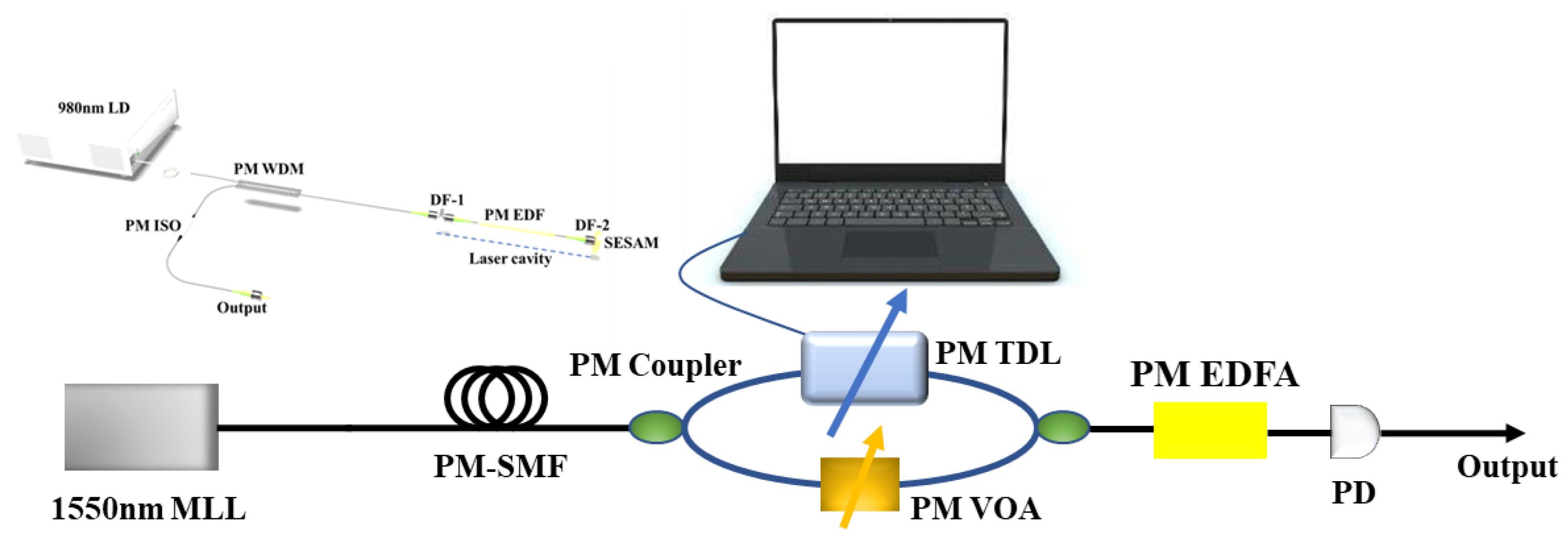
2. Schematic Diagram for Tunable Microwave Signal Generation
Figure 1 illustrates the schematic diagram for the generation of the proposed tunable microwave signal based on a PM 1-GHz MLL. The basic configurations of the PM 1-GHz MLL are depicted in the inset of
Figure 1. The laser cavity is simple and compact, consisting of a ~10 cm PM EDF, two ceramic ferrules, and a piece of SESAM. As a gain medium, both ends of the PM EDF were inserted and glued in a ceramic ferrule and flat-polished. In order to increase the pump efficiency, two different dielectric films (DFs, SiO
2/TiO
2) were coated on both ends of the PM EDF, respectively. On the left side of the PM EDF, the DF-1 exhibits a high transmittance of ~98% at the pump wavelength of 980 nm, as well as a high reflectivity of ~98% at 1550 nm. In contrast, on the right end of the PM EDF, the DF-2 exhibits a high transmittance of ~98% at 1550 nm, as well as a high reflectivity of ~98% at 980 nm. The coated right end is then butt-coupled to a SESAM, which is the key device for the realization of mode-locking. The PM EDF was pumped by a 980 nm laser diode (LD) through a PM wavelength division multiplexer (WDM). The mode-locked optical pulses are then outputted through a PM isolator (ISO), which can prevent unwanted reflections into the laser cavity.
Firstly, the output ultrashort pulse of the MLL is temporally stretched by a piece of PM single-mode fiber (SMF). Then, the chirped pulse train is sent to a Mach–Zehnder Interferometer (MZI) composed of two PM couplers. In the upper arm of MZI, a computer-controlled tunable delay line (TDL) with 5 fs precision is used to tune the delay between the two arms. In the lower arm of MZI, a PM variable optical attenuator (VOA) is utilized for loss balance between the two arms. At the end of the MZI, the pulses overlap with each other. The overlapping pulses are then amplified by an PM erbium-doped fiber amplifier (EDFA). At last, the output from the PM EDFA is converted into the electrical domain by a photodetector (PD). Through proper dispersion management and precise tuning of relative time delay and attenuation, it is promising to realize tunable microwave signal generation. It is worth mentioning that all the devices of the system are polarization-maintaining, which could greatly improve the stability of the system.
3. Theoretical Simulation and Discussion
In order to further understand the principle of tunable microwave signal generation, a theoretical simulation was carried according to Ref. [
12].
First, the pulse sequences of the 1-GHz MLL can be expressed as:
where
E0 is the amplitude of the initial ultrashort pulse-train;
is the pulse width at full-width half maximum (FWHM);
T is the temporal period of the optical pulse train; the chirp parameter
; and Δ
ω is the bandwidth of the pulse train. Moreover, the repetition rate of the pulse train is
frep = 1/
T.
Then, the output pulse train is temporally stretched by a roll of SMF, so the electric field after the SMF can be written as:
where
, and the symbols
β2 and
L represent the second-order dispersion and the length of the SMF, respectively.
Next, the temporally stretched pulse train is sent to an MZI, which is composed of two couplers. In this case, the pulse train is split and delayed. The time delay between the two arms of the MZI is Δ
t. Therefore, the electric field after recombination at the output of the MZI can be expressed as:
Thus, the resultant photocurrent from the PD can be expressed as:
where
is the responsivity of the PD, and the broadened pulse width
τ1 is defined as:
Further, the three time-varying terms on the right side of (4) can each be simply expressed as:
where the generated frequency
fc can be written as:
This equation clearly shows that the generated microwave frequency fc varies with the time delay Δt, the broadened pulse width τ1, and the changed chirp parameter C1. Furthermore, both τ1 and C1 are a function of the dispersion parameter β2·L. Therefore, the generated microwave frequency is determined by two parameters, namely the time delay and the dispersion. In other words, properly tuning the time delay and dispersion are promising for the realization of the tunable microwave signal generation.
Meanwhile, from the perspective of the frequency domain, the Fourier-transforms of the Equations (6)–(8) can be respectively written as:
As shown in Equation (13), when
fc is an integral multiple of
frep = 1/
T, the amplitude of
fc is the largest. In addition, in order to generate a microwave signal with a high suppression ratio (>60 dB), the following inequality should be satisfied:
Based on the above derivation, we conducted a simulation study on the generation of tunable frequencies. An initial optical pulse train with a repetition -rate of 1 GHz, a
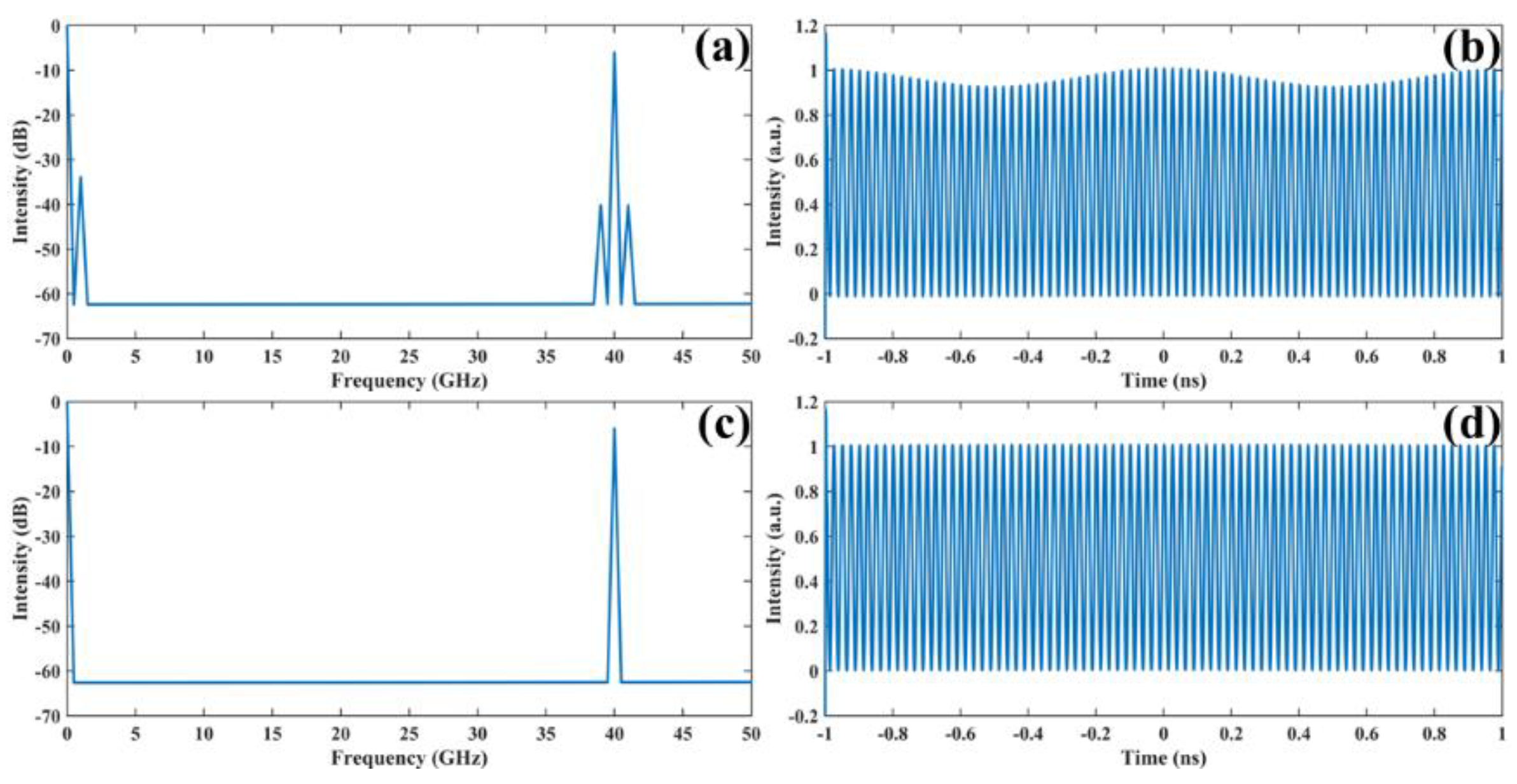
of 500 fs, and a C of 2 is used. In this case, the minimum length of the SMF can be estimated to be 5.35 km based on Equations (5) and (14). To make a comparison, a 4 km-long SMF was first used, which is shorter than the required minimum length of 5.38 km. For a desired frequency, such as
fc = 40 GHz, the time delay should be set to 21.123 ps.
Figure 2a,b show the RF spectrum and the time-domain waveform of the generated frequency, respectively. As shown in
Figure 2a, there are some harmonic components near the desired frequency
fc = 40 GHz. Correspondingly,
Figure 2b shows that a slow-varying oscillation of 1 GHz is clearly visible in the time domain, except for the 40 GHz fast oscillation. This indicates that unwanted components will be generated when the fiber length is shorter than the required minimum length, which is a situation that we should avoid in the experiment.
In order to obtain purer microwave signals without harmonic components, a roll of longer SMF with a length of 10 km was used to stretch the pulse. Under the circumstances, the time delay was set to 52.793 ps, so that the desired 40 GHz signal could be obtained. As shown in
Figure 2c, the RF spectrum indicates that the 40 GHz frequency is the only dominant frequency. Further, the comparison in
Figure 2b,d shows that there is no slow-varying oscillation in the time-domain waveform. Therefore, it is believed that a purer microwave signal can be generated by proper dispersion management.
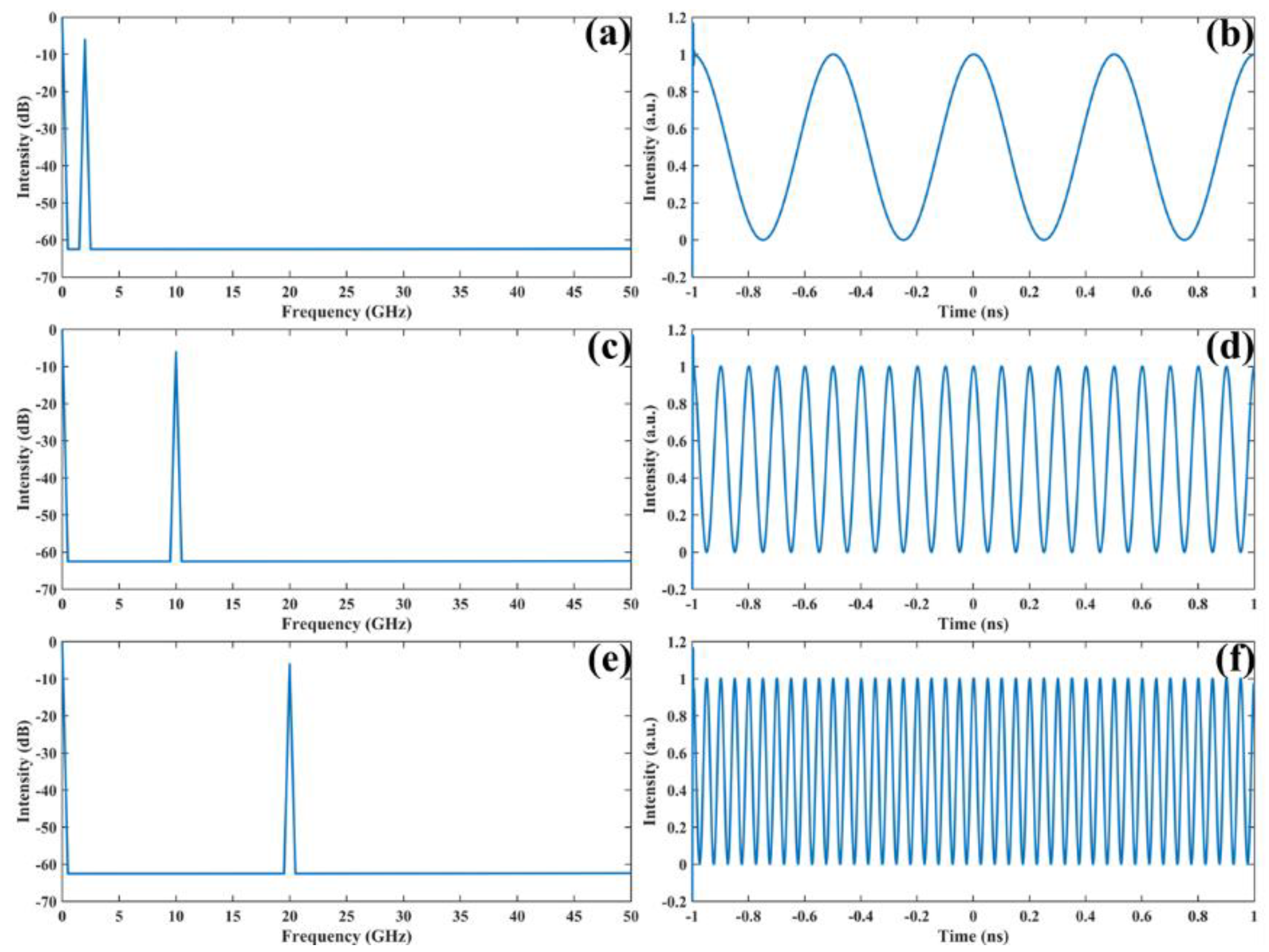
Furthermore, as shown in
Figure 3, the frequency tunability is verified. For a 10 km-long SMF with a fixed dispersion, the frequency tunability is demonstrated by simply tuning the time delay. A
fc of 2 GHz, 10 GHz, and 20 GHz could be obtained when the time delay was set to 2.64 ps, 13.20 ps, and 26.40 ps, respectively.
4. Experimental Results and Discussion
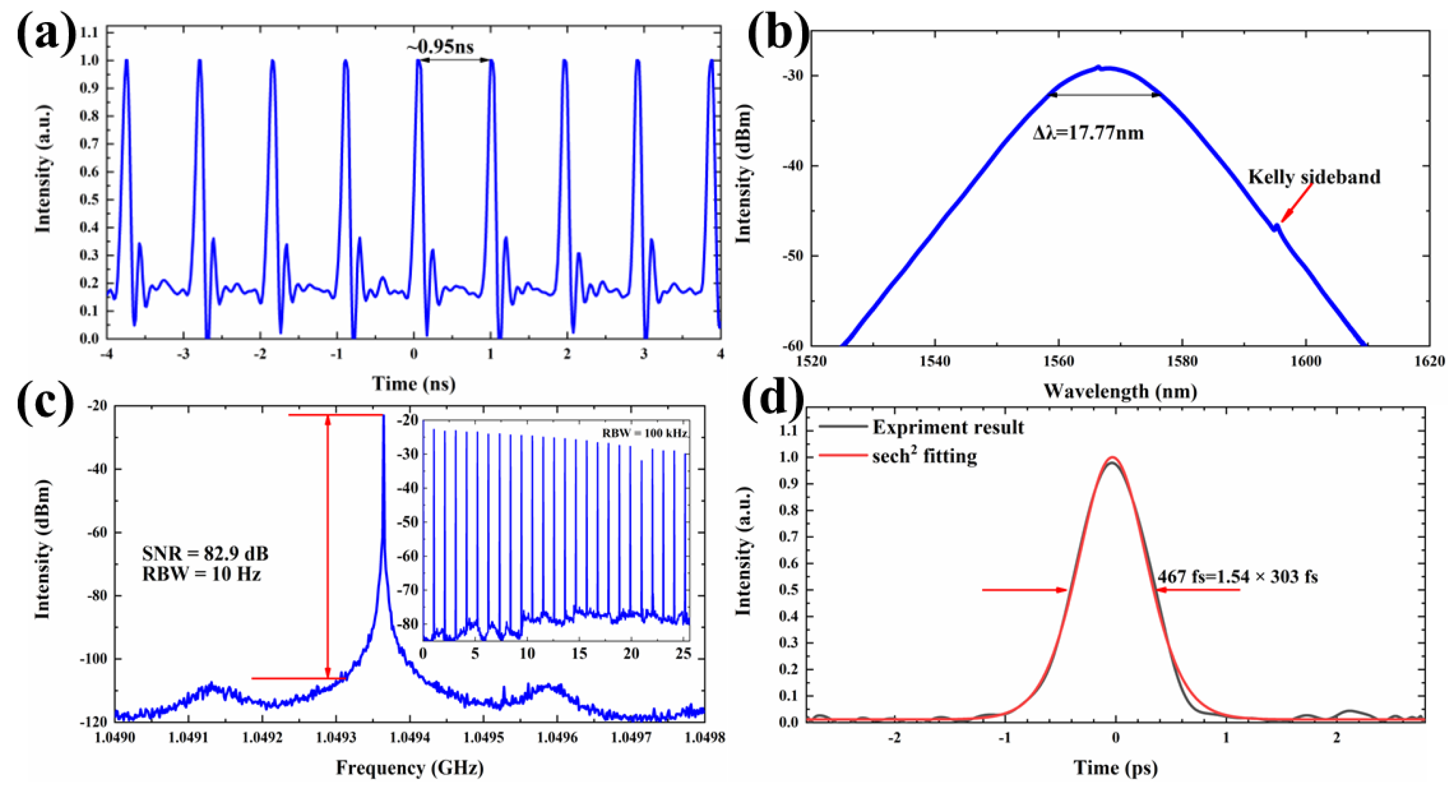
In this experiment, a self-made all-polarization-maintaining 1-GHz MLL was used, which had a compact structure. The laser realized self-started mode locking at a pump power of 280 mW. To offset some of the effects of fiber loss, the pump power was set to 800 mW with a 6.15 mW output power. In this case, the characteristics of the MLL are shown in
Figure 4.
Figure 4a shows the time-domain characteristics of the MLL, which delivered uniform pulse trains with a temporal period of about 0.95 ns.
Figure 4b illustrates the optical spectrum of the MLL with a typical Kelly sideband. The optical spectrum has a central wavelength of 1567.5 nm and a 3 dB spectral bandwidth of 17.7 nm, which is equivalent to a transform-limited pulse width of ~146 fs. As shown in
Figure 4c, the RF spectrum indicates a 1.049 GHz fundamental pulse repetition rate with a signal-to-noise ratio (SNR) of 82.9 dB, which matches with the temporal period of 0.95 ns in
Figure 4a. The resolution bandwidth (RBW) and span are 10 Hz and 800 kHz, respectively. The wide-range RF spectrum of the fundamental repetition rate and its harmonics in a span of 26.5 GHz (limited by the bandwidth of the RF signal analyzer) are depicted in the insert of
Figure 4c. The considerably high SNR and the clear intensity of the wide-range RF spectrum confirm that the laser is operating at a steady continuous-wave (CW) mode-locking state. As shown in
Figure 4d, the autocorrelation trace has a FWHM of 467 fs, corresponding to a
of 303 fs, when a sech
2 pulse shape is assumed with a deconvolution factor of 1.54. The pulse width is larger than the 146-fs transform-limited pulse width, which indicates that the pulses are slightly chirped. The optical spectrum of the mode-locked fiber laser was measured by an optical spectrum analyzer at a spectral resolution of 0.02 nm. The autocorrelation trace was measured by a commercial autocorrelator. The pulse train was detected by a high-speed photodetector and monitored by an oscilloscope. The RF spectrum was detected by the same high-speed photodetector and measured by a RF signal analyzer.
Based on the experimental setup shown in
Figure 1, we demonstrated the generation of 2–4 GHz microwave signals. The chirp parameter C could be calculated to 1.06, and
= 303 fs. Therefore, the required minimum length of PM-SMF is calculated to be 4.96 km based on the above theoretical analysis and discussion. In order to sufficiently stretch the pulse, a 10 km-long PM-SMF was used in this experiment. It is worth mentioning that the length of the fiber is fixed, so that tunable microwave signals could be obtained only by tuning the time delay Δ
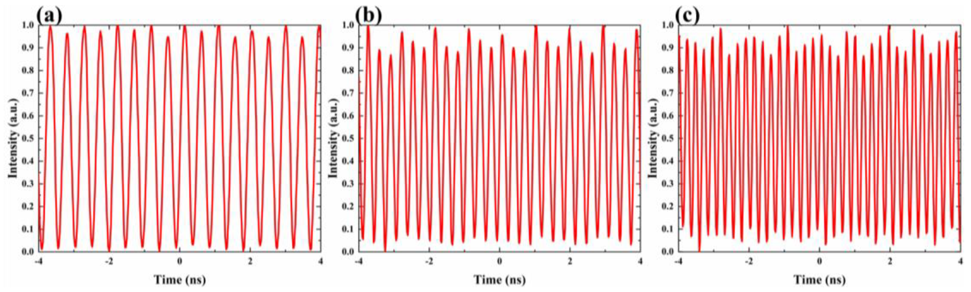
t. From Equations (9) and (10), the time delay could be assumed for a desired signal. For instance, 2–4 GHz microwave signals could be achieved when the time delay was set to 2.64 ps, 3.96 ps, and 5.28 ps by the computer-controlled TDL. Further, the time-domain waveforms of the 2–4 GHz generated microwave signals are shown in
Figure 5a–c.
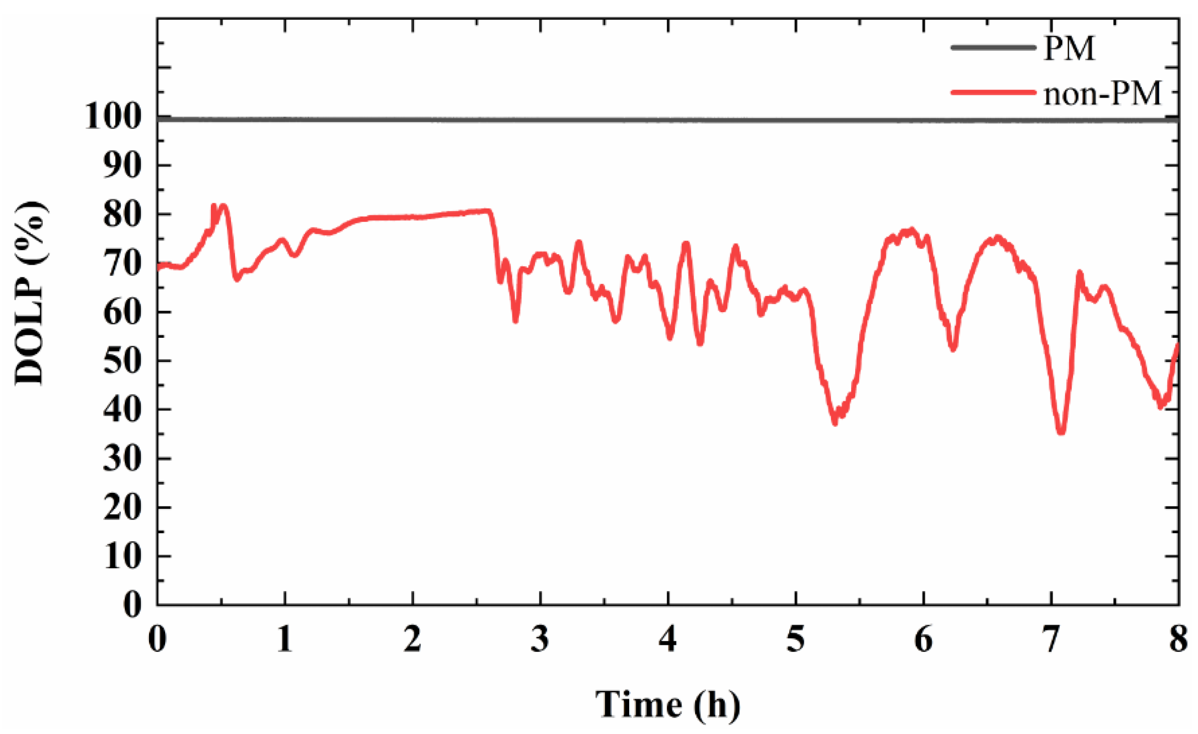
In addition, in order to prove the superior stability of the PM system, a long-term polarization test compared to a non-PM competitor is carried out after the MZI. The degree of linear polarization (DOLP) is defined as the ratio of the power of linearly polarized light to the total optical power in an optical signal. To make a comparison, the 8 h stability of the DOLP is measured for the non-PM and PM scheme, respectively. As shown in
Figure 6, the DOLP of the non-PM case is between 35% and 81% and is accompanied by great fluctuations. However, the DOLP of the PM case is always larger than 99%, which verifies that the PM system could meet with many polarization-related applications.
5. Discussion and Conclusions
In order to make a comparison, we summarized our work and previous similar works in
Table 1. As shown in
Table 1, this is the first work to show tunable microwave signal generation based on an all-PM 1-GHz passive MLL, so that there is no need for polarization controller. In addition, due to the devices used in this paper being almost all commercially available, the experiment in this paper has a high reproducibility. For example, the SESAM was produced by Batop GmbH, and other fiber-based devices can be found on commercial websites; the mode-locker used in Ref. [
13] is self-made.
In conclusion, we have theoretically and experimentally shown the generation of tunable microwave signals by the direct optical detection of chirped pulses and their delayed replicas. The numerical simulations show that by properly managing the dispersion in the system as well as the relative time delay of the MZI, one can tune the frequency of the generated microwave signal to any integer multiple of the fundamental repetition rate of the MLL. In the experiments, we demonstrated the generation of tunable microwave signals from 2–4 GHz based on an all-PM 1-GHz MLL. Due to the utilization of the polarization-maintaining devices, the stability of the system is further enhanced, and no additional polarization controller is needed. In addition, the output has a high DOLP of more than 99%. Moreover, a computer-controlled tunable delay line was used in this paper, which could provide a more accurate and automatic control of the time delay. It is believed that these demonstrations will further promote the development and application of photonics-based microwave generation in microwave photonics.


