Watermarking and Encryption for Holographic Communication


Abstract
:1. Introduction
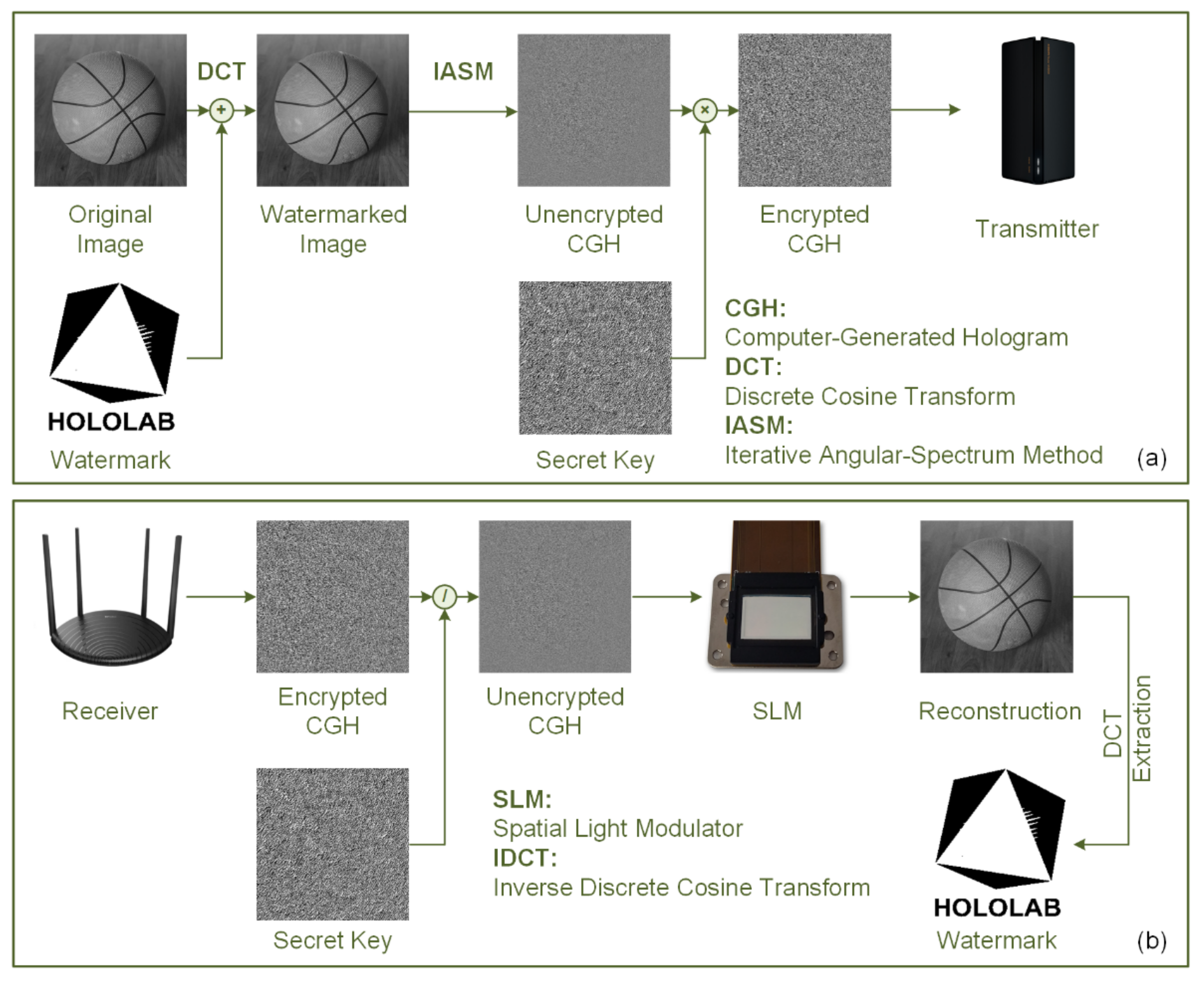
2. Methods
2.1. Insertion of the Watermark
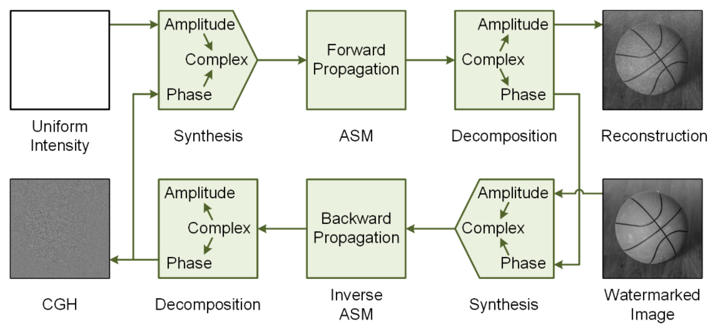
2.2. Calculation of the CGH
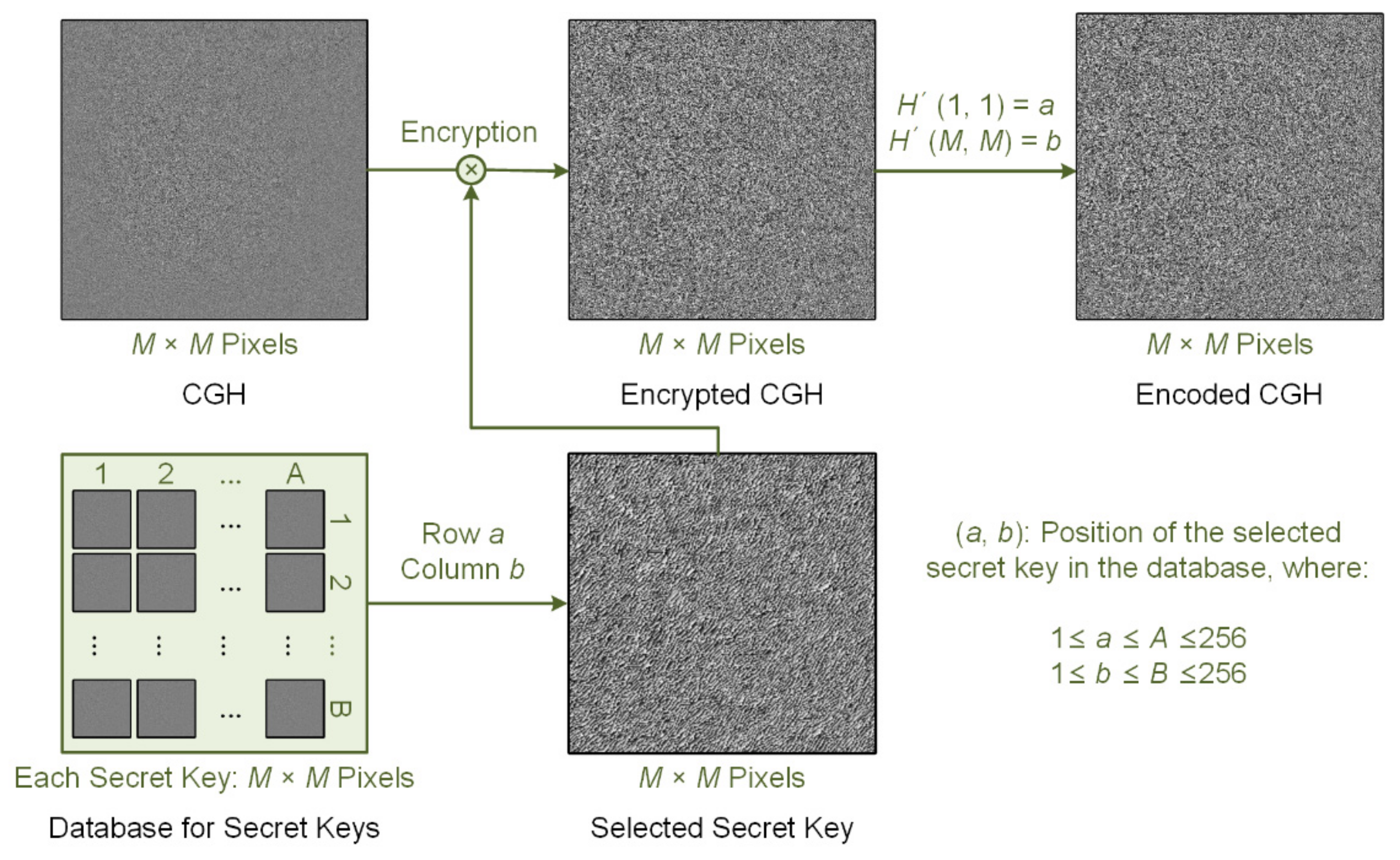
2.3. Encryption of the CGH
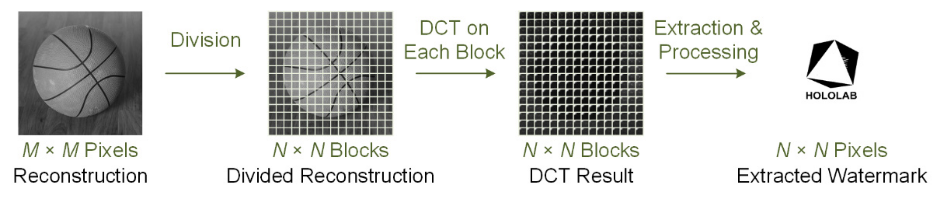
2.4. Reconstruction of the CGH
3. Results
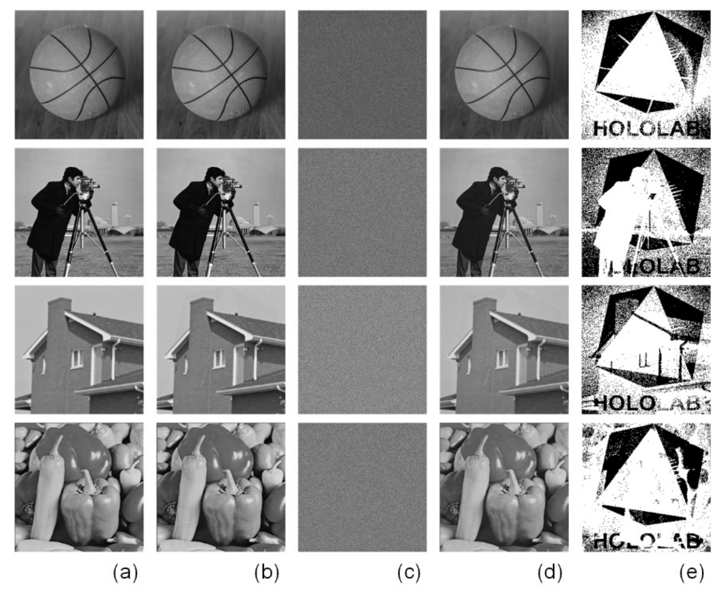
3.1. Numerical Experiments
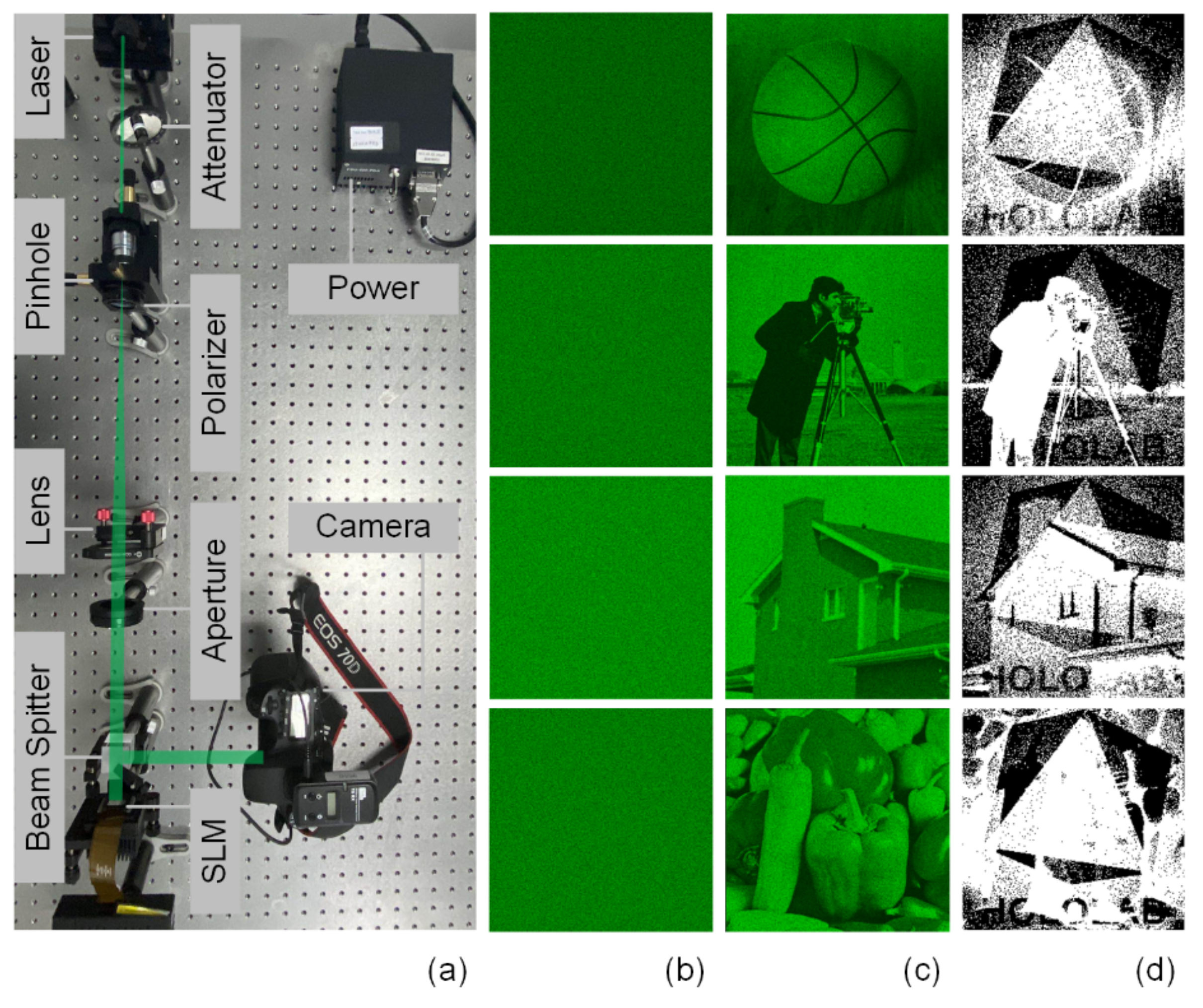
3.2. Optical Experiments
4. Discussion
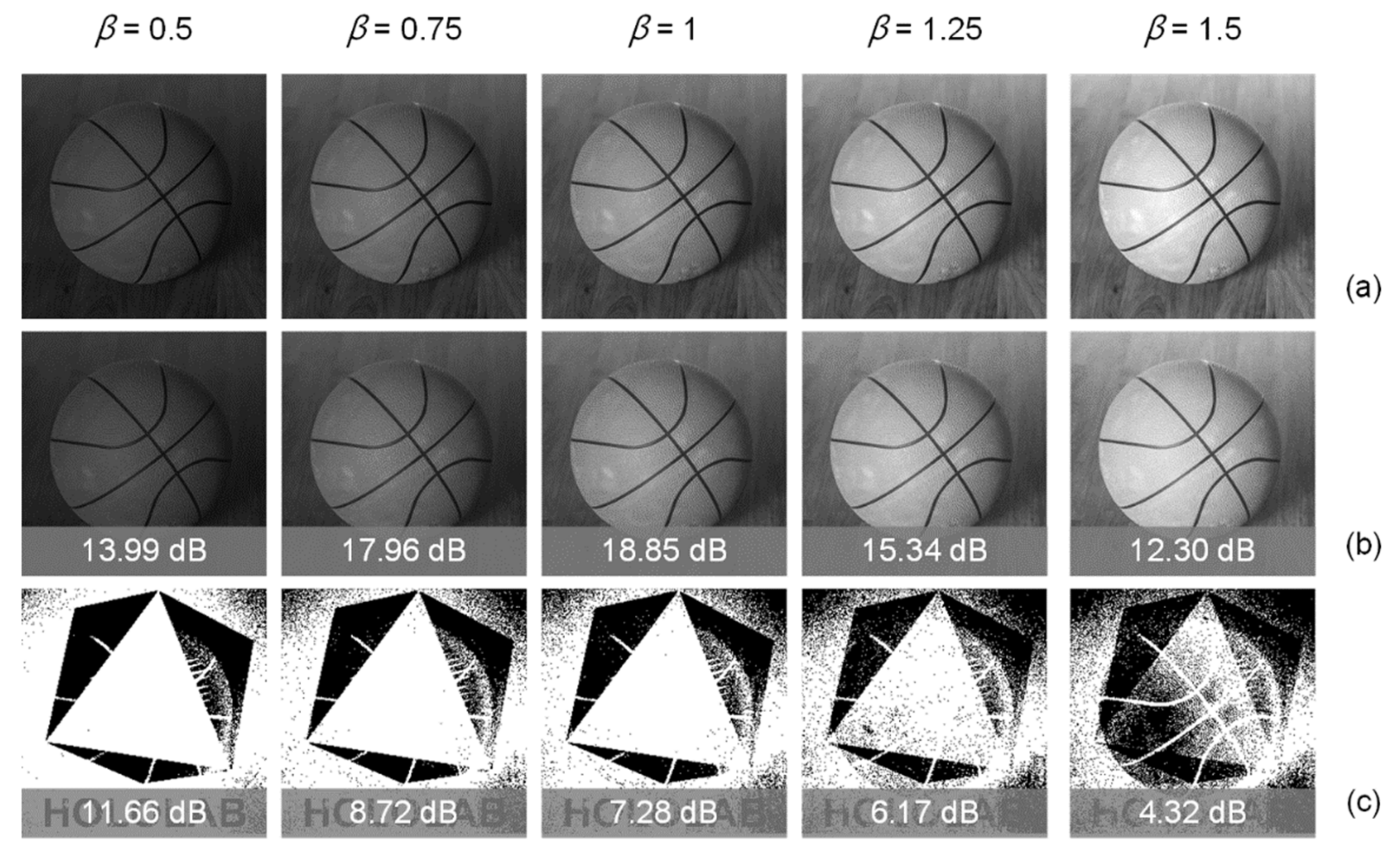
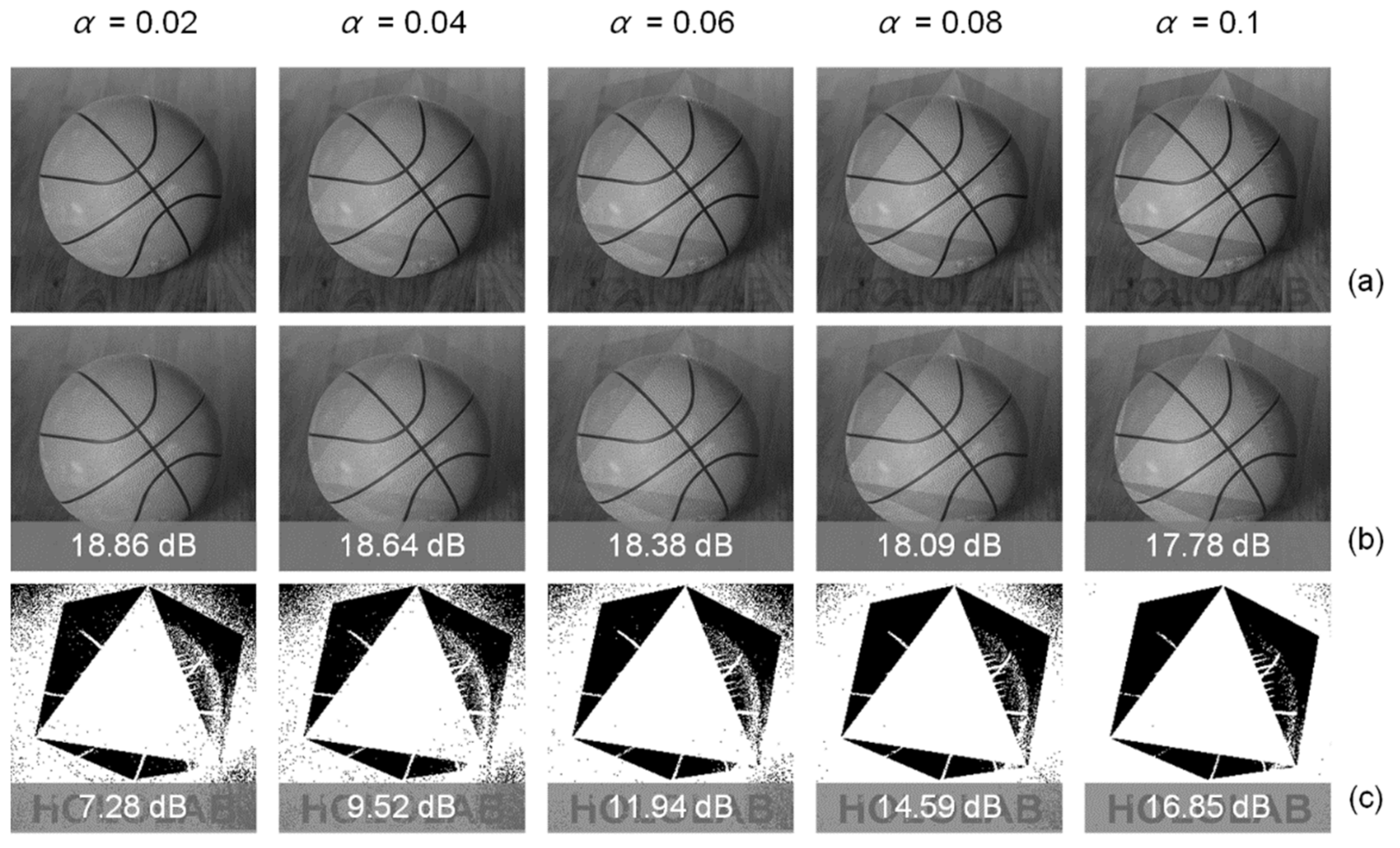
4.1. Effect of Scale Factors
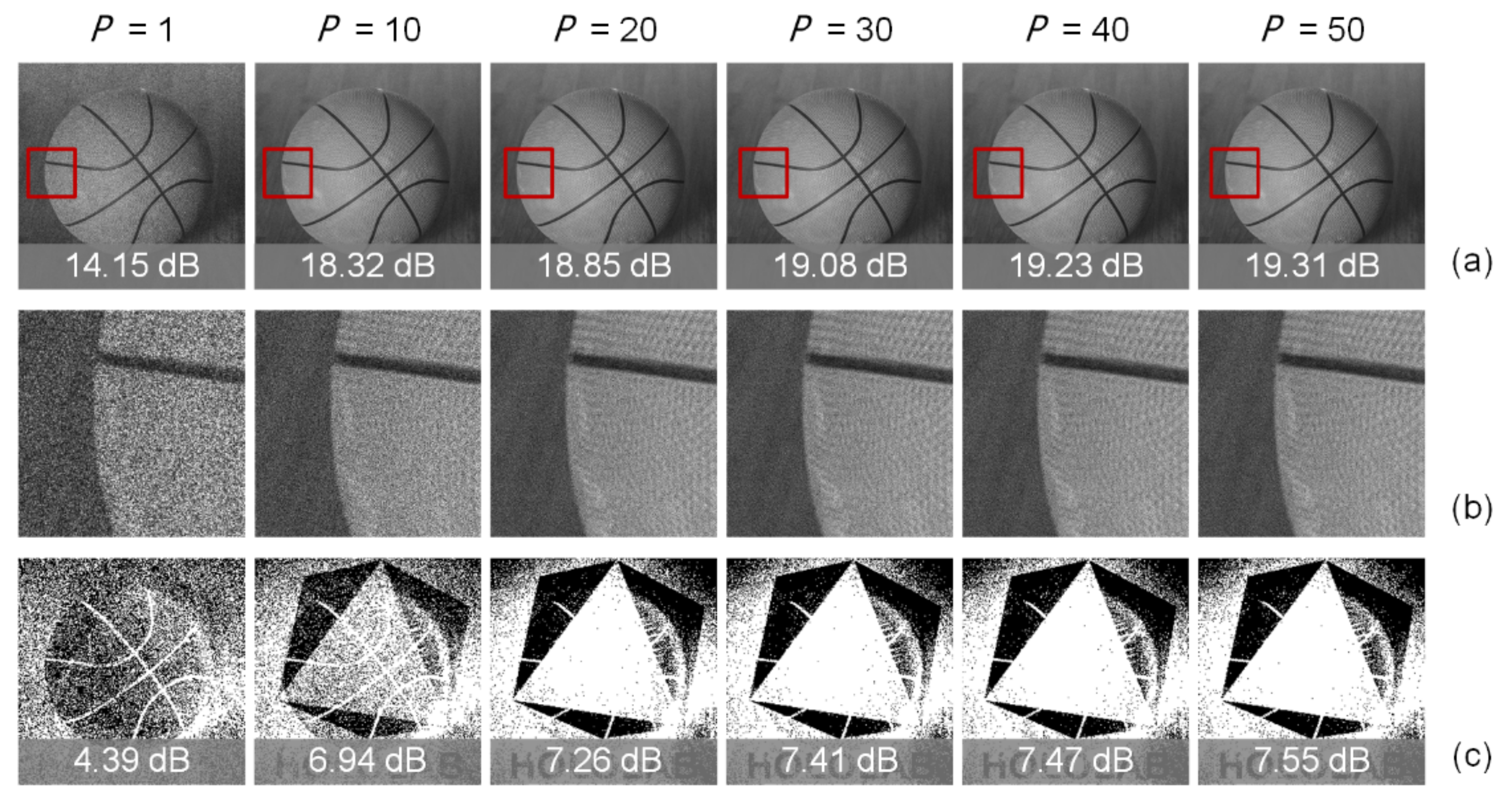
4.2. Effect of Iteration-Based Optimization
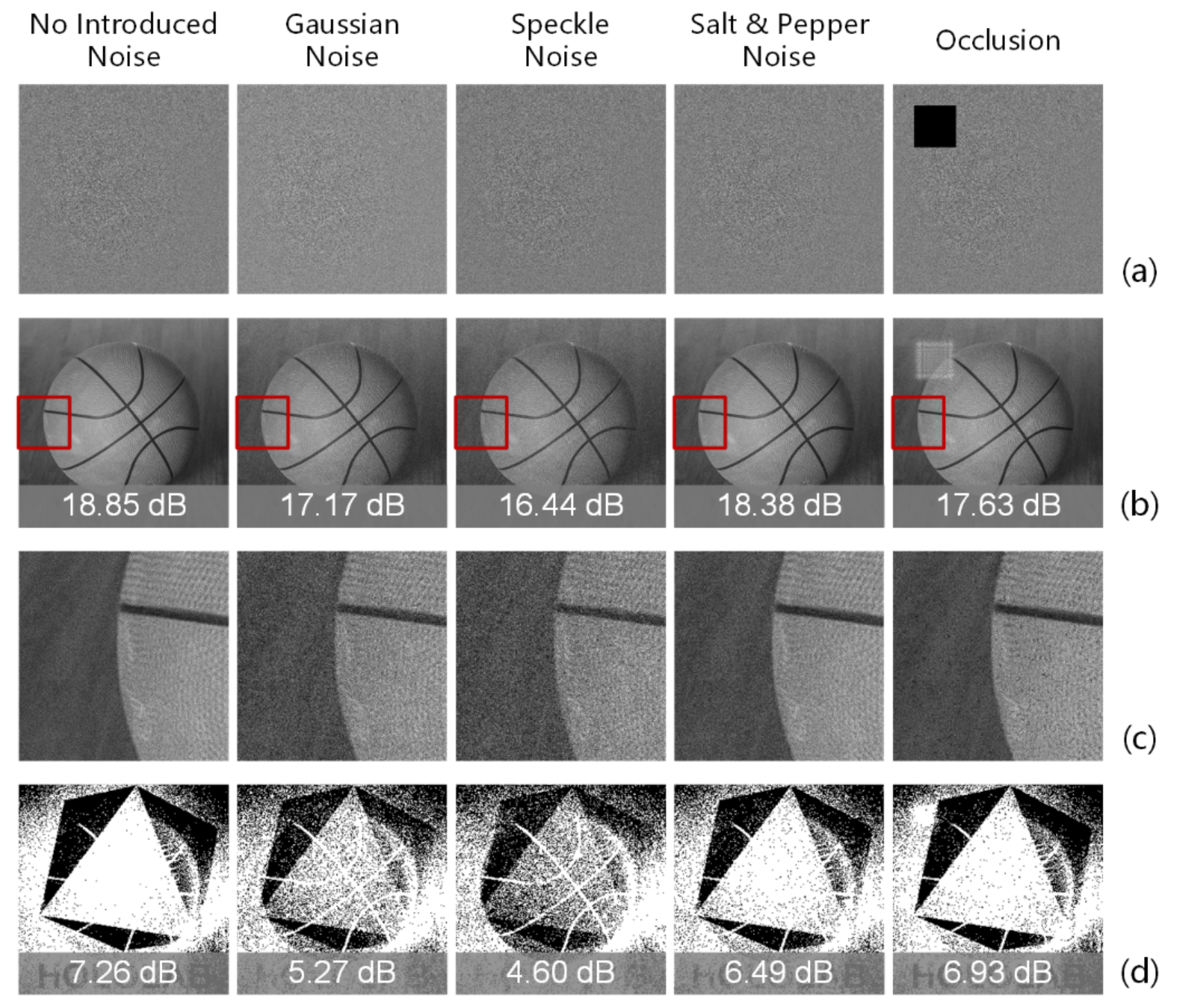
4.3. Robustness
5. Conclusions
Author Contributions
Funding
Institutional Review Board Statement
Informed Consent Statement
Data Availability Statement
Conflicts of Interest
References
- Orts-Escolano, S.; Rhemann, C.; Fanello, S.; Chang, W.; Kowdle, A.; Degtyarev, Y.; Kim, D.; Davidson, P.L.; Khamis, S.; Dou, M.; et al. Holoportation: Virtual 3D Teleportation in Real-Time. In Proceedings of the 29th Annual Symposium on User Interface Software and Technology, Tokyo, Japan, 16–19 October 2016. [Google Scholar]
- Gotsch, D.; Zhang, X.; Merritt, T.; Vertegaal, R. TeleHuman2: A Cylindrical Light Field Teleconferencing System for Life-Size 3D human Telepresence. In Proceedings of the 2018 CHI Conference on Human Factors in Computing System, Montreal, QC, Canada, 21–26 April 2018. [Google Scholar]
- Lawrence, J.; Goldman, D.B.; Achar, S.; Blascovich, G.M.; Desloge, J.G.; Fortes, T.; Gomez, E.M.; Häberling, S.; Hoppe, H.; Huibers, A.; et al. Project Starline: A high-fidelity telepresence system. ACM Trans. Graph. 2021, 40, 242. [Google Scholar] [CrossRef]
- He, Z.; Sui, X.; Jin, G.; Cao, L. Progress in virtual reality and augmented reality based on holographic display. Appl. Opt. 2019, 58, A74–A81. [Google Scholar] [CrossRef] [PubMed]
- He, Z.; Sui, X.; Cao, L. Holographic 3D display using depth maps generated by 2D-to-3D rendering approach. Appl. Sci. 2021, 11, 9889. [Google Scholar] [CrossRef]
- He, Z.; Sui, X.; Zhang, H.; Jin, G.; Cao, L. Frequency-based optimized random phase for computer-generated holographic display. Appl. Opt. 2021, 60, A145–A154. [Google Scholar] [CrossRef]
- Liu, K.; He, Z.; Cao, L. Pattern-adaptive error diffusion algorithm for improved phase-only hologram generation. Chin. Opt. Lett. 2021, 19, 050501. [Google Scholar] [CrossRef]
- He, Z.; Sui, X.; Jin, G.; Cao, L. Distortion-correction method based on angular spectrum algorithm for holographic display. IEEE Trans. Ind. Inform. 2019, 15, 6162–6169. [Google Scholar] [CrossRef]
- Refregier, P.; Javidi, B. Optical image encryption based on input plane and Fourier plane random encoding. Opt. Lett. 1995, 20, 767–769. [Google Scholar] [CrossRef]
- Zhang, Y.; Wang, B. Optical image encryption based on interference. Opt. Lett. 2008, 33, 2443–2445. [Google Scholar] [CrossRef]
- Tsang, P.W.M.; Poon, T.C.; Cheung, K.W.K. Fast numerical generation and encryption of computer-generated Fresnel holograms. Appl. Opt. 2011, 50, 46–52. [Google Scholar] [CrossRef]
- Wang, X.; Zhao, D. Optical image hiding with silhouette removal based on the optical interference principle. Appl. Opt. 2012, 51, 686–691. [Google Scholar] [CrossRef]
- Chen, W.; Chen, X. Security-enhanced interference-based optical image encryption. Opt. Commun. 2013, 286, 123–129. [Google Scholar] [CrossRef]
- Cai, J.; Shen, X.; Lei, M.; Lin, C.; Dou, S. Asymmetric optical cryptosystem based on coherent superposition and equal modulus decomposition. Opt. Lett. 2015, 40, 475–478. [Google Scholar] [CrossRef]
- Kong, D.; Cao, L.; Jin, G.; Javidi, B. Three-dimensional scene encryption and display based on computer-generated holograms. Appl. Opt. 2016, 55, 8296–8300. [Google Scholar] [CrossRef]
- Kong, D.; Cao, L.; Shen, X.; Zhang, H.; Jin, G. Image encryption based on interleaved computer-generated holograms. IEEE Trans. Ind. Inform. 2018, 14, 673–678. [Google Scholar] [CrossRef]
- Barni, M.; Bartolini, F.; Piva, A. Improved wavelet-based watermarking through pixel-wise masking. IEEE Trans. Image Process. 2001, 10, 783–791. [Google Scholar] [CrossRef]
- Agreste, S.; Puccio, L. Wavelet-based watermarking algorithms: Theory, applications and critical aspects. Int. J. Comput. Math. 2011, 88, 1885–1895. [Google Scholar] [CrossRef]
- Horng, S.-J.; Rosiyadi, D.; Fan, P.; Wang, X.; Khan, M.K. An adaptive watermarking scheme for e-government document images. Multimed. Tools Appl. 2014, 72, 3085–3103. [Google Scholar] [CrossRef]
- Wang, C.-Y.; Kong, X.-W.; Li, C. Process color watermarking: The use of visual masking and dot gain correction. Multimed. Tools Appl. 2017, 76, 16291–16314. [Google Scholar]
- Liu, J.; Rao, Y.; Huang, Y. Complex wavelet-based image watermarking with the human visual saliency model. Electronics 2019, 8, 1462. [Google Scholar] [CrossRef]
- Kumari, R.; Mustafi, A. An optimized framework for digital watermarking based on multi-parameterized 2D-FrFT using PSO. Optik 2021, 248, 168077. [Google Scholar] [CrossRef]
- He, Z.; Sui, X.; Jin, G.; Chu, D.; Cao, L. Optimal quantization for amplitude and phase in computer-generated holography. Optics Express 2021, 29, 119–133. [Google Scholar] [CrossRef]
- Hamidi, M.; Haziti, M.E.; Cherifi, H.; Hassouni, M.E. Hybrid blind robust image watermarking technique based on DFT-DCT and Arnold transform. Multimed. Tools Appl. 2018, 77, 27181–27214. [Google Scholar] [CrossRef]
- Ernawan, F.; Kabir, M.N. A robust image watermarking technique with an optimal DCT-psychovisual threshold. IEEE Access 2018, 6, 20464–20480. [Google Scholar] [CrossRef]
- Sun, P.; Chang, S.; Liu, S.; Tao, X.; Wang, C.; Zheng, Z. Holographic near-eye display system based on double-convergence light Gerchberg-Saxton algorithm. Opt. Express 2018, 26, 10140–10151. [Google Scholar] [CrossRef]
- Kim, H.; Kim, M.; Lee, W.; Ahn, J. Gerchberg-Saxton algorithm for fast and efficient atom rearrangement in optical tweezer traps. Opt. Express 2019, 27, 2184–2196. [Google Scholar] [CrossRef]
- Wu, Y.; Wang, J.; Chen, C.; Liu, C.-J.; Jin, F.-M.; Chen, N. Adaptive weighted Gerchberg-Saxton algorithm for generation of phase-only hologram with artifacts suppression. Opt. Express 2021, 29, 1412–1427. [Google Scholar] [CrossRef]
- Li, R.; Gao, Y.; Cao, L. In situ calibration for a phase-only spatial light modulator based on digital holography. Opt. Eng. 2020, 59, 053101. [Google Scholar] [CrossRef]


Publisher’s Note: MDPI stays neutral with regard to jurisdictional claims in published maps and institutional affiliations. |
© 2022 by the authors. Licensee MDPI, Basel, Switzerland. This article is an open access article distributed under the terms and conditions of the Creative Commons Attribution (CC BY) license (https://creativecommons.org/licenses/by/4.0/).
Share and Cite
He, Z.; Liu, K.; Cao, L. Watermarking and Encryption for Holographic Communication. Photonics 2022, 9, 675. https://doi.org/10.3390/photonics9100675
He Z, Liu K, Cao L. Watermarking and Encryption for Holographic Communication. Photonics. 2022; 9(10):675. https://doi.org/10.3390/photonics9100675
Chicago/Turabian StyleHe, Zehao, Kexuan Liu, and Liangcai Cao. 2022. "Watermarking and Encryption for Holographic Communication" Photonics 9, no. 10: 675. https://doi.org/10.3390/photonics9100675