1. Introduction
Distributed Raman amplifier (DRA) is an important amplification scheme for optical communication systems due to its low noise figure (NF) and wideband flexible gain [
1,
2]. In order to enhance the performance of DRAs, many methods have been applied in DRAs for achieving lower noise by improving Raman pumping scheme. The most common used is backward pumping, which shows reduced penalty on relative intensity noise (RIN) compared to forward pumping [
3]. High order pumping can also enhance RIN performance [
4,
5]. RIN is transferred from pump lasers to DRAs and for high order pumping scheme, RIN can be effectively reduced because of multiple transfers from high order pump to signals [
6]. Another practical scheme is random fiber laser structure, which utilizes high order pumps to generate first order random fiber laser with the fiber Rayleigh backscattering and fiber Bragg grating as reflectors [
7,
8]. However, random fiber laser structure is essentially bi-directional pumping, consequently offering relatively high RIN [
9]. But the experiment demonstrated that this scheme can provide better balance between amplified spontaneous emission (ASE) noise and nonlinear effects, which results in better transmission performance [
10,
11,
12]. In addition to them, it is shown in recent studies that DRAs using broadband optical pump exhibit superior RIN performance over conventional DRAs including backward pumping and random fiber laser [
13]. The broadband optical pump is generated by ASE of second order pump in the fiber with high Raman gain coefficient, and then the broadband optical pump is launched into transmission fiber to amplify the signal. It is demonstrated that although the broadband pump has the similar RIN to the semiconductor laser, the RIN of amplified signal with broadband pump is mitigated compared to low RIN laser pumping and pumping schemes mentioned above [
14].
On the other hand, flat gain of amplifiers is usually demanded to achieve great transmission performance. For broader applications, arbitrary gain spectrum would be of great significance since different transmission spectrum will be needed varied with different systems and different circumstances. For example, Erbium-doped fiber amplifiers (EDFAs) are always utilized together with other amplifiers to build up a hybrid amplifier with large gain and low noise [
15,
16]. Then, the gain spectrum of that amplifier needs to be shaped to compensate the gain fluctuation of EDFA so as to achieve flat gain for the hybrid amplifier [
17]. Arbitrary gain spectrum shaping with high precision and even dynamic operation is thus highly desired. Stimulated Raman scattering is only related to the power and frequency difference between two lights, so DRAs are able to realize flexible gain spectrum including bandwidth and profile by combining multiple pump lasers working in different wavelengths and powers [
18]. Previous studies have focused on flat gain and tilted gain with 2 to 8 pumps or more [
19]. Only 4 or more pumps can provide acceptable results which well fit the target of design, and the precision is highly limited by the number of pumps. Moreover, many specially customized pump lasers will also make it difficult in experiments and transmission systems. With the broadband pump arbitrarily shaped by waveshaper with frequency resolution up to 1GHz, it can be regarded as multiple pumps (depending on bandwidth and resolution) to achieve an ultrafine and arbitrary gain spectrum.
Optimizing shapes of pump spectrum that can realize desired gain spectrum is another challenging problem, which revolves multiple parameters. The most conventional optimization algorithm is genetic algorithm (GA). However, GA needs many iterations for complex crossover, mutation and selection to converge to the optimal solution in parameter space, and it consumes long time. If the target is changed, all optimization processes must be repeated from the beginning again. Moreover, with the number of parameters increasing, the complexity of GA increases rapidly and the optimal solution might be difficult to converge [
20]. Recent research shows neural networks (NN) based inverse design is a considerable scheme for DRAs [
21,
22,
23]. The NN can be trained as a regression of parameters
K and results
G, whose input is results
G and parameters
K. In another way, well-trained NN can be regarded as an inverse mapping
. The advantage of this inverse structure is that the parameters corresponding to target can be directly calculated by inputting target into trained NN. If data set used for training is collected properly and extensively, the trained NN can be universal, which means when the target changed, desired parameters can also be directly calculated without retraining. Compared to GA, another advantage of NN is the tolerance to the number of parameters. NN has the capacity of handling the optimization of more parameters and solving a mapping with more complexity by deepening networks.
Recent publication proposed a scheme of inverse NN, in which they utilized regression NN to predict flat and titled gain profile of DRAs. However, the performance of this NN might not meet an acceptable expection, therefore a fine-tuning phase is applied to further optimization [
23]. This fine-tuning phase requires a trained NN as the direct mapping
, and the output of the inverse NN will be further optimized with this direct NN by gradient-descent algorithm. The optimization results show promising improvement on backward pumping DRAs over C and C+L band, achieving maximum error below 0.5 dB for C band and 1 dB for C+L band. However, this scheme requires training for two NNs and iterations of gradient-descent algorithm, which would be quite time-consuming.
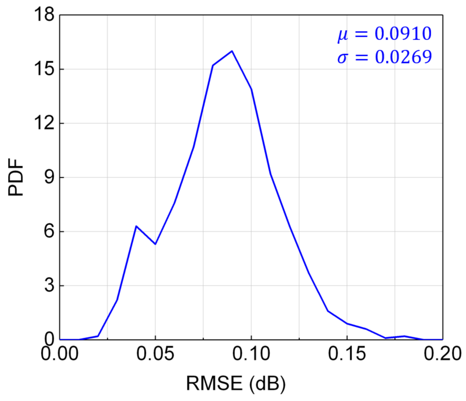
In this paper, a new approach by machine learning for inverse design of DRA with broadband pump is proposed for achieving ultrafine, dynamic and arbitrary gain spectrum. The ASE source can be considered as multiple discrete pumps with power levels dynamically tunable which is typically achieved by passing the ASE source through a waveshaper filter. We promote the performance of NN by employing classification NN instead of regression NN. Finally, we realize maximum gain flatness of 0.1086 dB for flat gain spectrum. The probability density functions (PDF) of root mean square error (RMSE) and are presented for arbitrary gain spectrum, realizing mean of 0.0910 dB, 0.1956 dB and standard deviation of 0.0269 dB, 0.0817 dB for RMSE and , respectively. We also find the best match between the bands of pump and signal. Owing to programmability of waveshaper, dynamic Raman gain spectrum can be realized and has the potential to compensate the gain distortion caused by other devices in real time.
2. Broadband Pump Based DRA and Inverse Design
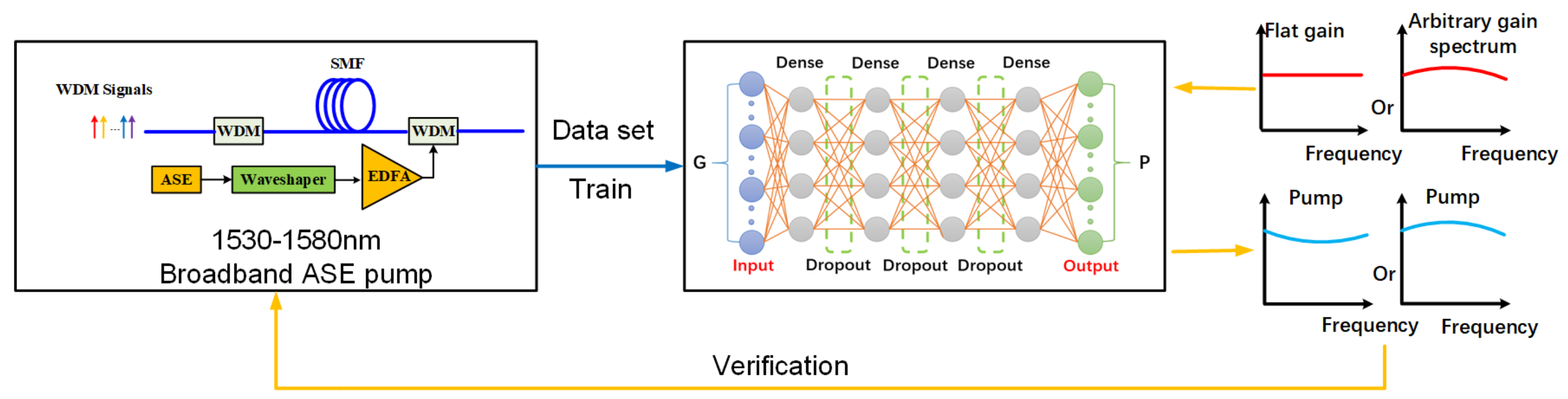
Figure 1 shows the procedure of inverse design for ultrafine and arbitrary waveshaping of gain spectrum. Data set is obtained by numerical simulation of the configuration, and then employed to train our inverse NN, whose input is gain spectrum
and output is pump spectrum
. Once the NN has been well trained, it can be recognized as the mapping between gain spectrum and pump spectrum. Different target profiles of gain spectra are input to the trained NN for attaining corresponding pump spectrum. Nevertheless, trained NN only guarantees the reliability within training set. In order to validate the universal reliability of this inverse design, the targets of gain spectra out of training set are input into NN and the attained pump spectra need go through the numerical simulation of configuration to calculate actual gain spectrum, which will be compared with target gain spectrum to measure the accuracy of NN.
2.1. Data Set Generation
The configuration of DRA with broadband pump is presented in
Figure 2. The ASE source generates the broadband pump, which can be realized by ASE of EDFAs, so the band is set to 1530–1580 nm. Considering the power of the ASE is generally not high enough and the waveshaper does not support very high power, the ASE is firstly input into waveshaper and then the shaped ASE is launched into EDFA to acquire sufficient power. The waveshaper supports C band and its frequency setting resolution is 1 GHz. We can write the files to control attenuation spectrum of waveshaper through software, realizing arbitrary shaped ASE. Moreover, considering EDFA does not flatly amplify the shaped ASE, the attenuation spectrum of waveshaper should be adjusted to compensate the error caused by EDFA. The pump obtained from inverse design corresponds to the pump fed into transmission fiber. In order to reduce the RIN of this DRA, the shaped broadband pump is utilized as backward pump. The band of signals is 1655–1685 nm according the band of pump. The selection of signals band will be illustrated in Part III. The transmission fiber is 70 km EX2000 single-mode fiber fabricated by Corning, whose loss of pump is 0.15 dB/km and loss of signal is 0.277 dB/km. The parameters used are shown in
Table 1.
For a backward pumping single-mode DRA with
signals and
pumps, signal power evolution is described by following non-linear ordinary differential equations [
24]:
where “+” “−” denote the direction of pumps and signals,
is the optical power at frequency
,
is attenuation at frequency
,
is Raman gain coefficient between frequencies
and
,
is polarization correlation coefficient and the value is usually 2,
is effective mode field area of SMF.
Raman on-off gain is defined as:
where
.
In our DRA with broadband pump, the broadband pump and the signal are divided into 40 discrete wavelengths, respectively ( = 40, = 40). The power of each signal channel is 0 dBm and the total power of signal is 6 dBm. The pump spectra are randomly generated with the power of each wavelength ranging from 0 to 8 mW. Then, gain spectra are calculated by solving the Equations (1) and (2) with the randomly generated pump spectra . The gain spectra and the pump spectra finally compose the data set utilized to train NN. The scale of data set should be selected carefully, because too large scale will demand more computing resources, leading to increased time consumption. Data set of too small scale contains insufficient information, thus reducing the accuracy of the trained NN. The scale of our data set is 5000. Finally, the data should be normalized before training.
2.2. Establishment of NN
The establishment of NN is the key procedure of our inverse design because it directly determines the performance of mapping between gain and pump spectra. Considering physical equation characteristics, we select deep NN with dense layers to fit the mapping between pump and gain. The scale of NN, measured by number of layers and neurons, should be carefully designed according to the complexity of the mapping. Too small scale of NN has insufficient capacity of learning the complex mapping and too large scale of NN will bring many drawbacks, such as demand of large data set, poor convergence and more time consumption. Moreover, too large scale of NN will induce overfitting, which leads to the excellent performance on training set but poor generalization. As illustrated in
Figure 1, based on experience, our NN contains for hidden layers with 500 neurons in each hidden layer. However, this scale of NN remains overfitting, so Dropout layers are applied between every two hidden layers. Dropout can effectively alleviate the occurrence of overfitting and achieve regularization to a certain extent, which contributes to accuracy of prediction. The ratio selection ranges 0.05 to 0.2 according to experience. In our work, Dropout ratio is 0.1 in all layers. Function ReLU is the most common used activation function in neutral networks and it is also utilized in first three hidden layers in our NN. The activation function of the last hidden layer is Sigmoid function, which maps the vectors to (0, 1).
The loss function is another factor significantly determining the accuracy of NN. Essentially, our inverse design is a regression problem to obtain the appropriate mapping between gain and pump. Traditional NNs for regression usually utilize mean square error (MSE) or RMSE as loss function, which is respectively defined as:
MSE and RMSE are usually used to measure the distance of two vectors, so the error between NN’s output vectors and label vectors can be measured by MSE and RMSE. However, in our scheme, we employ binary cross entropy (BCE) [
25] as loss function. BCE is defined as:
Compared with MSE, BCE is more sensitive to the fine fluctuation. We respectively demonstrate the comparison between MSE and BCE by their performance.
2.3. Validation
Once the training of NN completed, NN can be seen as the mapping between gain spectrum and pump. However, the training result only indicates the accuracy on training set, so the accuracy of NN on the data out of training set must be validated additionally. Flat gain spectra and arbitrary gain spectra not included in training set are input into NN to obtain pumps, which are then input into equation solver to calculate the actual gain spectrum. For flat gain spectrum, we use gain flatness to measure the accuracy of NN. Gain flatness is defined as:
For arbitrary gain spectrum, we use RMSE to measure the accuracy of NN.
3. Result and Discussion
First, we present the performance comparison of MSE and BCE with the optimization target of arbitrary gain spectra.
Figure 3 shows the results of 3 gain spectra and each RMSE as error between target and actual gain spectrum is calculated. The RMSE of BCE loss function is 0.037, 0.047 and 0.052, respectively. The RMSE of MSE loss function is 0.103, 0.128 and 0.199, respectively. The result shows that BCE loss function is superior to MSE loss function in our optimization. Therefore, we utilize BCE as loss function and the following results are all obtained with BCE.
Figure 4 presents the results of gain spectra. In
Figure 4a, we demonstrate 6 groups of target and actual gain spectrum at the on-off gain level of 7.5 dB, 8.5 dB, 9.5 dB, 10.5 dB, 11 dB and 11.5 dB, respectively. It can be observed that curves of each group fit very well with high accuracy. The gain flatness of actual gain spectra at different on-off gain are presented in
Figure 4b and the maximum of gain flatness is 0.1086 dB.
Our scheme also has a strong ability to realize arbitrary gain spectrum.
Figure 5 shows that we give the optimization results of four kinds of gain spectrum shapes and they also fit the target curve very well. The RMSE of each group are calculated and they are 0.062 dB, 0.074 dB, 0.040 dB and 0.026 dB, respectively. In order to further illustrate the university of our scheme for arbitrary gain spectrum, we calculated the PDF of RMSE and
, respectively, which is obtained by thousands of optimization results with random target gain spectrum.
Figure 6 shows the PDF of RMSE, whose mean and standard deviation is 0.0910 dB and 0.0269 dB, respectively. The maximum RMSE is less than 0.2 dB. Particularly, the probability for RMSE ≤ 0.13 dB is 96.6%.
Figure 7 shows the PDF of
, whose mean and standard deviation is 0.1956 dB and 0.0817 dB, respectively. It can be observed that the maximum of
is less than 0.65 dB and the probability for
≤ 0.34 dB is 95.9%.
The band of signals and pump must match to obtain the excellent result. From the optimization procedure, we find the relationship between the band of signal and pump to be as
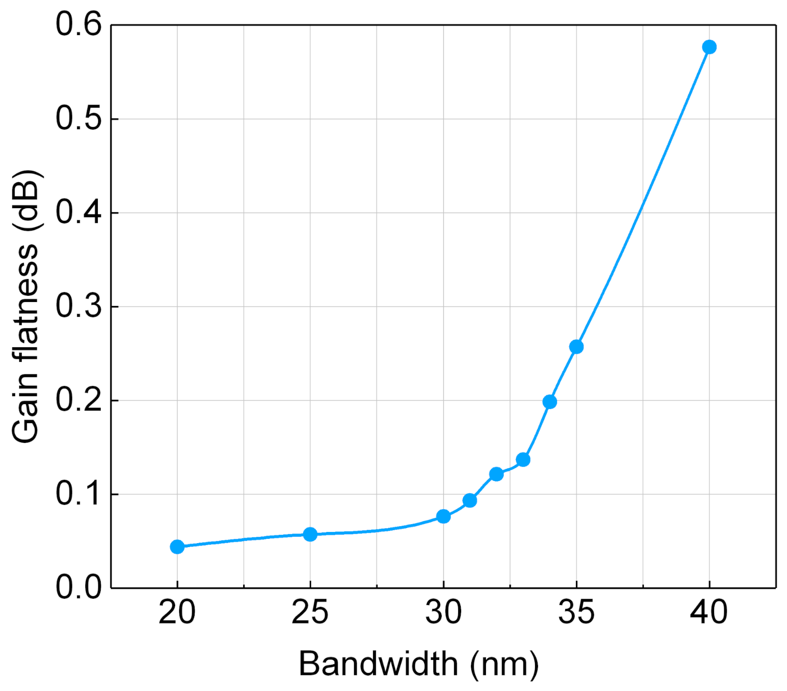
Figure 8 shows. The peak of the Raman gain locates at the 13.1 THz frequency shift of the pump, and the band of gain shifted from broadband pump must cover the band of signal. We speculate that if the gain band could not cover the signal, the signal at edge of the band could not get enough gain, therefor difficult to control. In order to prove our conjecture, we demonstrate the configurations where the band of pump is fixed and different bandwidth of signal centered at 1670 nm are applied. The gain flatness of each configuration at 10 dB on-off gain is used to measure the accuracy of optimization. The result is presented in
Figure 9. For the bandwidth of signal less than 30 nm, optimization has a high accuracy of less than 0.1 dB gain flatness. When the bandwidth of signal increases to more than 30 nm, the gain flatness increases rapidly. The result reveals that the gain band of broadband pump must cover the band of signal and their difference must be greater than a certain threshold.
During the process of optimization, we also found the reason of poor result with small probability as
Figure 6 and
Figure 7 shows. The broadband pump can be regarded as the superposition of multiple pumps with different wavelength. However, the Raman gain spectrum of Silica fiber in reference [
26] shows that a 3 THz platform of maximum gain exists and 3 dB bandwidth is about 7 THz, which means that no matter how these pumps with different wavelength are combined, the curve of gain spectrum is impossible to be sharper than the Raman spectrum. So, for some spectra with extremely sharp curve, the result does not fix very well, but
Figure 7 shows the maximum
less than 0.65 dB.
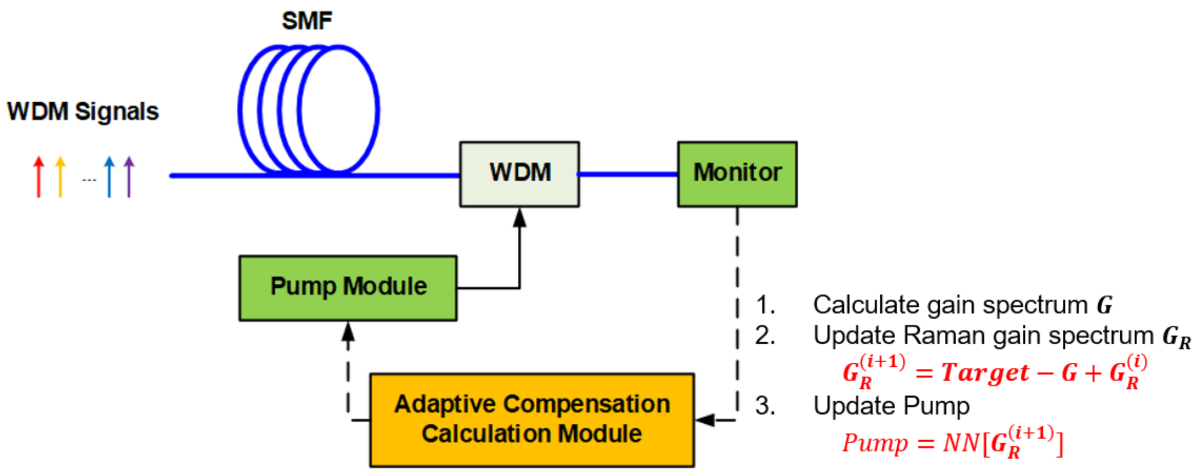
Above all, this method has great application potential in arbitrary and dynamic amplification. We can realize arbitrary gain spectrum to compensate the distortion of output signal spectrum induced by other device in communication systems. Considering the distortion of some device is time-variant, we can take advantage of waveshaper’s programmability to compensate the distortion in real-time, as
Figure 10 shows. Optical spectrum analyzer (OSA) or other device is used to monitor the spectrum of output signal. The adaptive compensation module will calculate the pump according to current spectrum and target, and then control the pump module to update the gain of DRA. This configuration can adaptively control the spectrum of output signal, avoiding dynamic change induced by other devices. For instance, we can regard this system as an integral module. When the signal fluctuates or changes occur during signal transmission, we can use this system to compensate it. When it happens, the compensation waveform is obtained through calculation, and then the system works to keep the signal stable or make the signal reach the target waveform.


