Article

Stretchable and Transparent Metal Nanowire Microelectrodes for Simultaneous Electrophysiology and Optogenetics Applications

Department of Biomedical Engineering, The George Washington University, Washington, DC 20052, USA
*
Author to whom correspondence should be addressed.
Photonics 2021, 8(6), 220; https://doi.org/10.3390/photonics8060220
Submission received: 23 May 2021 / Revised: 10 June 2021 / Accepted: 10 June 2021 / Published: 15 June 2021
(This article belongs to the Special Issue Bio-Integrated Photonic Materials and Devices)

Abstract

:
Recently developed optically transparent microelectrode technology provides a promising approach for simultaneous high-resolution electrical and optical biointerfacing with tissues in vivo and in vitro. A critically unmet need is designing high-performance stretchable platforms for conformal biointerfacing with mechanically active organs. Here, we report silver nanowire (Ag NW) stretchable transparent microelectrodes and interconnects that exhibit excellent electrical and electrochemical performance, high optical transparency, superior mechanical robustness and durability by a simple selective-patterning process. The fabrication method allows the direct integration of Ag NW networks on elastomeric substrates. The resulting Ag NW interface exhibits a low sheet resistance (Rsh) of 1.52–4.35 Ω sq−1, an advantageous normalized electrochemical impedance of 3.78–6.04 Ω cm2, a high optical transparency of 61.3–80.5% at 550 nm and a stretchability of 40%. The microelectrode arrays (MEAs) fabricated with this approach exhibit uniform electrochemical performance across all channels. Studies on mice demonstrate that both pristine and stretched Ag NW microelectrodes can achieve high-fidelity electrophysiological monitoring of cardiac activity with/without co-localized optogenetic pacing. Together, these results pave the way for developing stretchable and transparent metal nanowire networks for high-resolution opto-electric biointerfacing with mechanically active organs, such as the heart.

1. Introduction

Technologies that can interact with biological systems to record and modulate cell activity are crucial to biomedical research and medicine [1,2,3]. Electrophysiological recording is one such technique, which allows monitoring the physiological dynamics of various cells/tissues/organs with a high temporal and spatial resolution [4,5]. Optogenetics is another, which can modulate the activity of specific cell-types by using light-sensitive proteins; and it is functionally orthogonal to electrophysiological recording [6,7]. Bioelectronic devices that allow simultaneous electrophysiological recording with optogenetic modulation represent an emerging area to combine the advantages of both techniques for investigating the complex (patho)physiology of bioelectric organ systems [8]. Conventional microelectrodes used in electrophysiology studies primarily rely on opaque metals [9,10]. These microelectrodes are not ideal for multimodal device applications because they not only produce significant light-induced electrical artifacts during electrophysiological recording but also create optical shadows that block the field of view at the microelectrode sites, thereby preventing co-localized opto-electric operations [11,12,13].
Recent progress in transparent microelectrodes based on carbon nanotube (CNT) [14], graphene [15,16], metal nanogrid [17], metal nanonetwork [18], metal nanomesh [19], and poly(3,4-ethylenedioxythiophene)/poly(styrenesulfonate) (PEDOT:PSS)-indium tin oxide (ITO)-Ag-ITO [20] have enabled light delivery through the microelectrodes for electrophysiological recording with co-localized optogenetic stimulation or optical mapping. Although those transparent microelectrodes all exhibit certain levels of bendability/flexibility, only CNT demonstrates a high stretchability that is compliant enough to mount on curvilinear surfaces or interface with dynamically deforming organs, such as the heart muscle (~10% deformation) [21], the brain (up to 5% strain) [22], and the spinal cord (10–20% tensile strain) [22]. A stretchable microelectrode is desired because it will deform with the tissue while retaining the electrophysiological recording capabilities, which will allow real-time recording from the same anatomical site under natural motion. However, CNT recently raised concerns regarding its cytotoxicity as biointerfaces [23] and relative high impedance [14], which is undesirable in low noise electrophysiology studies. In addition, the quality of CNT is sensitive to fabrication methods [24,25].
One-dimensional metallic silver nanowire (Ag NW) is a widely used candidate material for stretchable transparent conductive electrodes in conventional optoelectronic devices, such as light-emitting diodes (LEDs) [26], displays [27,28], thin film transistors [29], and touch panels [30], owing to its outstanding electrical, optical, and mechanical properties. The nanowire network exhibits a high transparency because the open areas between the interconnected nanowires allow light to pass through. The stretchability results from the intersliding behavior of the nanowires. Our recent results show that the Ag NW structures are biocompatible and exhibit a much higher surface roughness than planar metal microelectrodes, which is beneficial to increase the effective surface area for electrophysiological recording applications [31]. However, until now, there has been few studies investigating Ag NW stretchable and transparent microelectrodes for multimodal biointerfacing.
In this work, we report high-performance stretchable and transparent microelectrodes and interconnects for simultaneous electrical and optical biointerfacing with mechanically active beating hearts based on Ag NW structures. The Ag NW networks are directly coated on stretchable and transparent elastomeric substrates using a selective-patterning process. The resulting Ag NW features show a high optical transparency up to 80.5% at 550 nm, a desired stretchability of 40% for biointerfacing, an excellent electrical conductivity with the sheet resistance (Rsh) of 1.52–4.35 Ω sq−1, and a low normalized electrochemical impedance of 3.78–6.04 Ω cm2. The effectiveness of the Ag NW microelectrodes and interconnects in multimodal biointerfacing under mechanically active environments is verified by simultaneous optogenetic stimulation and electrophysiological recording of ex vivo Langendorff-perfused mouse hearts. These results highlight the potential application of soft and transparent Ag NW microelectrodes in studies of complex, dynamically deforming, and mechanically active biological organ systems.

2. Materials and Methods

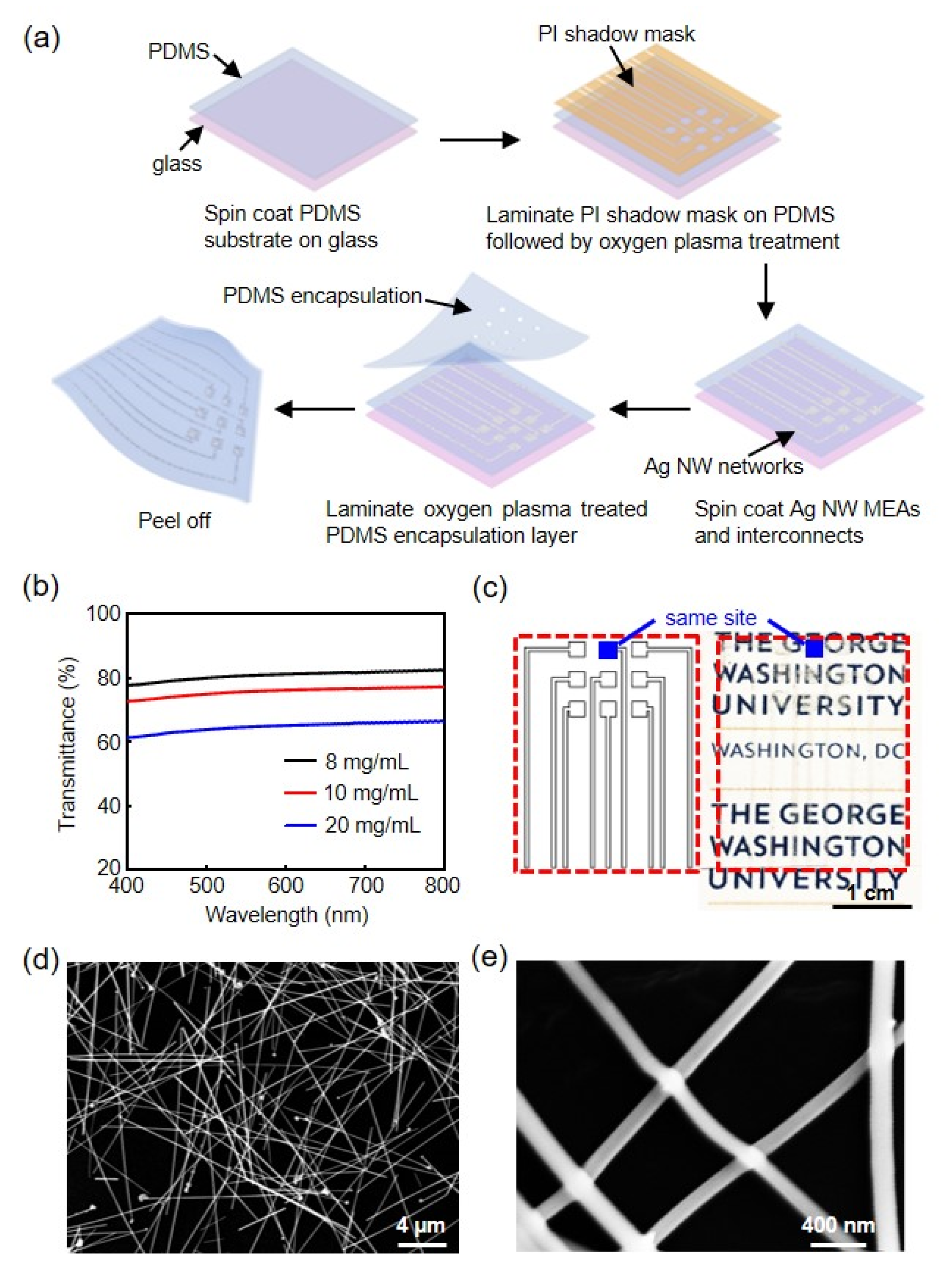
2.1. Fabrication of Stretchable Ag NW Microelectrodes and Interconnects

Figure 1a presents the schematic illustration of the fabrication process of the microelectrode array (MEA) and interconnects. Polydimethylsiloxane (PDMS) is used as the encapsulation and substrate material because it is biocompatible, optically transparent, chemically inert, thermally stable, and exhibits a high stretchability [32,33,34]. Firstly, PDMS substrate (~60 μm) was prepared by mixing the base and the curing agent (Sylgard 184, Dow Corning, Midland, MI, USA) at a ratio of 10:1 by weight. After vacuum degassing, the liquid mixture was spin-coated at 1000 rpm for 30 s onto a glass substrate, and thermally cured at 70 °C for 3 h to form a crosslinked PDMS. A laser mill defined ultrathin polyimide (PI) shadow mask film (DuPont, Wilmington, DE, USA) with desired patterns for the MEA, interconnects, and bonding pads was laminated onto the cured PDMS substrate, followed by oxygen plasma treatment (AutoGlow 100, Glow Research, Tempe, AZ, USA) at 20 W for 90 s. Next, the Ag NW/isopropyl alcohol solutions (ACS Material, Pasadena, CA, USA) were sonicated and spin-coated on plasma-treated PDMS at 500 rpm for 50 s. Plasma treatment is known to promote the adhesion between Ag NW and PDMS substrate [35]. Here, Ag NW networks were formed only on the plasma-treated PDMS region since the rest of the areas were still covered by the shadow mask. The resulting films were dried at 95 °C for 120 s. The PI shadow mask was then peeled off from the PDMS substrate. The PDMS encapsulation layer (~60 μm) was prepared in the same manner as the PDMS substrate, with an additional spin-coated polymethyl methacrylate (Microchem, Round Rock, TX, USA) sacrificial layer on the glass slide. The microelectrode opening areas on the PDMS encapsulation layer were defined by laser milling. The PDMS encapsulation layer was released in acetone, treated with oxygen plasma, and quickly laminated on the Ag NW/PDMS substrate. The completed device was peeled off from the glass slide.

2.2. Measurements

Optical properties of the Ag NW films were obtained using a spectrophotometer (V-770 UV-vis/NIR, Jasco Inc., Easton, MD, USA). Scanning electron microscope (SEM) images were taken with a Raith Pioneer instrument. Mechanical tests were performed using a motorized test stand (ESM 1500, Mark-10, Copiague, NY, USA). Sheet resistance values of the Ag NW structures were obtained from a four-point probe (SRM-232, Guardian Manufacturing Inc., Cocoa, FL, USA). Electrochemical impedance was measured with a Gamry potentiostat (Reference 600+, Gamry Instruments Inc., Warminster, PA, USA) with a frequency that ranges from 1 Hz to 10 kHz. The electrochemical measurements were performed in a 1× phosphate-buffered saline (PBS) solution (Sigma-Aldrich, St. Louis, MO, USA) using a three-electrode configuration with Ag NW microelectrodes as the working electrode, a platinum electrode as the counter electrode, and an Ag/AgCl electrode as the reference electrode. The benchtop recording tests were conducted with a PowerLab data acquisition system (PowerLab 16/35, AD Instruments Inc., Colorado Springs, CO, USA). A 10 Hz sine wave signal with a 20 mV peak-to-peak amplitude was delivered through a platinum electrode in a 1× PBS solution. The Ag NW microelectrodes and another platinum electrode were connected to different channels of the PowerLab system for comparing the recorded signals. MATLAB (MathWorks, Inc., Natick, MA, USA) was used to process and analyze the signals.

2.3. Animal Experiments

All animal procedures were performed according to protocols approved by the Institutional Animal Care and Use Committee of the George Washington University and in conformance with Guide for the Care and Use of Laboratory Animals published by the National Institutes of Health. Adult mice (The Jackson Laboratory, Bar Harbor, ME, USA) with cardiomyocytes expressing channelrhodopsin-2 (ChR2) were used for the ex vivo demonstration. Mice were anesthetized with 5% isoflurane in an anesthesia chamber. Cervical dislocation was immediately performed after the mice were fully anesthetized and unresponsive to physical stimuli. The chests were opened, and the hearts were quickly excised following thoracotomy. After aortic cannulation, the hearts were perfused in constant pressure (70–90 mmHg) mode in a Langendorff system with a modified Tyrode’s solution (in mM: NaCl 140, KCl 4.7, MgCl2 1.05, CaCl2 1.3, HEPES 10, Glucose 11.1, pH 7.4 at 37 °C) bubbled with 100% O2. 10–12 μM of blebbistatin (Cayman Chemical, Ann Arbor, MI, USA) was applied as an excitation-contraction uncoupler. The Ag NW microelectrodes were placed at the anterior side of the heart inside the left ventricular region. For optogenetic pacing, a blue (462 nm) LED (OptoLED Lite, Cairn Research, Faversham, UK) was used as the light source. An optical fiber was connected to the LED and placed above the Ag NW microelectrodes. Optical stimulation was set at 7.8 Hz and 9 Hz at 15% duty cycle to induce pacing rates above the intrinsic heart rhythm. Electrical recordings were performed in the three-electrode configuration using the Ag NW microelectrodes or a far-field needle electrode (MLA1203, AD Instruments Inc.) as the working electrode. The capture of pacing was verified in both reference electrocardiogram (ECG) from the needle electrode and electrogram (EG) from the Ag NW microelectrodes. Signals were acquired at the sampling frequency of 2 kHz and analyzed using the LabChart software (AD Instruments Inc.).

3. Results

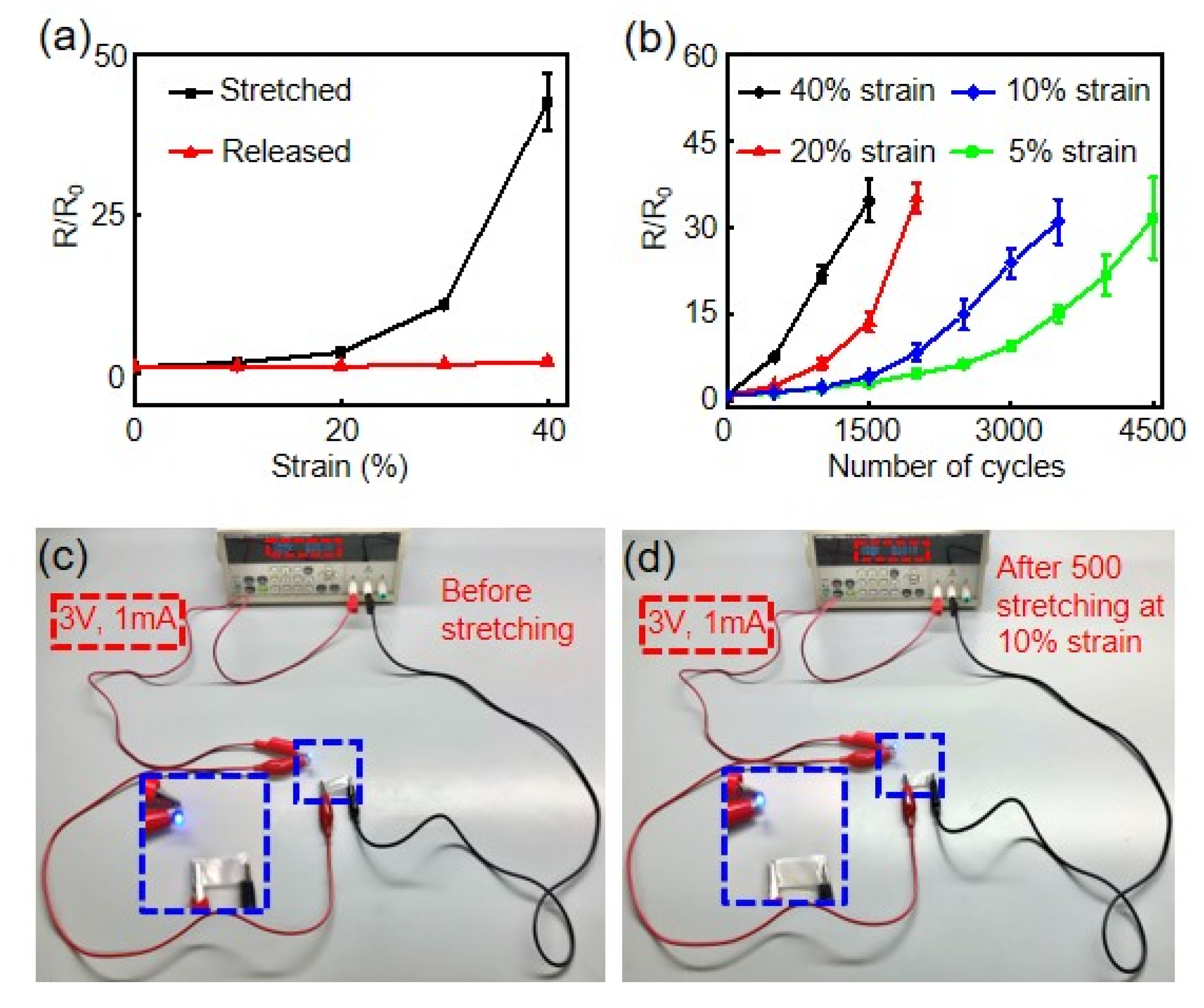
3.1. Optical, Electrical, and Mechanical Properties of Ag NW Structures

The Ag NW network density is controlled by the concentrations of Ag NW/isopropyl alcohol solutions used in fabrication. Figure 1b presents the transmittance spectra of Ag NW networks. The average transmittance values at 550 nm over 5 devices increase from 61.3 ± 2.16% to 75.2 ± 1.75%, and 80.5 ± 1.24% with the Ag NW concentrations decreasing from 20 mg/mL to 10 mg/mL, and finally 8 mg/mL, respectively. Figure 1c shows an optical image of an as fabricated 3 × 3 Ag NW MEA and interconnects on PDMS. The pitch between different microelectrode sites is 2.15 mm and the dimension of a single microelectrode is 650 × 650 μm2. The same microelectrode dimension is used in the rest of this paper. The entire device shows a high optical transparency, including the MEA recording sites and interconnect lines. Figure 1d presents a representative SEM image of the Ag NW (10 mg/mL) networks on PDMS. The nanowires have a diameter ~120 nm (Figure 1e) and a length between 10 and 20 μm.
The average Rsh values increase from 1.52 ± 0.3 Ω sq−1 to 3.77 ± 0.3 Ω sq−1, and 4.35 ± 0.2 Ω sq−1 with the nanowire concentrations decreasing from 20 mg/mL to 10 mg/mL, and 8 mg/mL due to the reduced Ag NW density in the conductive networks. The electrical performance of our Ag NW structures is comparable to other stretchable and transparent Ag NW electrodes used in traditional optoelectronic applications [30,35,36], and outperforms the CNT interconnects at similar transmittance values [14].
To demonstrate the mechanical robustness of the Ag NW/PDMS structures against cyclic strain experienced by many mechanically active tissues, strain tests of the Ag NW/PDMS films are performed with 2.5 × 3.5 cm2 in size. Figure 2a shows the one-time stretching performance. The Ag NW/PDMS films exhibit unchanged resistance at the released state for up to 40% strain. Figure 2b shows the reliability over continuous cyclic deformation. The resistance remains stable for over 500 cycles of stretching for up to 20% strain. At 40% strain, the released Ag NW films show a dramatically increased resistance after 500 cycles of stretching. This is due to the delamination of the Ag NW junctions under continuous large mechanical stress [30]. Figure S1 shows the SEM image of the Ag NW networks after 4500 cycles of stretching at 40% strain. A clear decrease in the Ag NW network density is observed compared to the pristine film in Figure 1d. Figure 2c,d show optical images of a blue LED device connected to a voltage source using the Ag NW/PDMS films before and after continuous cyclic strain of 10% for 500 cycles. The current and voltage readings shown on the voltage source indicate the resistance of the system remains unchanged after stretching, confirming the stable electrical performance of the Ag NW networks after 500 cycles of stretching at 10% strain.

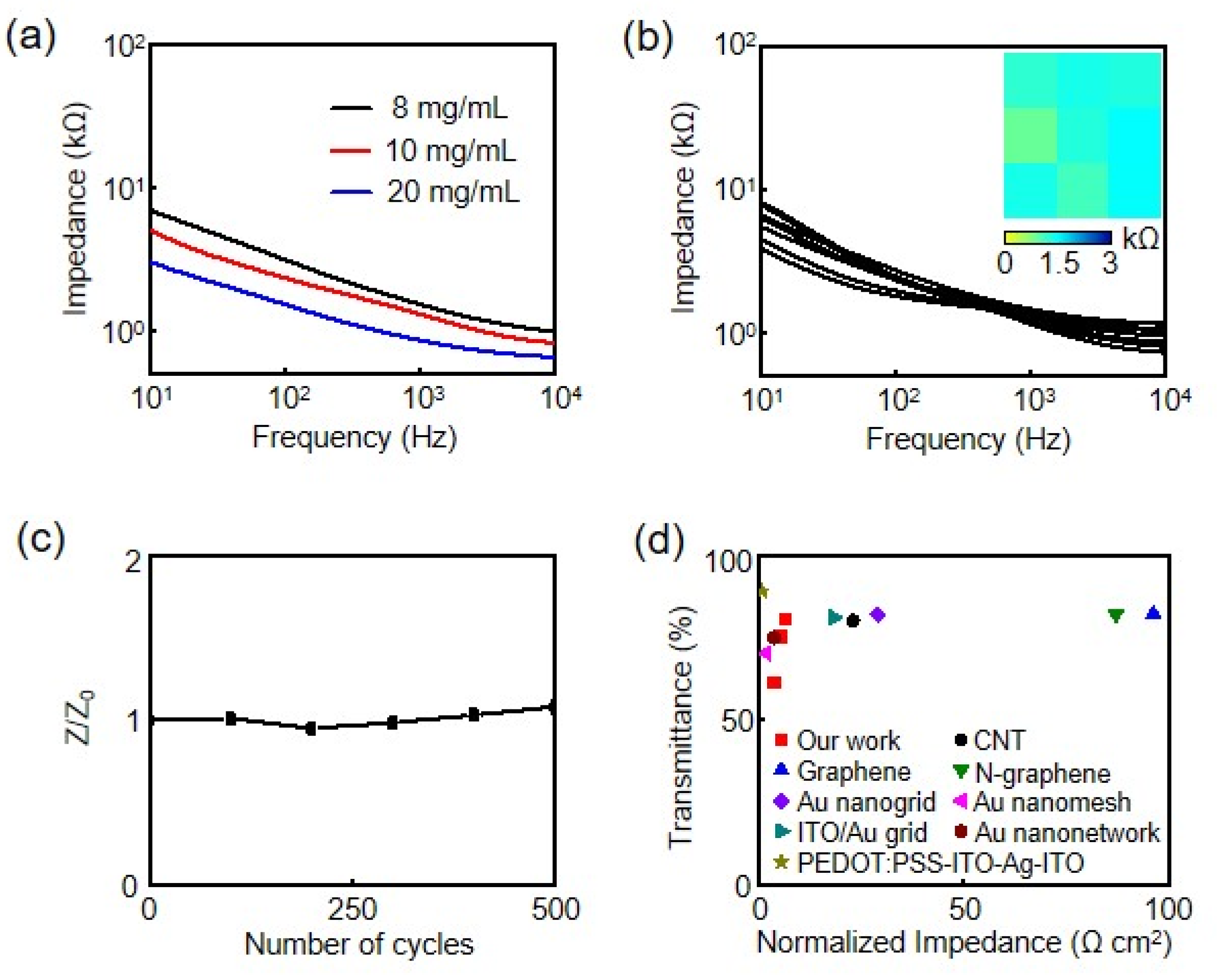
3.2. Electrochemical Properties of Ag NW Microelectrodes

Electrochemical impedance represents the performance of a microelectrode at the abiotic/biotic interface and is an important characteristic of a microelectrode for electrophysiological recording. A low impedance magnitude is desired to improve the recording quality and achieve a high signal-to-noise ratio (SNR). Figure 3a presents the impedance of Ag NW microelectrodes with different Ag NW concentrations measured by electrochemical impedance spectroscopy in a PBS solution. The frequency range of 10 Hz to 10 kHz covers different frequency bands to include both low-frequency and high-frequency biosignals. Impedance values at 1 kHz are widely used for comparison of different electrophysiological recording microelectrodes [13]. The average impedance values over 5 devices at 1 kHz for the Ag NW microelectrodes decrease from 1.43 ± 0.07, to 1.30 ± 0.07, and 0.896 ± 0.08 kΩ with Ag NW concentrations increasing from 8 mg/mL to 10 mg/mL, and 20 mg/mL, respectively. Similar to the changes in Rsh, the smaller impedance values at larger Ag NW concentrations are due to the increased nanowire network density that improves the effective interfacial areas of the microelectrodes. The uniformity of the nanowire networks is important to achieve robust electrochemical performance over a large area [37,38,39]. Figure 3b shows the impedance responses of 9 Ag NW microelectrodes in the 3 × 3 MEA in Figure 1c. It is clear that the MEA exhibits a uniform electrochemical performance across all channels with an average impedance of 1.30 ± 0.1 kΩ, which is crucial for simultaneous high-fidelity electrophysiological recording at multiple sites and studying the propagation of biosignals. The impedance results of the Ag NW microelectrodes are fitted with an equivalent circuit model in Figure S2, which consists of solution resistance (RS), charge transfer resistance (RCT), Warburg element for diffusion (ZWD), and constant phase element (ZCPE). ZCPE is defined by 1 Y 0 ( j ω ) n , where j is the unit imaginary number, ω is the angular frequency, Y0 is the magnitude of ZCPE, and n is a constant defined by the phase angle of ZCPE. The n value of our Ag NW microelectrodes is 0.73, which suggests a more capacitive interface [17]. Importantly, the impedance of the Ag NW microelectrodes remains nearly unchanged as they are stretched over continuous cyclic strain of 10% for 500 cycles (Figure 3c).
The performance of our Ag NW microelectrodes are compared to previously reported flexible transparent microelectrodes for electrophysiology studies (Figure 3d), including CNT [14], graphene [16], nitrogen-doped graphene (N-graphene) [40], Au nanogrid [17], Au bilayer nanomesh [41], ITO/Au grid [42], Au nanonetwork [18], and PEDOT:PSS-ITO-Ag-ITO [20]. For fair comparison, transmittance values at 550 nm are used while all impedance values are at 1 kHz and have been normalized to the actual dimension of each microelectrode. Our stretchable Ag NW microelectrodes exhibit low normalized impedance values (3.78, 5.49, and 6.04 Ω cm2) at moderate to high optical transmittance levels (61.3%, 75.2%, and 80.5%). This is among the best performance for transparent microelectrodes and also comparable to those from opaque solid Ag film microelectrodes we previously reported [31].
We further demonstrate the recording capability and mechanical robustness of the Ag NW microelectrodes using benchtop tests. Figure 4a demonstrates the benchtop recording results of an acute sine wave input signal (10 Hz and 20 mV peak-to-peak amplitude) in a 1× PBS solution from the Ag NW microelectrodes. The power spectrum density (PSD) of the signals in Figure 4b provides detailed noise and signal information in the frequency domain. The large peak at 10 Hz originates from the input signal. The calculated SNR is 40.7 dB. Figure 4c shows that the Ag NW microelectrodes can record the same sine wave input signal with high-fidelity and no decrease in amplitude after been stretched at 10% strain for 500 cycles. The SNR from the PSD results in Figure 4d is 39.8 dB, respectively, which is almost identical to the SNR for the pristine microelectrodes in Figure 4b. The average SNRs from 5 devices before and after 500 cycles of stretching at 10% strain are 41.1 ± 0.7 dB and 39.8 ± 1.7 dB, respectively. Importantly, the SNRs remain stable even after further stretching to 1000 cycles (38.9 ± 2.0 dB).

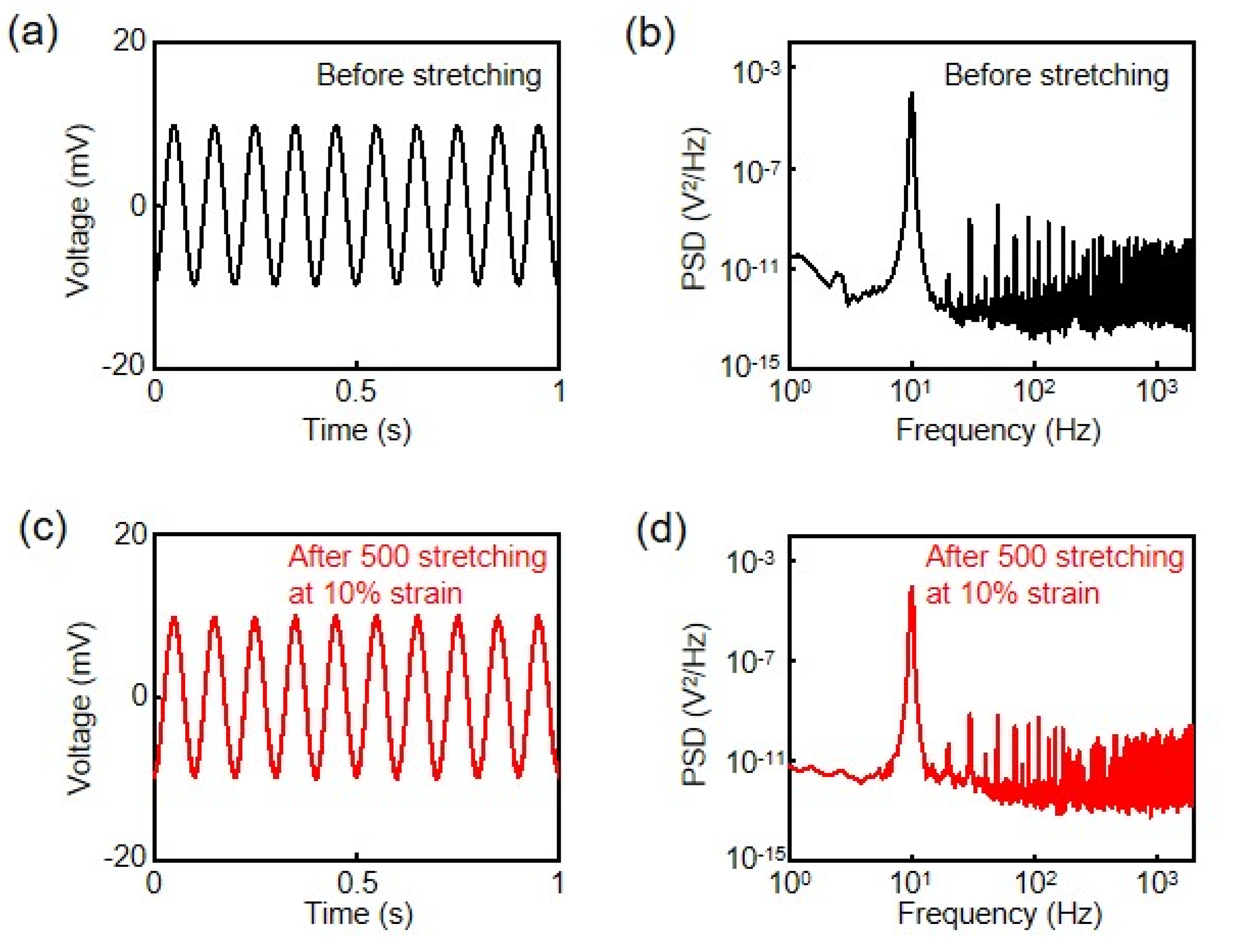
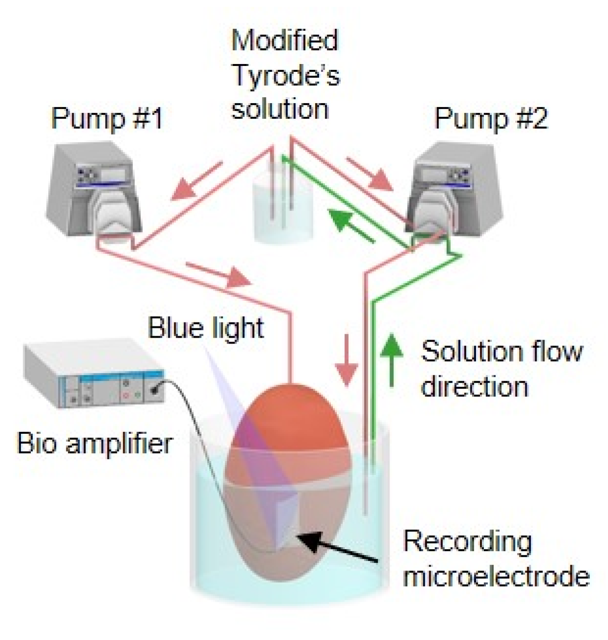
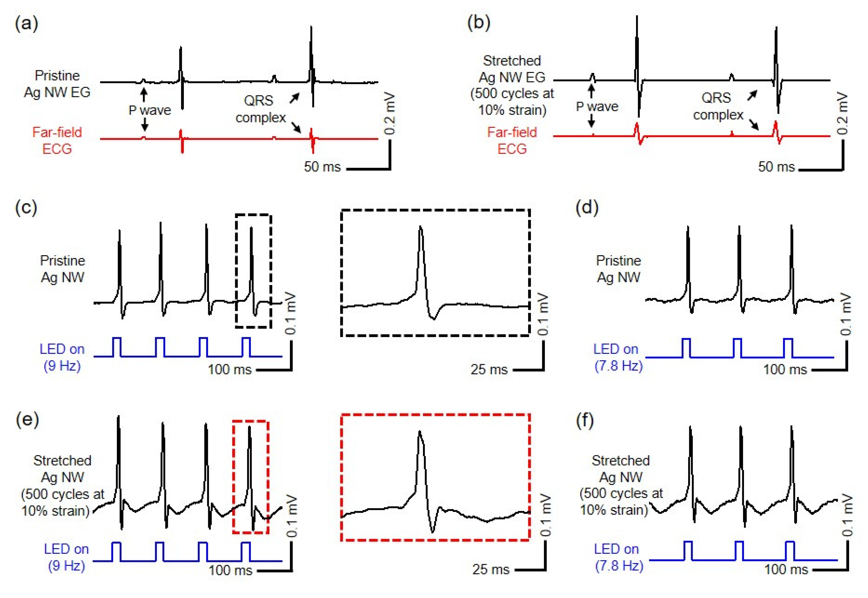
3.3. Ex Vivo Cardiac Electrophysiological Recording and Optogenetic Pacing

The stretchable and transparent Ag NW microelectrodes and interconnects allow for simultaneous and co-localized optogenetic modulation and electrophysiological recording, where photons pass through the device and illuminate the cell/tissue regions from which the electrophysiological recordings are obtained. Figure 5 shows the experimental setup. Concurrent optogenetic stimulation and cardiac recording from transgenic mouse hearts expressing ChR2 are performed using the Ag NW microelectrodes. Figure 6a shows the sinus rhythm recording results using a commercial reference electrode and pristine Ag NW microelectrodes. The EG results from the Ag NW microelectrodes and ECG signals from the reference electrode show similar morphology. The average durations of five QRS complexes from the reference electrode and Ag NW microelectrodes are 10.4 ± 0.5 ms and 10.2 ± 0.5 ms, respectively. Those results indicate the high-fidelity recording capabilities of the Ag NW microelectrodes. Figure 6b presents the recording results from a different mouse heart using the reference electrode and stretched Ag NW microelectrodes (10% strain, 500 cycles). Similarly, the morphology of the signals shows strong correlations. The average durations of the QRS complexes are 10.4 ± 0.6 ms and 10.2 ± 0.8 ms for the stretched Ag NW microelectrodes and reference electrode, respectively. Those results suggest that both the pristine and stretched Ag NW microelectrodes can quantitatively record cardiac activity with high precision.
Optogenetic pacing of ChR2-expressing cardiomyocytes underneath the Ag NW microelectrodes is then performed. Figure 6c presents the recorded EG signals from the Ag NW microelectrodes during optogenetic pacing at 9 Hz with a duty cycle at 15% (blue traces). The average RR interval is 111.0 ± 0.3 ms, which is consistent with our previous findings that the cardiac activity could be precisely controlled by optogenetic stimulation [17]. The EG recording results from the Ag NW microelectrodes in Figure 6d confirm the successful pacing of the heart rhythm under a different optogenetic pacing frequency at 7.8 Hz. Moreover, results in Figure 6e, f suggest that the stretched (10% strain, 500 cycles) Ag NW microelectrodes can also record the cardiac activity under different pacing frequencies with high-fidelity. For example, the average RR interval value recorded by the stretched Ag NW microelectrodes during 9 Hz optogenetic pacing is 111.0 ± 0.2 ms, which is almost identical to the results in Figure 6c. Overall, the Ag NW microelectrodes enable reliable co-localized monitoring of continuously beating hearts with/without optogenetic modulation and are valuable to study normal and pathological cardiac physiology.

4. Conclusions

In summary, Ag NW stretchable and transparent MEAs and interconnects with excellent mechanical, optical, electrical, and electrochemical properties have been achieved by sandwiching patterned Ag NW structures between PDMS substrate and encapsulation layers. This simple and easy approach also allows fabrication of nanowire based MEAs with a high uniformity. We expect this fabrication approach to be applicable to many different metal nanowire systems. Proof-of-concept demonstrations indicate that both pristine and stretched Ag NW microelectrodes allow real-time high-fidelity electrophysiological recording of heart rhythm under simultaneous optogenetic pacing. The approach presented here shows the significant potential of metal nanowire microelectrode technology in combining electrophysiology with optophysiology to investigate dynamically deforming organ systems.

Supplementary Materials

The following are available online at https://www.mdpi.com/article/10.3390/photonics8060220/s1, Figure S1: SEM image of the Ag NW structures at 10 mg/mL after 4500 stretching cycles at 40% strain. Figure S2: Equivalent circuit model with fitting parameters Rs, RCT, ZWD, and ZCPE.

Author Contributions

L.L. conceived the basic design of this study and the experiments; J.T., Z.L., Z.C. and S.N.O. performed the experiments; L.L., J.T., Z.L. and I.R.E. analyzed the data and wrote this paper; L.L. and I.R.E. supervised the experiments. All authors contributed to the general discussion of the manuscript. All authors have read and agreed to the published version of the manuscript.

Funding

This research was funded by the National Science Foundation (ECCS 2011093), National Institutes of Health (R21HL152324, 3OT2OD023848 and R01HL141470), Leducq Foundation grant RHYTHM, the George Washington University Cross-Disciplinary Research Fund, University Facilitating Fund from the George Washington University, and the George Washington University COVID-19 Research Fund.

Institutional Review Board Statement

Not Applicable.

Informed Consent Statement

Not Applicable.

Data Availability Statement

The data are available from the corresponding author upon reasonable request.

Acknowledgments

We thank the George Washington University Nanofabrication and Imaging Center and the George Washington University School of Engineering and Applied Science machine shop for their facilities regarding device fabrications.

Conflicts of Interest

The authors declare no conflict of interest.

References

  1. Vázquez-Guardado, A.; Yang, Y.; Bandodkar, A.J.; Rogers, J.A. Recent advances in neurotechnologies with broad potential for neuroscience research. Nat. Neurosci. 2020, 23, 1522–1536. [Google Scholar] [CrossRef]
  2. Cai, L.; Gutruf, P. Soft, wireless and subdermally implantable recording and neuromodulation tools. J. Neural Eng. 2021, 18, 041001. [Google Scholar] [CrossRef] [PubMed]
  3. Ershad, F.; Sim, K.; Thukral, A.; Zhang, Y.S.; Yu, C. Invited Article: Emerging soft bioelectronics for cardiac health diagnosis and treatment. APL Mater. 2019, 7, 031301. [Google Scholar] [CrossRef] [PubMed] [Green Version]
  4. Hong, G.; Lieber, C.M. Novel electrode technologies for neural recordings. Nat. Rev. Neurosci. 2019, 20, 330–345. [Google Scholar] [CrossRef]
  5. Han, M.; Chen, L.; Aras, K.; Liang, C.; Chen, X.; Zhao, H.; Li, K.; Faye, N.R.; Sun, B.; Kim, J.-H.; et al. Catheter-integrated soft multilayer electronic arrays for multiplexed sensing and actuation during cardiac surgery. Nat. Biomed. Eng. 2020, 4, 997–1009. [Google Scholar] [CrossRef]
  6. Kim, C.; Adhikari, A.; Deisseroth, A.A.K. Integration of optogenetics with complementary methodologies in systems neuroscience. Nat. Rev. Neurosci. 2017, 18, 222–235. [Google Scholar] [CrossRef]
  7. Fenno, L.; Yizhar, O.; Deisseroth, K. The Development and Application of Optogenetics. Annu. Rev. Neurosci. 2011, 34, 389–412. [Google Scholar] [CrossRef]
  8. Ramezani, Z.; Seo, K.J.; Fang, H. Hybrid electrical and optical neural interfaces. J. Micromech. Microeng. 2021, 31, 044002. [Google Scholar] [CrossRef]
  9. Obien, M.E.J.; Edeligkaris, K.; Ebullmann, T.; Bakkum, D.J.; Frey, U. Revealing neuronal function through microelectrode array recordings. Front. Neurosci. 2015, 8, 423. [Google Scholar] [CrossRef] [PubMed] [Green Version]
  10. Jun, J.J.; Steinmetz, N.A.; Siegle, J.H.; Denman, D.J.; Bauza, M.; Barbarits, B.; Lee, A.K.; Anastassiou, C.A.; Andrei, A.; Aydin, C.; et al. Fully integrated silicon probes for high-density recording of neural activity. Nat. Cell Biol. 2017, 551, 232–236. [Google Scholar] [CrossRef] [PubMed] [Green Version]
  11. Wu, F.; Stark, E.; Ku, P.-C.; Wise, K.D.; Buzsáki, G.; Yoon, E. Monolithically Integrated μLEDs on Silicon Neural Probes for High-Resolution Optogenetic Studies in Behaving Animals. Neuron 2015, 88, 1136–1148. [Google Scholar] [CrossRef] [Green Version]
  12. Park, D.-W.; Ness, J.P.; Brodnick, S.K.; Esquibel, C.; Novello, J.; Atry, F.; Baek, D.-H.; Kim, H.; Bong, J.; Swanson, K.I.; et al. Electrical Neural Stimulation and Simultaneous in Vivo Monitoring with Transparent Graphene Electrode Arrays Implanted in GCaMP6f Mice. ACS Nano 2018, 12, 148–157. [Google Scholar] [CrossRef] [PubMed]
  13. Obaid, S.N.; Chen, Z.; Lu, L. Advanced Electrical and Optical Microsystems for Biointerfacing. Adv. Intell. Syst. 2020, 2, 2000091. [Google Scholar] [CrossRef]
  14. Zhang, J.; Liu, X.; Xu, W.; Luo, W.; Li, M.; Chu, F.; Xu, L.; Cao, A.; Guan, J.-S.; Tang, S.; et al. Stretchable Transparent Electrode Arrays for Simultaneous Electrical and Optical Interrogation of Neural Circuits in Vivo. Nano Lett. 2018, 18, 2903–2911. [Google Scholar] [CrossRef] [PubMed]
  15. Park, D.-W.; Schendel, A.A.; Mikael, S.; Brodnick, S.K.; Richner, T.; Ness, J.P.; Hayat, M.R.; Atry, F.; Frye, S.T.; Pashaie, R.; et al. Graphene-based carbon-layered electrode array technology for neural imaging and optogenetic applications. Nat. Commun. 2014, 5, 5258. [Google Scholar] [CrossRef] [PubMed]
  16. Thunemann, M.; Lu, Y.; Liu, X.; Kılıç, K.; Desjardins, M.; Vandenberghe, M.; Sadegh, S.; Saisan, P.A.; Cheng, Q.; Weldy, K.L.; et al. Deep 2-photon imaging and artifact-free optogenetics through transparent graphene microelectrode arrays. Nat. Commun. 2018, 9, 2035. [Google Scholar] [CrossRef] [PubMed]
  17. Obaid, S.N.; Yin, R.T.; Tian, J.; Chen, Z.; Chen, S.W.; Lee, K.B.; Boyajian, N.; Miniovich, A.N.; Efimov, I.R.; Lu, L. Multifunctional Flexible Biointerfaces for Simultaneous Colocalized Optophysiology and Electrophysiology. Adv. Funct. Mater. 2020, 30, 1910027. [Google Scholar] [CrossRef]
  18. Seo, J.; Kim, K.; Kim, M.K.; Jeong, S.; Kim, H.; Ghim, J.; Lee, J.H.; Choi, N.; Lee, J.; Lee, H.J. Artifact-Free 2D Mapping of Neural Activity In Vivo through Transparent Gold Nanonetwork Array. Adv. Funct. Mater. 2020, 30, 2000896. [Google Scholar] [CrossRef]
  19. Qiang, Y.; Artoni, P.; Seo, K.J.; Culaclii, S.; Hogan, V.; Zhao, X.; Zhong, Y.; Han, X.; Wang, P.-M.; Lo, Y.-K.; et al. Transparent arrays of bilayer-nanomesh microelectrodes for simultaneous electrophysiology and two-photon imaging in the brain. Sci. Adv. 2018, 4, eaat0626. [Google Scholar] [CrossRef] [Green Version]
  20. Yang, W.; Gong, Y.; Yao, C.-Y.; Shrestha, M.; Jia, Y.; Qiu, Z.; Fan, Q.H.; Weber, A.; Li, W. A fully transparent, flexible PEDOT:PSS–ITO–Ag–ITO based microelectrode array for ECoG recording. Lab Chip. 2021, 21, 1096–1108. [Google Scholar] [CrossRef]
  21. Lee, S.P.; Klinker, L.E.; Ptaszek, L.; Work, J.; Liu, C.; Quivara, F.; Webb, C.; Dagdeviren, C.; Wright, J.A.; Ruskin, J.N.; et al. Catheter-Based Systems With Integrated Stretchable Sensors and Conductors in Cardiac Electrophysiology. Proc. IEEE 2015, 103, 682–689. [Google Scholar] [CrossRef]
  22. Bayly, P.; Cohen, T.; Leister, E.; Ajo, D.; Leuthardt, E.; Genin, G. Deformation of the Human Brain Induced by Mild Acceleration. J. Neurotrauma 2005, 22, 845–856. [Google Scholar] [CrossRef] [PubMed] [Green Version]
  23. Hansen, S.F.; Lennquist, A. Carbon nanotubes added to the SIN List as a nanomaterial of Very High Concern. Nat. Nanotechnol. 2020, 15, 3–4. [Google Scholar] [CrossRef]
  24. Hwang, M.-Y.; Kang, L.-H. Analysis of Important Fabrication Factors That Determine the Sensitivity of MWCNT/Epoxy Composite Strain Sensors. Materials 2019, 12, 3875. [Google Scholar] [CrossRef] [PubMed] [Green Version]
  25. Anzar, N.; Hasan, R.; Tyagi, M.; Yadav, N.; Narang, J. Carbon nanotube—A review on Synthesis, Properties and plethora of applications in the field of biomedical science. Sens. Int. 2020, 1, 100003. [Google Scholar] [CrossRef]
  26. Liang, J.; Li, L.; Tong, K.; Ren, Z.; Hu, W.; Niu, X.; Chen, Y.; Pei, Q. Silver Nanowire Percolation Network Soldered with Graphene Oxide at Room Temperature and Its Application for Fully Stretchable Polymer Light-Emitting Diodes. ACS Nano 2014, 8, 1590–1600. [Google Scholar] [CrossRef]
  27. Yan, C.; Kang, W.; Wang, J.; Cui, M.; Wang, X.; Foo, C.Y.; Chee, K.J.; Lee, P.S. Stretchable and Wearable Electrochromic Devices. ACS Nano 2014, 8, 316–322. [Google Scholar] [CrossRef] [PubMed]
  28. Lin, Y.; Yuan, W.; Ding, C.; Chen, S.; Su, W.; Hu, H.; Cui, Z.; Li, F. Facile and Efficient Patterning Method for Silver Nanowires and Its Application to Stretchable Electroluminescent Displays. ACS Appl. Mater. Interfaces 2020, 12, 24074–24085. [Google Scholar] [CrossRef]
  29. Liang, J.; Li, L.; Chen, D.; Hajagos, T.; Ren, Z.; Chou, S.-Y.; Hu, W.; Pei, Q. Intrinsically stretchable and transparent thin-film transistors based on printable silver nanowires, carbon nanotubes and an elastomeric dielectric. Nat. Commun. 2015, 6, 7647. [Google Scholar] [CrossRef] [PubMed] [Green Version]
  30. Lee, H.; Lee, K.; Park, J.T.; Kim, W.C.; Lee, H. Well-Ordered and High Density Coordination-Type Bonding to Strengthen Contact of Silver Nanowires on Highly Stretchable Polydimethylsiloxane. Adv. Funct. Mater. 2014, 24, 3276–3283. [Google Scholar] [CrossRef]
  31. Chen, Z.; Boyajian, N.; Lin, Z.; Yin, R.T.; Obaid, S.N.; Tian, J.; Brennan, J.A.; Chen, S.W.; Miniovich, A.N.; Lin, L.; et al. Flexible and Transparent Metal Nanowire Microelectrode Arrays and Interconnects for Electrophysiology, Optogenetics, and Optical Mapping. Adv. Mater. Technol. 2021, 2100225. [Google Scholar] [CrossRef]
  32. Someya, T.; Bao, Z.; Malliaras, G.G. The rise of plastic bioelectronics. Nature 2016, 540, 379–385. [Google Scholar] [CrossRef]
  33. Schmid, H.; Michel, B. Siloxane Polymers for High-Resolution, High-Accuracy Soft Lithography. Macromolecules 2000, 33, 3042–3049. [Google Scholar] [CrossRef]
  34. McDonald, J.C.; Whitesides, G.M. Poly(dimethylsiloxane) as a Material for Fabricating Microfluidic Devices. Accounts Chem. Res. 2002, 35, 491–499. [Google Scholar] [CrossRef]
  35. You, B.; Kim, Y.; Ju, B.-K.; Kim, J.-W. Highly Stretchable and Waterproof Electroluminescence Device Based on Superstable Stretchable Transparent Electrode. ACS Appl. Mater. Interfaces 2017, 9, 5486–5494. [Google Scholar] [CrossRef]
  36. Liang, F.-C.; Chang, Y.-W.; Kuo, C.-C.; Cho, C.-J.; Jiang, D.-H.; Jhuang, F.-C.; Rwei, S.-P.; Borsali, R. A mechanically robust silver nanowire–polydimethylsiloxane electrode based on facile transfer printing techniques for wearable displays. Nanoscale 2019, 11, 1520–1530. [Google Scholar] [CrossRef] [PubMed]
  37. Schrenker, N.J.; Xie, Z.; Schweizer, P.; Moninger, M.; Werner, F.; Karpstein, N.; Mačković, M.; Spyropoulos, G.D.; Göbelt, M.; Christiansen, S.; et al. Microscopic Deformation Modes and Impact of Network Anisotropy on the Mechanical and Electrical Performance of Five-fold Twinned Silver Nanowire Electrodes. ACS Nano 2021, 15, 362–376. [Google Scholar] [CrossRef] [PubMed]
  38. Langley, D.P.; Lagrange, M.; Nguyen, N.D.; Bellet, D. Percolation in networks of 1-dimensional objects: Comparison between Monte Carlo simulations and experimental observations. Nanoscale Horiz. 2018, 3, 545–550. [Google Scholar] [CrossRef] [PubMed]
  39. Ackermann, T.; Neuhaus, R.; Roth, S. The effect of rod orientation on electrical anisotropy in silver nanowire networks for ultra-transparent electrodes. Sci. Rep. 2016, 6, 34289. [Google Scholar] [CrossRef] [PubMed] [Green Version]
  40. Kuzum, D.; Takano, H.; Shim, E.; Reed, J.; Juul, H.; Richardson, A.G.; De Vries, J.; Bink, H.; Dichter, M.A.; Lucas, T.H.; et al. Transparent and flexible low noise graphene electrodes for simultaneous electrophysiology and neuroimaging. Nat. Commun. 2014, 5, 5259. [Google Scholar] [CrossRef]
  41. Qiang, Y.; Seo, K.J.; Zhao, X.; Artoni, P.; Golshan, N.H.; Culaclii, S.; Wang, P.-M.; Liu, W.; Ziemer, K.S.; Fagiolini, M.; et al. Bilayer Nanomesh Structures for Transparent Recording and Stimulating Microelectrodes. Adv. Funct. Mater. 2017, 27, 1704117. [Google Scholar] [CrossRef]
  42. Chen, Z.; Yin, R.T.; Obaid, S.N.; Tian, J.; Chen, S.W.; Miniovich, A.N.; Boyajian, N.; Efimov, I.R.; Lu, L. Flexible and Transpar-ent Metal Oxide/Metal Grid Hybrid Interfaces for Electrophysiology and Optogenetics. Adv. Mater. Technol. 2020, 5, 2000322. [Google Scholar] [CrossRef]
Figure 1. (a) Schematic illustration of the fabrication steps for the stretchable and transparent Ag NW MEA and interconnects. (b) Transmittance spectra of Ag NW networks. (c) (Left) Schematic design of a 3 × 3 Ag NW MEA and interconnects. The inner blue box highlights a microelectrode in the MEA. (Right) Photograph of the 3 × 3 Ag NW MEA and interconnects to show the high optical transparency. The device areas are highlighted by the red dashed box. (d) SEM image of the Ag NW structures at 10 mg/mL. (e) Magnified SEM image of the Ag NW structures.
Photonics 08 00220 g001
Figure 2. (a) Relative changes of resistance under stretching strain. (b) Relative changes of resistance after cyclic stretching cycles to different strains. R0 is the resistance before stretching, whereas R represents the resistance at a specific stretching cycle. The results are averaged over 5 devices. Photos of an operating blue LED connected by Ag NW/PDMS films (c) before and (d) after 500 stretching cycles at 10% strain.
Photonics 08 00220 g002
Figure 3. (a) Impedance plot of the Ag NW microelectrodes. (b) Impedance spectra of all 9 microelectrodes in a 9-channel Ag NW MEA. (c) Variation of impedance versus stretching cycle for Ag NW microelectrodes at a strain of 10%. Z0 is the initial impedance, whereas Z represents the impedance at a specific stretching cycle. The results are averaged over 5 devices. (d) Normalized impedance of Ag NW microelectrodes versus transmittance compared to major reported flexible transparent microelectrodes such as CNT [14], graphene [16], nitrogen-doped graphene (N-graphene) [40], Au nanogrid [17], Au bilayer nanomesh [41], ITO/Au grid [42], Au nanonetwork [18], and PEDOT:PSS-ITO-Ag-ITO [20].
Photonics 08 00220 g003
Figure 4. (a) Benchtop recording results from the pristine Ag NW microelectrodes, with a 20 mV peak-to-peak amplitude, 10 Hz sine wave input. (b) PSD of the electrical signals recorded by the Ag NW microelectrodes in (a). (c) Benchtop recording results from the stretched Ag NW microelectrodes, with the same 20 mV peak-to-peak amplitude, 10 Hz sine wave input. (d) PSD of the electrical signals recorded by the stretched Ag NW microelectrodes in (c).
Photonics 08 00220 g004
Figure 5. Schematic demonstration of the Langendorff perfusion experimental setup for co-localized electrophysiological recording and optogenetic pacing of a mouse heart.
Photonics 08 00220 g005
Figure 6. Electrophysiological recordings of heart rhythm from the reference electrode and Ag NW microelectrodes (a) before and (b) after been stretched. EG recording from the pristine Ag NW microelectrodes under optogenetic pacing at (c) 9 Hz and (d) 7.8 Hz, respectively. A representative QRS complex under pacing is shown in (c) (Right). EG recording from the stretched Ag NW microelectrodes under optogenetic pacing at (e) 9 Hz and (f) 7.8 Hz, respectively. A representative QRS complex under pacing is shown in (e) (Right).
Photonics 08 00220 g006
Publisher’s Note: MDPI stays neutral with regard to jurisdictional claims in published maps and institutional affiliations.

