Review

A Review on X-ray Excited Emission Decay Dynamics in Inorganic Scintillator Materials

Department of Chemistry, Physics and Materials Science, Fayetteville State University, Fayetteville, NC 28301, USA
*
Author to whom correspondence should be addressed.
Photonics 2021, 8(3), 71; https://doi.org/10.3390/photonics8030071
Submission received: 21 January 2021 / Revised: 26 February 2021 / Accepted: 28 February 2021 / Published: 4 March 2021
(This article belongs to the Special Issue Advanced Optical Materials and Devices II)

Abstract

:
Scintillator materials convert high-energy radiation into photons in the ultraviolet to visible light region for radiation detection. In this review, advances in X-ray emission dynamics of inorganic scintillators are presented, including inorganic halides (alkali-metal halides, alkaline-earth halides, rare-earth halides, oxy-halides, rare-earth oxyorthosilicates, halide perovskites), oxides (binary oxides, complex oxides, post-transition metal oxides), sulfides, rare-earth doped scintillators, and organic-inorganic hybrid scintillators. The origin of scintillation is strongly correlated to the host material and dopants. Current models are presented describing the scintillation decay lifetime of inorganic materials, with the emphasis on the short-lived scintillation decay component. The whole charge generation and the de-excitation process are analyzed in general, and an essential role of the decay kinetics is the de-excitation process. We highlighted three decay mechanisms in cross luminescence emission, exitonic emission, and dopant-activated emission, respectively. Factors regulating the origin of different luminescence centers controlling the decay process are discussed.

1. Introduction

The detection of X-rays and γ-rays is essential for many applications such as defense science, radiology security, industrial applications, high-energy physics, and biomedical research [1,2,3,4,5,6]. Interactions of incident photons or ionizing particles with a material excite its electrons into a higher energy state, and radiative de-excitation releases photons in the ultraviolet (UV) to visible light region. A scintillator is a material in which the emission light spectrum is sufficiently separated from the absorption light spectrum. Inorganic scintillators are characterized as materials that typically contain elements with high atomic number (Z) and exhibit short attenuation length. Inorganic solid scintillators offer excellent stopping power for the ionizing radiation, and they produce optical signals that can be detected with sensitive photodetectors and fast electronics [7].
The use of a scintillating material is an attribute of its photophysical property. Scintillators are characterized for their decay time, light yield (typically expressed in units of optical photons emitted per MeV of ionizing radiation absorbed), and absorption coefficient. Thus, selection of scintillator depends on the specific objective of an application. Thallium activated NaI and CsI are among the most popular scintillators that have exhibited very high light yields [8,9], and their decay time is about ~200 ns. Whereas self-activated BaF2 cross-luminescence is very fast (0.6 ns), it has low radiative efficiency due to the low probability of forming holes in the upper core band [10]. In metal halides, luminescence originates from near band-edge emission, and the decay lifetime depends on host lattice, emission wavelength, and temperature. On the other hand, the doped materials such as rare-earth (RE) doped scintillators offer scintillation color tunability [11]. RE doped scintillators use dipole allowed transitions between 4 f n 4 f n 1 5 d 1 states for fast scintillation with short decay time. In the past two decades, Ce3+ doped inorganic scintillators, such as LuI3:Ce3+, have become popular due to rapid Ce3+ ion transition (~25 ns). Likewise, Eu2+ or Pr3+ based scintillators have been developed for fast and visible scintillation [12,13,14].
Tailoring host and activators for a better scintillation performance is a continued effort by researchers. The primary prerequisite is to understand the basic energy transport channels between the energy absorption events and scintillation centers. The typical emission channels in various inorganic scintillators are addressed in this review article. This review aims to provide a succinct description of the major decay mechanisms observed in various inorganic and organic-inorganic hybrid scintillators. The effect of structural geometry and role of the organic and inorganic sub-units in the hybrid are also discussed.

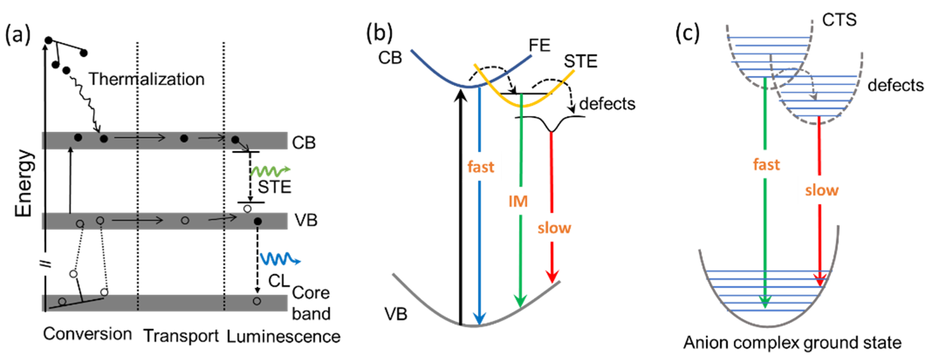
2. Scintillation Mechanism

The kinetics of the scintillation event is characterized by conversion, transport, and luminescence stages, as shown in Figure 1a, which are few orders slower than the initial energy conversion stage. For the single component decay, the emission intensity I(t) related to the decay time τ is the following:
I ( t ) = A e t τ
where A is a constant. The decay time can be characterized by the transition states or levels responsible for emitting the photons. Cross luminescence (CL) is one of the phenomena for fast scintillation with decay time in the order of a few nanoseconds or less, where the radiative transition occurs between an electron in the valence band, and a hole in the core band recombine (Figure 1a). The general requirement for CL is that the energy difference.
Ec-v between top of valence band and top of core band should be less than bandgap Eg (Ec-v < Eg) [16]. If, on the other hand, Ec-v > Eg, an Auger process occurs, which is non-radiative recombination of the core hole with the electron from the valence band. CL is often spotted in alkali halides and alkaline-earth halides [17]. Moreover, near band-edge emission via excitons or the charge transfer (CT) emission in anionic complexes, where metal ions coordinated by the anions (O2−, S, Se, F, Cl, Br, I), are two typical luminescence centers in self-activated scintillation materials (Figure 1b,c). Excitonic luminescence involves recombination of free electrons and free holes attracted to each other by Coulomb interaction, also known as free excitons, whereas a significant coupling between the free excitons and lattice generates a lattice distortion, causing self-trapped by the distortion, known as self-trapped exciton (STE) [18]. STE can be considered as excited-state defects, as they exist only upon excitation, and the lattice distortion disappears following decay to the ground state [19]. In general, the STE originated luminescence lifetime is of the order of few tens of ns to hundreds of ns (the intermediate process in Figure 1b). While the presence of lattice defects can trap either of the charge carriers (holes and electrons) and increases the decay lifetime, being the slow process in Figure 1b. CT scintillation is another kind of self-activated scintillation process, as shown in Figure 1c. Transition-metal and lanthanide ions in crystals and solutions exhibit broad absorption bands in the UV region, due to transition caused by the transfer of an electron from a ligand to the incomplete d or f shell of the ions. This kind of transition is termed as charge-transfer absorption. The reversed process, which transfers of the electron from the central ion back to the ligand, leads to an emission of a photon. Typical decay times for the CT luminescence are quick (ns). While in the presence of lattice defects, the decay time is longer.

3. Emission Dynamics in Inorganic Scintillators

The common inorganic scintillators include halides (alkali-metal halide, alkaline-earth halide, rare-earth halide, oxy-halide, rare-earth oxyorthosilicates, halide perovskite), oxides (binary oxide, complex oxide, post-transition metal oxide), sulfides, and rare-earth doped scintillators. The emission dynamics of these scintillator materials is presented in the following sections.

3.1. Emission Decay Dynamics in Halides

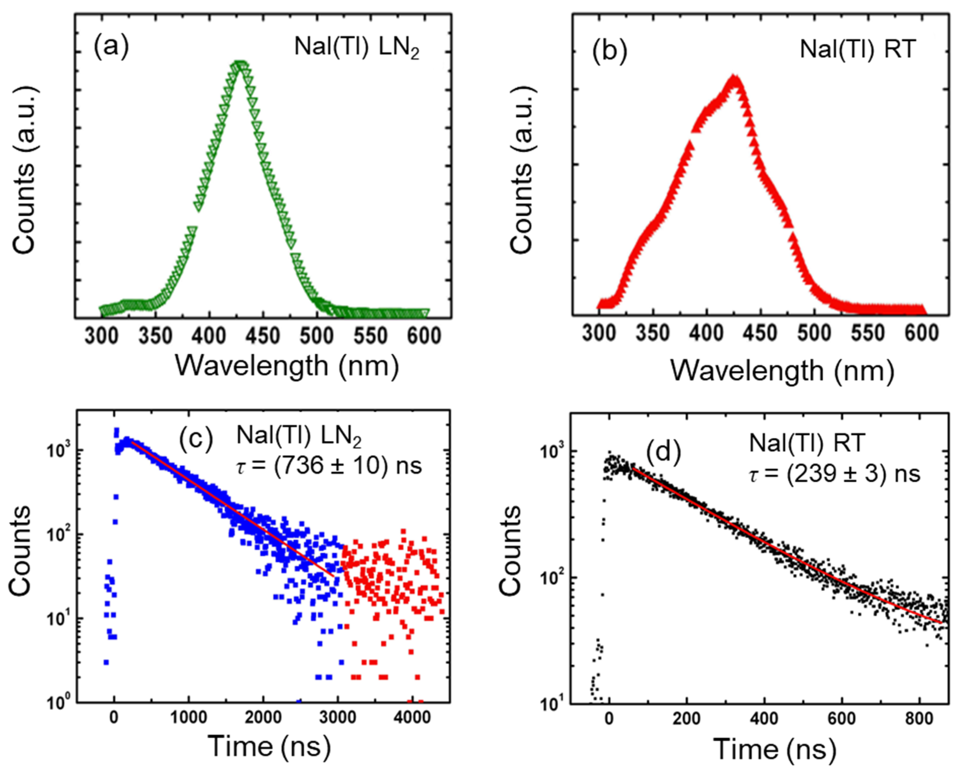
3.1.1. Alkali-Metal Halides

Activated alkali halide crystals are widely used as scintillation detectors for X-rays and γ-rays. The emission of undoped alkali-halides is mainly due to recombination of STE. In alkali halides and some other ionic crystals, there are self-trapped holes (Vk). The self-trapped holes are stable and remain localized at low temperatures whereas the electron mobilities are much higher [20]. Thus, the charge recombination dynamics is slow in alkali halides. In some pure alkali halides, luminescence at wavelength range of 400–500 nm can occur through generation of F-H centers formed due to electron-hole vacancies [21]. However, this type of emission has rather low intensity. Pure NaI [22] and pure CsI [23] have fast radiative recombination (few tens of ns) due to lattice intrinsic property. Schotanus et al. [24] observed two emission bands in pure CsI under X-ray excitation at 315 and 450 nm, respectively. The 315 nm maxima band was ascribed as STE luminescence of the pure CsI, whereas the 450 nm component was explained by the presence of I vacancies (lattice defects). The scintillation yield at room temperature (RT) is very low for both the materials; hence, in general, they are doped with an activator, especially with Tl+ ions [25]. However, at low temperature scintillation, a high light yield can be achieved by suppressing of non-radiative component [26,27]. For example, Moszyński and coworkers [28] reported light yield of 10,000 ph/MeV at 77 K for the pure CsI. However, pure NaI and pure CsI have limited utilization due to low light output at RT. Doping of Tl+ ions with a ns2 outer shell configuration in the lattices of NaI and CsI incredibly increases the light output at RT. NaI:Tl is one of the most common inorganic scintillators for many applications because of its very high light output of >44,000 photons per MeV. Minor doping with thallium (0.1%) in NaI(Tl) gives rise to a broadband at 430 nm (Figure 2a,b) attributed to Tl+ emission, while significantly lower light output was obtained when crystal was cooled down to liquid nitrogen (LN2) temperature, as reported by Sibczyński et al. [27]. Light output of NaI:Tl differs radically at liquid nitrogen (LN2) temperature and RT. The light yield at LN2 temperature was (9100 ± 450) e-h/MeV, which is almost a half the light output measured at RT (18,700 ± 930) e-h/MeV. Further, scintillation emission dynamic was also found to be different at the lower temperatures, and the decay time was measured as (736 ± 10) ns at LN2 and (239 ± 3) ns at RT, respectively (Figure 2c,d) [27]. There are some disadvantages associated with the NaI(Tl) that limit its application despite very high light yield, such as hygroscopicity and low strength against mechanical and thermal shocks [29]. Moreover, the major decay time of the scintillation is >200 ns, which is inadequately long for may fast or high counting applications. Although, highly pure NaI(Tl) scintillator with τ ~200 ns can be chosen for particle dark matter investigation due to well-known technology [30,31].

3.1.2. Alkaline-Earth Halides

Among alkaline-earth halides, the best-known fast scintillator is BaF2 (τ = 0.6 ns). The X-ray induced emission of BaF2 has fast and slow two components, as shown in Figure 3. The fast component has two maxima at ~190 and ~220 nm, with ultrafast decay time of 0.6 ns. In contrast, the slow component at a longer wavelength (250–400 nm), with decay time of ~620 ns [32]. The ultrafast intrinsic luminescence in BaF2 is due to radiative electronic transitions between the top core band (5p, Ba) and valence (2p, F) levels of the crystal (cross luminescence). The slow scintillation component in BaF2 is due to the relaxation of STE. Fast timing is required for positron lifetime studies, time of flight measurements, positron emission tomography, and several high energy or nuclear physics applications. BaF2 is a good choice for such an application. However, the slow component at 310 nm with a decay time of about ~600 ns, which causes deterioration of the time resolution at high counting rates. Suppression of the slow component is a crucial key when applying this material to high counting rate experiments. An approach for slow component suppression is lanthanide (Ln) doping into BaF2. Ln ions cause a significant reduction of the slow component with just a slight reduction of the fast component [33].
Schotanus and coworkers [33] found that the addition of a few percent of La3+ to the BaF2 substantially reduced slow component with no considerable effect on the intensity of the fast component. The suppression of the ~310 nm STE band in Ln doped BaF2 is due to energy transfer from STE band to the various excitation band of Ln3+ ions. Metal chlorides relatively have a less bandgap Eg than their fluorides counterparts. That is why only a few alkaline earth chlorides materials possess relatively bright cross luminescence. Like BaF2, barium chloride (BaCl2) also has a very fast decay component with a lifetime of 1.6 ns and a slow component of several tens of nanoseconds. However, Koshimizu et al. [35] reported the origin of the fast component as an attribute of self-trapped excitons, whereas the observed slow component was considered an extrinsic luminescence.

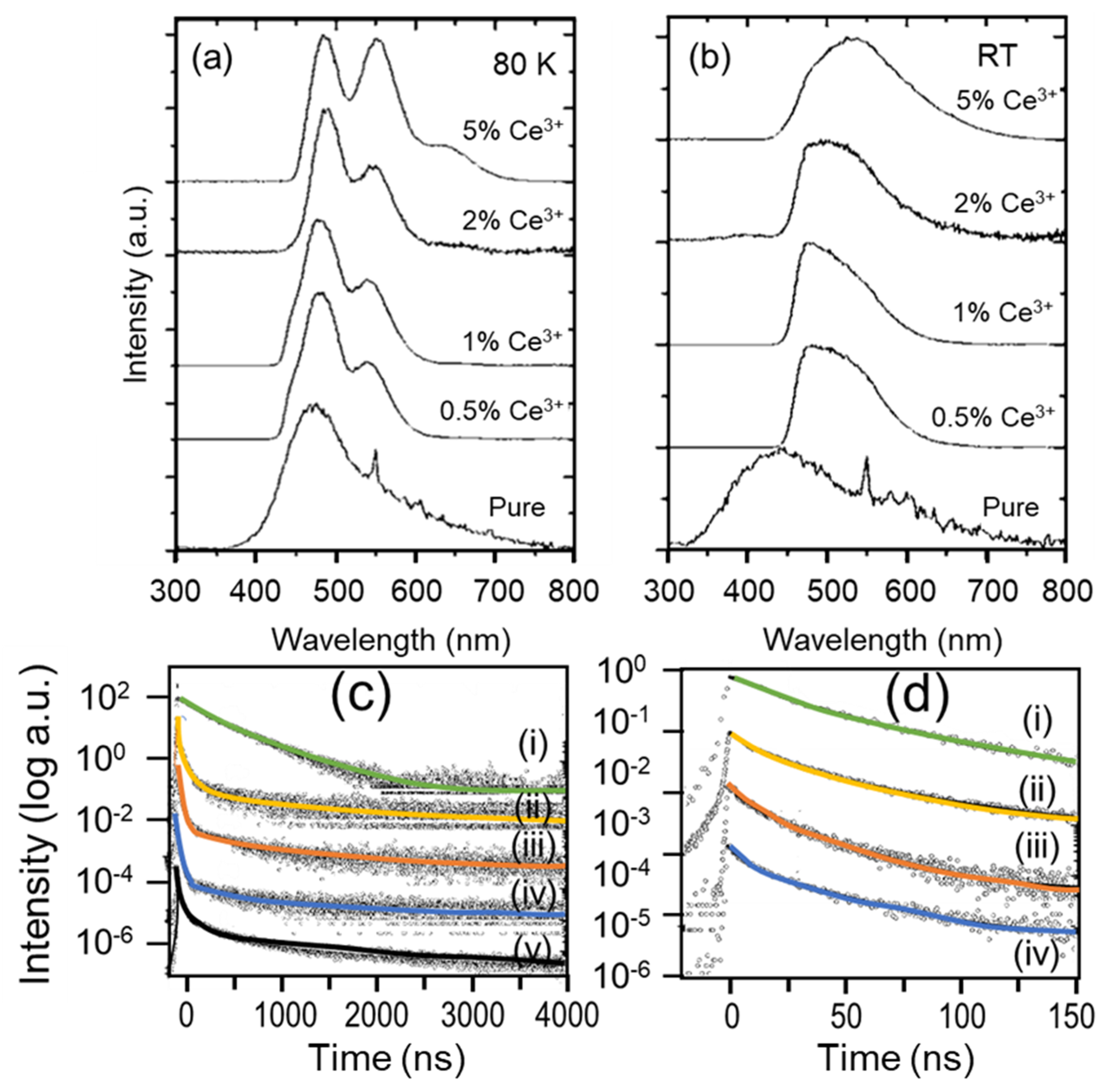
3.1.3. Rare-Earth Halides

RE halide scintillators are promising materials for X-rays and γ-rays detection. LuI3 compound has high atomic number and high density (5.6 g/cm3) that can be used to cause X-ray and γ-ray ceasing [36]. In a systematic study of the scintillation properties of pure and Ce3+ doped LuI3 materials, Birowosuto et al. [37] found them suitable for RT scintillation process. At both low temperature (80 K) and RT, radioluminescence spectra exhibited a broadband emission around ~470 and ~450 nm, respectively, for the undoped LuI3 sample (Figure 4a,b). This band is attributed to STE luminescence. Whereas Ce3+ doped (0.5%, 1%, 2%, and 5%) samples consist of two broad overlapping bands at 472 and 535 nm. These bands are attributed to Ce3+ luminescence and no residual of STE emission is present [38]. The scintillation decay curve of various Ce doped LuI3 samples has shown multiple time scale average decay time, as shown in Figure 4c,d. Ce3+ doping into the host introduced a faster decay component arising from direct electron-hole capture on the Ce3+ site. In undoped LuI3, the scintillation decay curve is dominated by two intermediate components of 199 and 550 ns, whereas, in Ce3+ doped samples, the scintillation decay curves exhibit a fast decay component of 35 ns. Additionally, an ultrafast component of 6–10 ns is observed in the scintillation decay time curves of LuI3:1%, 2%, and 5% Ce3+. LuI3: Ce3+ is a green-emitting scintillator at RT with promising photodiode application.
The alkaline-earth halides have excellent luminescent properties when various RE ions are doped into their lattice. Eu2+ activated alkaline-earth halides are good for the conversion of ionizing radiation into visible blue light. Figure 5 shows the beta-excited radioluminescence spectra of several alkaline-earth halide crystals, emitting in the blue region of the visible spectra. They show a typical Eu2+ emission in various alkaline-earth halide crystals that is due to Eu2+ df transition, and the decay time of such transitions is relatively long (μs). Eu2+ doped strontium iodide (SrI2:Eu2+) scintillator was discovered in 1964, and subsequently patented by Hofstadter in 1968 [39]. Due to high theoretical light yield of >90,000 photons/MeV with an energy resolution of about 2.6% at 662 keV [13], it has recognized as an excellent material for γ-ray spectroscopy [40]. CaI2:Eu2+ is another blue light-emitting halide with a higher theoretical light yield (114,000 photons/MeV) [40] than the SrI2. The crystal is prone to cracking and plastic deformation during both crystal growth and detector fabrication, and such defects are likely the reason why CaI2 has not been extensively explored [41]. For X-rays/γ-rays down conversion to blue light, SrI2:Eu2+ is the most promising among other alkaline-metal halides while its long (μs) Eu2+ lifetime is limited by its fundamental matrix component.

3.1.4. Oxy-Halides

Introduction of the halogen ions into conventional inorganic oxide compounds affects the electronic state of the metal center. With the substitution of oxygen anion by halogen with a different valence, ionic radius and bonding nature can be utilized for tweaking the scintillation properties of the compound. RE based oxy-halides are extensively studied for the scintillation application. The characteristic emission of the RE activator ions can be observed in RE based oxy-halides. Various cerium doped REOX (RE = Y, Gd, La, and Lu; X = F, Cl, Br, and I) oxyhalide compounds were studied by Eagleman et al. [43]. Of these materials, YOCl:Ce3+, GdOCl:Ce3+, and all oxybromides and oxyiodides showed typical cerium-activated emission with a decay time of 20–30 ns. The emission intensity of the RE activator ion in RE oxyhalide decreases as the stability of the phosphor decreases. The hygroscopic nature of each RE oxyhalide is inversely related to the ionic size of their rare earth. For the same reason, Rabatin [44] found lutetium oxyhalides compounds were much less stable compared to lanthanum oxyhalides, causing decrease in the phosphor light emission intensity. The RE oxyhalides provide an appropriate host matrix for lanthanide doping. For the Ce3+ ions, the emission wavelength changes with the halide in the composition. When an anion changes from Cl, Br to I, generally this change leads to a faster scintillation response, as the lifetime of STE shortens [14].

3.1.5. Rare-Earth Oxyorthosilicates

Lutetium oxyorthosilicate (Lu2SiO5, LSO) and yttrium oxyorthosilicate (Y2SiO5, YSO) are well known rare-earth oxyorthosilicates as scintillation materials [45]. Doping with rare-earth elements, LSO/YSO are competitive to other scintillating materials such as LuAlO3 perovskite or Gd3Ga4O12 garnets with submicron resolution [46,47]. Inorganic scintillators are widely applied to medical imaging scanners. LSO has large absorption coefficient, high light output, and fast decay [48]. LSO:Ce shows interesting properties such as high luminescence efficiency, high density of 7.4 g/cm3, and a fast decay time of ~40 ns [49]. However, it is well known that LSO:Ce exhibits an “afterglow” phenomenon, in which LSO crystals emit photons for several hours after irradiation by visible light or X-rays [50]. Short decay time is a desirable parameter for many applications, such as time-of-flight positron emission tomography since faster decay time substantially improves coincidence timing. Codoping with Ca divalent cations can influences the scintillation properties of LSO:Ce. Agnieszka et al. [50] found Ca2+ codoped LSO:Ce sample had increased light output of about 30% and the afterglow decay time shortens. Another work by Szczęśniak et al. [51] found that 0.3–0.4% Ca2+ shortened the decay time to ~30 ns. Codoping Mg2+ to Gd3Al2Ga3O12:Ce scintillating crystals also improved response time [52].

3.1.6. Halide Perovskite

Perovskites are an emerging class of materials exhibiting outstanding optoelectronic properties [53] in devices, such as solar cells, light-emitting diodes (LED), photodetectors and laser diodes [54]. Halide perovskite materials have the general formula ABX3, where A and B are two cations, and X is a halide such as I or Br [55]. These materials exhibit excitonic luminescence under X-ray excitation [55]. Replacing either A-site cation, B-site cations with different metal cations or X with different halogens, the scintillation properties can be tuned. The general scintillation mechanism for the high-intensity irradiation from the perovskite nanocrystals proposed by Chen et al. [56] is shown in Figure 6a. Upon X-ray irradiation, high-energy electrons are ejected from the lattice atoms through photoelectric ionization. Subsequently, the ejected high-energy electrons produce secondary electrons. The generated hot charge carriers then undergo thermalization and produce low-energy excitons. A recombination of the excitons in either a singlet (S) or triplet (T) state at the electronic band-edge produces fast scintillation (on the time scale of few ns to tens of ns.) [56]. Halide perovskites have efficient self-trapped excitons emission. The emission profile is often the same in halide perovskites under X-ray and UV light excitation, indicating that the dominant scintillation mechanism is similar under both source excitations [57]. Heo and coworkers studied the scintillating property of CsPbBr3 nanocrystal by examining the static and dynamic photoluminescence. The band-edge emission of CsPbBr3 was observed at 550 nm with an average lifetime of 2.87 ns [36], and similarly, Wang et al. [58] reported the average lifetime (τav) of CsPbBr3 nanosheets as 5.9 ns. The optical bandgap energy (hence the emission wavelength) can be tuned across almost the entire visible range (ca. 410–700 nm) by adjusting the halide composition due to the different ionization potentials of the various halide components (Figure 6c). The effect of change in halide component can be observed by monitoring the change in the solution appearance (Figure 6b). The emission wavelength has an inverse relation with the decay time, which can be modified. Tong and coworkers synthesized CsPbX3 (X = Cl, Br, I, Cl/Br, and Br, I) nanocrystals [59]. Time-resolved PL measurements of CsPbX3 nanocrystals (NCs) revealed multiexponential decay traces with average lifetime in the range of 2.5–34.5 ns and with an inverse correlation between the halide-ion-controlled bandgap and the decay lifetime (Figure 6d). Replacing lead with nontoxic metals tin, Jellicoe et al. studied the Sn-based metal halide perovskite (CsSnX3) PL kinetics and observed two distinct decay components [60]. The fast-decaying luminescence was described from band-edge states, while the slower decay was due to recombination from defects states just below the band-edge. Metal halide perovskite can convert X-rays directly into visible emission. The light yield which is a vital factor to consider when choosing a scintillator is inversely proportional to the optical bandgap (Eg). Metal halide perovskites generally have low bandgap (1.6–3.1 eV) compared to traditional scintillators (CsI = 6.4 eV, NaI = 5.9 eV, CaWO4 = 4.6 eV) [61]. Thus, halide perovskites offer higher theoretical yield ~130,000–250,000 photons/MeV [62] along with easy synthesis of low-dimensional structures with straightforward control on the dynamics of the recombination [57].
Fluorides, chlorides, and bromides containing cations with the binding energy of electrons of outermost np6 shell from 12 to 19 eV normally have Ec-v < Eg [63]. The condition is met for the CL in Ba, Cs, Rb, and K based crystals, which is an ultra-fast emission process. The origins of STE luminescence and CT luminescence are fundamentally different from CL; STE occasionally appears as a slow component in the decay profile. To achieve ultra-fast luminescence, alkaline-earth halides are preferred over alkali halides because of their non-hygroscopic property, whereas doped alkali-metal halides offer higher light yield over the alkaline-earth halides. The band structure of a halide inorganic materials changes with the alteration in halide anion, hence causing the origin and decay time of the scintillation change. Table 1 lists various halides and their scintillation characteristics.

3.2. Emission Decay Dynamics in Oxides

3.2.1. Binary Oxides

Inorganic ionic crystal and wide bang-gap semiconductors show band to band transition. For intrinsic semiconductors, recombination kinetics is a complex function dependent on the radiative recombination rate, photoexcited charge carrier density, interactions among these photoexcited carriers (e.g., Coulomb interactions), and interactions with the defects (e.g., nonradiative recombination) and the lattice [64]. The excitonic transitions in a semiconductor display sub-nanosecond radiative lifetimes. The spontaneous emission probability (1/τ), also called “Einstein A coefficient” [65]:
1 τ = 4 e 2 3 c 3 ω 21 3 | r 21 | 2
where is ħ Planck’s constant, c the velocity of light, ω the angular frequency of the radiation, r21 is the dipole matrix element. The dependence of τ on the ω3 factor for the X-ray spectral range can lead to an extremely fast radiative lifetime (ps) [66]. Some oxide materials are listed in Table 2.
ZnO:Ga showed near-band-edge emission (NBE) under X-ray excitation [97]. The scintillation light yield in semiconductors is often low, due to competing non-radiative channels at RT. Ga n-type impurities in ZnO provide an abundant supply of electrons as additional radiative centers. Lehmann [97] suggested two models to explain the ultra-fast NBE emission of ZnO:Ga at RT. These were (1) the recombination of donor band electrons (from the introduction of the gallium) and free holes in the valence band (created as a result of the excitation) and (2) the recombination of donor band electrons and holes trapped in a level close to the valence band-edge (shallow acceptors) (Figure 7a). Likewise, a p-type impurity can act as a hole trap, increasing the probability of the radiative recombination in the crystal. The addition of tellurium in zinc selenide as an isovalent impurity introduces defect centers serving for efficient recombination centers [98]. With addition of both types of impurities (n-type and p-type), one serves as an efficient electron donor, and another one provides efficient trapping of the holes respectively, which can be a possible strategy to achieve a luminosity and decay time close to the fundamental limits [99]. Whereas, the other lattice defect assisted emission can be very long (μs), as reported for ZnO:Zn, CdS:Ag and ZnS:Ag [100].
β-Ga2O3 is a wide bandgap (4.85 eV) [101] scintillator with very fast decay time. He et al. [102] investigated the PL and scintillation properties of this semiconductor material. The emission profile under ultraviolet excitation and X-ray excitation was basically the same, concluding the existence of similar decay channels. Yanagida and coworkers [81] report the scintillation properties of β-Ga2O3 as shown in Figure 7b,d. The emission band is mainly composed of two peaks in the UV and blue ranges. The emission band peak centered at 380 nm has a complex character, which is a characteristic for a system where transitions occur within different emission centers [103]. The UV band is generally independent of specific impurities and thus is assigned to the emission of STE [104]. This emission mechanism is different from the NBE emission, which can cause unavoidable self-absorption, due to small Stokes shift. The UV band emission typically demonstrates fast kinetics in the nanosecond range. The broad blue band is attributed to transitions involving deep donors and acceptors. Electrons recombining with holes at the defect sites are the origin of recombination luminescence with long decay kinetics (hundreds of ns range). The two emission centers can be seen in the decay curve (Figure 7c) that consists of two exponential components with time constants of 8 and 977 ns. The scintillation properties of the crystal can be enhanced by certain doping. Ions with ns2 outer shells are well known luminescent centers with intense inter-configuration transitions (s2 → sp) [105,106]. Tl+, Pb2+, Bi3+ with 6s2 are all in this class that has been used as luminescent centers for the scintillation process. The mixing of singlet and triplet excited states is due to spin-orbit interaction, and the decay time is short. The luminescence decay time is of the order of hundreds of μs at low temperatures, but it is diminished by many orders of magnitude (hundreds of ns) at RT by temperature quenching [2]. Several ns2 ions were doped in β-Ga2O3 crystal by Usui et al. [107]. The impact onto the scintillation decay time is shown in the form of a Table 3. Doping of the ns2 ions showed higher scintillation intensities than that of the undoped crystal. Generally, emissions due to ns2 ions appear around 400–600 nm which overlap with the host emissions. Moreover, the transitions among nsnp–ns2 of the dopant ions have different characteristics than the host β-Ga2O3. Thus, the emission intensity and radiative decay time change with such dopants. More reports on binary oxides can be found in the literature [108,109].

3.2.2. Complex Oxides

Charge-transfer emission of a photon in multi-metal crystal system and solutions typically has quick decay times (ns). While in the presence of lattice defects, the decay time gets longer. Lead tungstate (PbWO4) is an example of a self-activated scintillator with a fast emission of charge-transfer transitions in anionic molecular complexes. It typically shows two broadband emission: one in the blue region and another in the green region (other emissions due to lattice defects are neglected here). The blue emission is usually attributed to the STE recombination at the regular host oxy-anionic complexes (WO4)2−, and the green emission band is attributed to STE recombination at oxygen-deficient oxy-anionic complexes WO3 [110,111]. As previously discussed (Figure 1c), the allowed transition between CTS and the ground state is usually very fast. Anionic complexes have the highest occupied molecular orbitals, which are formed by the anions 2p orbitals and is separated from the first excited state that is made up mainly of metal d orbitals. The emission from CTS is fast. In many investigations, the characteristic luminescence decay time in PbWO4 single crystals was found 8–10 ns [110,112,113]. CaWO4 and CdWO4, the other two tungstate compounds, have similar intrinsic luminescence of excitonic nature as PbWO4, but their decay rates are different at RT. The decay time of CaWO4 or CdWO4 is in the order of several μs, whereas of PbWO4, in the order of nanoseconds. There is a significant difference in thermal stability and the onset of thermal quenching of the excitonic state [114]. For the detail of creation and stability of the excitons in PbWO4, refer to a report by Laguta and coworkers [115]. In CaWO4 and CdWO4, STE emission intensity was temperature-independent almost up to RT, while STE in PbWO4 started thermally reducing around 150 K and become critically thermally quenched at RT, leading to faster decay time and much lower scintillation efficiency [116].
Recently, charge transfer type luminescence of different metal-tantalate-oxides including ScTaO4, YTa3O9, and Zn3Ta2O8 have been analyzed by Bourret and coworkers [117]. The comprehensive study of over 63 metal-tantalate-oxides shed light on the effect of Ta-O-Ta angle in the local crystal structure of the metal-tantalate-oxides. In their report, only three compounds (ScTaO4, YTa3O9, and Zn3Ta2O8) are found to have 40% of their emission in the first 1 μs along with light yield greater than 1000 ph/MeV at RT. The origin of luminescence in tantalate compounds is mainly attributed to the recombination of STE, on a tantalate group (Ta4+–O2−). Difference of the excitonic luminescence intensity among the compounds was interpreted in terms of crystal structure/self-trapping energy relationship [118,119]. The smaller the Ta-O-Ta angle, the higher the luminosity. Bourret et al. [117] concluded pure Zn3Ta2O8 is the best among metal-tantalate-oxides with estimated luminosity of 26,000 ph/MeV with a decay time of approximately 600 ns.

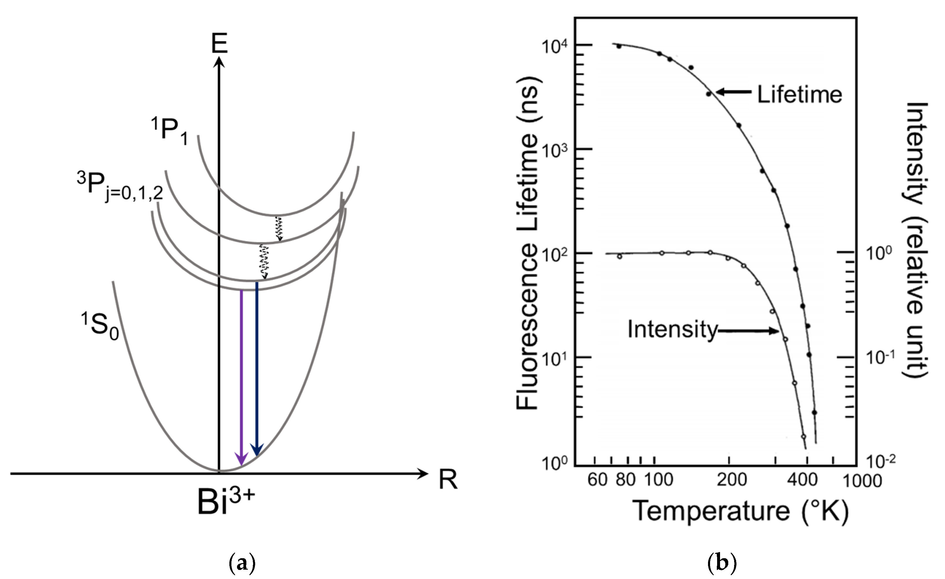
3.2.3. Post-Transition Metal Complex

Bismuth germanate, mostly expressed as Bi4Ge3O12 (BGO), is a complex inorganic material composed of elements following transition elements. It is a typical example of bismuth synthetic material with ρ = 7.1 g/cm3, and the high density offers good attenuation of X-rays and low radiation damage, resulting in good reproducibility of the detection. BGO single crystal under X-ray excitation is characterized by a short decay time (300 ns) and an extremely small afterglow [120]. Trivalent bismuth cation in inorganic compounds or hosts exhibits interesting luminescence properties originating from the excitation and emission of its 6s2 inert lone pair electrons [121,122]. Bismuth ion (Bi3+) emission spectra show a broadband due to electron transition between the 6s2 ground states and the 6s6p excited states [123]. The transition between the ground state of Bi3+ ion (1S0) and its excited triplet levels (3P0 or 3P2) [124] is spin forbidden; however, the excited 3P1 level undergoes mixing with the singlet 1P1 level by spin-orbit coupling, allowing 1S03P1 transitions. Radiative transition from 3P11S0 is partially allowed, and the decay time usually is between 10−6 to 10−8 s [125]. For instance, Blasse et al. found LaBO3:Bi3+ and CaSO4:Bi3+ with lifetimes of 800 ns and (60 ± 10) ns, respectively [125,126]. Radioluminescence decay of BGO at different temperatures was found in the range of 6 ms to 300 ns by Porter-Chapman and coworkers [127]. Weber and Monchamp [128] associated BGO PL and radioluminescence to Bi3+ transitions (Figure 8a). The emission levels are closely spaced, and the population in the excited level varies with the temperature, and hence, the decay time is a function of temperature (Figure 8b). At low temperatures, emission deriving from 3P01S0 has a long decay time (μs) due to the small probability of this transition. At higher temperatures, the luminescence appears mainly from the partially allowed transition (3P11S0) with a shorter decay time (hundreds of ns). The shorter decay times observed at higher temperatures are also attributed to non-radiative quenching commonly found in Bi3+-activated materials [127].
The popularity of BGO as scintillator encouraged research in the field of other Bi3+ doped compounds. Such studies on three Sillen bismuth oxyhalide phases, SrBiO2Cl, BaBiO2Br, and BaBiO2Cl, have shown varying scintillation properties in term of light yield and temperature dependency. In a comparative study of SrBiO2Cl, BaBiO2Br, and BaBiO2Cl with BGO, Porter-Chapman et al. [127] found the X-ray excited luminosities of the three compounds to be 24%, 27%, and 81%, respectively, of the BGO luminosity. A complete listing of the three major decay components and their fractional percentages for SrBiO2Cl, BaBiO2Br, BaBiO2Cl, and BGO measured at RT can be found in Table 4. SrBiO2Cl displays relatively fast decay times of 50, 200, and 300 ns at RT for its most significant decay components, when compared to the other two Sillen compounds and BGO. Moreover, the radioluminescence observed in BaBiO2Br and BaBiO2Cl is not as temperature dependent in comparison to the luminosities found in SrBiO2Cl and BGO. There are more research reports on the doped BGO [96,129,130,131,132].

3.3. Emission Decay Dynamics in Sulfides

Semiconductor scintillators have both excellent luminosities and the shortest decay times. In this section, scintillation properties of sulfide semiconductors are discussed. ZnSe:Te and CdSe:Te are examples of two commercially available sulfide scintillator. Tellurium is used as an isoelectric hole trap [133]. Tellurium has an electronegativity of 2.1 eV and acts as a hole trap when it replaces Zn or the Cd in the respective sulfide. Cadmium sulfide is a n-type direct-gap semiconductor. In 1966, Lehmann reported ultrafast (<1 ns) NBE emission from In-doped CdS [97]. The intensity was moderate at low temperatures and low at RT. CdS:Te has a broad emission spectrum with a maximum at ~640 nm (1.94 eV), 0.55 eV from the 2.49 eV band edge, and the main decay components are 270 ns and 3.0 μs [134]. At RT, configurational thermal quenching reduces the luminosity.
Silver-activated zinc sulfide is considered for fast neutron detection. ZnS:Ag,Cl is a commercial phosphor with an emission peak at 450 nm. It is a well-studied phosphor and the high luminosity (100,000 photons/MeV) [135] is attributed to a donor–acceptor complex that is very efficient in trapping ionization electrons and holes [136,137,138]. Many combinations of dopants and codopants have been reported, while the highest luminosity is achieved by using Ag (an acceptor) and Cl (a donor) as the codopant. The main drawback of the ZnS(Ag) phosphor has been its long decay time (~10−5 s) [139,140,141]. However, ZnS:Ag,Cl can be used to detect thermal neutron if a lithium compound enriched with 6Li is incorporated [142].

3.4. Rare-Earth Doped Scintillators and Refractive Index and Matrix Effect

RE-doped inorganic scintillators present wide optical tunability over the emission color. The 4fn–4fn−1 5d1 optical transitions have high radiative probability and short lifetime (tens of nanoseconds) when compared to parity forbidden ff transitions [143]. RE ions doping into a host matrix, e.g., fluoride, phosphate, oxide, and oxysulfide, generally exhibits their characteristic emission [144,145,146]. In RE-doped inorganic scintillators, primarily have three decay channels, which determines the scintillation emission dynamics (Figure 9). The fast decay (ns) is often associated with the 5d–4f emission of the rare-earth activator after sequential capture of the holes and the electrons during ionization. For the intermediate decay (few hundred of ns), the particles are firstly captured at the various impurity levels, leading to a prolonged lifetime. Whereas the slow decay (up to μs) can be either due to STE emission of the host or/and the non-radiative energy transfer from STE to the activator, resulting in direct radiation from the activator [147].
Ce3+, Pr3+, and Nd3+ are the common RE activator ions where the scintillation emission is due to dipole allowed transition from the lowest 4fn−15d1 to the 4fn ground configuration. Moreover, the absence of high-lying excited 4f states just below the 5d excited state in these activators reduces the probability of non-radiationally transfer of the excitation energy to the 4f states. A forbidden 4f–4f transition results in a longer decay (ms). In an ideal scintillator, the transfer speed of excitation energy from the ionization trail to the activator is much faster than the lifetime of the activator emitting state. Generally, the decay time rate Γ of an excited state is given by [135],
Γ = 1 τ n λ e m 3 ( n 2 + 2 3 ) 2 f | < f | μ | i | > 2
where n is the refractive index of the crystal and λem the emission wavelength, f and i denote the final and initial states, respectively, and µ is the dipole operator. The dipole operator µ is effective for transitions between states of different parity. The change in the decay time rate of RE-doped scintillators can be predicted following Equation (3). The decay time can be shortened by reducing the emission wavelength (λem) and increasing the refractive index (n). Following Equation (3), Dorenbos has predicted the decay time as a function of the refractive index n of the host compound for Ce3+ emission (Figure 10) [148]. Ce3+ ion emission is at 266 nm for KMgF3 (n = 1.4 and τ = 20 ns) whereas, the Ce3+ ion emission is at 314 nm for CaF2 (n = 1.43 and τ = 48 ns). The fluorides did not show decay time shorter than 20 ns. The refractive index needs to be larger than 1.6 to arrive at shorter decay times. Oxide compounds generally have larger refractive index (1.6 to 2.0) than fluorides, but the emission wavelength is longer as well; for example, λem = 535 nm for Y2Al3O12 with (n = 1.4 and τ = 62 ns), and λem = 345 nm for YAlO3 with (n = 1.96 and τ = 17 ns). The same applies to chloride and bromide compounds. The ultimate scintillation decay time for a RE- doped inorganic compound is limited by the host refractive index along with the activator’s emission wavelength.
The electric dipole matrix element for the fd transition decreases through the lanthanide series partly by a decrease of the overlap integral <f|µ|i> [149]. The radiative transition probability is proportional to the square of the overlap integral (Equation (3)) [150]. The average decay time of different RE ions doped hosts can be estimated assuming other factors the same for the same host lattice. For instance, the decay time of Ce3+ and Pr3+ doped in the same compound can be estimated employing Equation (3). The highest energy Pr3+ 5d–4f emission is always at 1.55 eV, a higher energy than the emission of Ce3+ 5d to its ground state [151]. Assuming the matrix elements are the same, the decay rate of Pr3+ emission to the ground state should be 0.4 times that of Ce3+ for Ce emission at 310 nm. The reported decay time of Pr3+in Lu3Al5O12 is 17.5 ns [38], and for Ce doped Lu3Al5O12, it is 52 ns [152]. Nearly the same as predicted by Equation (3). Whereas the matrix element of the divalent europium (Eu2+) is about a factor of 25 times smaller than that of Ce3+. The shortest scintillation decay for Eu2+ doped compounds is expected ~375 ns (~25 × 15 ns, and the Ce3+ decay time is 15 ns) [148].
Like transition metals, RE ions in crystals show absorption band in UV region due to a transition caused by the transfer of an electron from a ligand to the incomplete f or d shell of the RE ions [153,154,155]. Yb3+ doped crystals exhibit charge transfer luminescence in the visible and UV regions [156]. Nakazawa firstly observed charge transfer luminescence of the Yb3+ ion in 1977 in phosphate and oxysulfide lattices [156]. Yb3+ has only one excited state (2F5/2) located at 10,000 cm−1 above the ground state (2F7/2), and the energy difference between CT state and the highest 4f Yb3+ is about 39,000 cm−1 [157,158,159]. Transition from CT state to either the 2F5/2 or to 2F7/2 is expected to have a short lifetime (a few to a few tens of ns depending on the host). Fujimoto et al. reported decay times for Yb3+ doped YAG crystals in the range of 2–4 ns [160]. In a report by Pieterson and coworkers [161], recounted the time scale for the Yb3+ CT decay in various host (fluorides, oxides and oxysulfides) varies from 100 ns to 200 ns. Charge transfer luminescence mechanism is not inhibited by either the parity or by spin selection rules; hence it is fast (in the order of few ns to tens of ns).

4. Emission Dynamics of Organic-Inorganic Hybrid Scintillators

Organic-inorganic hybrid compounds have emerged as promising materials for various applications in optoelectronics and photovoltaic devices [162,163,164]. Such hybrid compounds have shown excellent scintillation properties, which can be easily tuned by selecting suitable organic and inorganic components. Further, the ease of synthesizing low-dimensional structure offers size confinement effect, causing to obtain enhanced scintillation properties. The effect of dimensionality and the organic sub-unit onto the scintillation properties are discussed as follows.

4.1. Effect of Dimensionality in Organic-Inorganic Hybrid Perovskites

The luminescence properties of the organic-inorganic hybrid compounds are dominated by the structural geometry of the inorganic layer [165]. Reducing the materials dimensionality modulates their optical properties. Recently, several scintillators of the lead-halide based perovskite-type organic-inorganic hybrid perovskites (OIHP) have been developed [166,167,168]. In these scintillators, fast light emission is caused by the excitons. Lead halide perovskite and organic ammonium layers based organic-inorganic hybrid compounds have a structure of alternating (PbX4)2− (X = Cl, Br and, I) and organic ammonium layers. This two-dimensional (2D) system show confinement in the direction to the layers [169]. The binding energy of excitons in a 2D system (quantum well) is four times greater than that in the corresponding 3D system (bulk) [170]. Due to the increasing overlap between electron and hole wave-functions in the 2D system, the oscillator strength increases, and the radiative lifetime decreases [171]. Kawano and coworkers investigated the scintillation property of (C6H5C2H4NH3)2 PbBr (Phe) organic-inorganic layered perovskite compound for γ-ray detection [171]. The compounds have self-organized multiple quantum well structures with alternating organic-inorganic layers [172]. The optical properties under optical and ionization irradiation were regulated by excitonic properties in the inorganic layer. The lifetime of exciton emission Phe was very fast (11 ns) (Figure 11a) along with very high scintillation light yield (14,000 photons per MeV), which was higher than the commercial organic-inorganic hybrid scintillator, such as BC-452. Similarly, Birowosuto et al. [57] compared the scintillation property of 3D MAPbI3 and MAPbBr3 (where MA = CH3NH3) and 2D 2,2′-(ethylenedioxy)bis(ethylammonium) tetrachloroplumbate (EDBE) PbCl4 organic-inorganic hybrid perovskite (Figure 11c,d). The X-ray excited luminescence and photoluminescence spectra of MAPbI3, MAPbBr3, and (EDBE)PbCl4 crystals recorded at RT are shown in Figure 11b. A similar emission profile indicated that the dominant scintillation mechanism was the same upon X-ray and optical irradiation, which is the intrinsic emission of near bandgap excitons. The decay kinetic study found the lifetime of the fastest component in the three compounds were 4.3 ns, 5.2 ns, and 7.9 ns, respectively. Due to charge confinement in 2D crystals within the inorganic layers had the larger exciton binding energy compared to 3D crystal. Under X-ray excitation, the 2D perovskite crystal was far more robust against thermal quenching (~9000 photon/MeV) than the 3D crystal <1000 photon/MeV) [173].
The organic–inorganic hybrid metal halide perovskite has the versatility in their chemical and crystallographic structures, and tunability in their physical properties. By designing proper components of the organic-inorganic halide perovskites, 0D, 1D, 2D, and 3D materials can be realized with different scintillation dynamic owing to change in the exciton binding energy and the oscillator strength. Therefore, the organic–inorganic hybrid crystals have great potential in fast scintillation applications at RT.

4.2. Effect of Organic Moieties on the Scintillation Properties of OIHP

The low dimensional structures of metal halide perovskites are advantageous over bulk counterparts due to their dielectric confinement effect, leading to an increased exciton binding energy and thus the strong luminescence. Particularly, the 2D layered hybrid structure is of great interest due to the organic moiety. The organic component in the OIHP causes various structural disorders that have a direct impact on the exciton decay time and the light yield. The Bohr radius of 1s 2D excitons can be expressed by the equation [165]:
a 0 2 D = 2 π 0 ε 2 m e 2
where m is the reduced mass of the excitons, and ε is the effective dielectric constant of the exciton. The Bohr radius of the excitons decreases with the increase in the reduced mass of the exciton (Equation (4)). The correlation between the Bohr radius of excitons and radiative decay rate (Γ0) of excitons with k = 0 in a quantum well can be expressed by the following equation [174]:
Γ 0 = 16 | μ c v | c ω a 0 2 2 ω 0 2
In Equation (5), μcv is the transition dipole moment, and ω is the energy of the excitons. According to this formula, the radiative decay rate increases with the decrease in the Bohr radius of excitons.
Kawano et al. [175] investigated the effect of structural distortion in three single crystals, namely, (C4H9NH2)2PbBr4(C4), (C6H5CH2NH2)2PbBr4 (Ben), and (C6H5C2H4NH2)2PbBr4 (Phe) on the Bohr radius and eventually on the decay rate. The luminescence properties of the hybrid compound can be governed by both structural distortions in the adjoining PbBr62− octahedra and inside the PbBr62− octahedron in the A2PbBr4 inorganic layer (A = organic component). Figure 12a shows the structural geometry between the adjoining PbBr62− octahedron, and Figure 12b shows structural geometry inside the PbBr62− octahedron. In a nutshell, the Pb-Br-Pb bond angle of Ben and Phe is less than C4. The transfer integral between adjoining atoms depends on the overlap integral of the valence band orbitals [176]. Band calculation demonstrated the narrow bandwidth in 2D crystals [177] because of structural distortion, resulting in a large effective mass of electrons and holes, which lead to a large reduced mass of excitons. Further, Phe also exhibits structural distortion inside the PbBr62− octahedron [165]. These structural distortions in the inorganic layer should increase light yields in scintillation since the reduced mass of the excitons increases, and Bohr radius of the excitons decreases by the structural distortion (Equation (5)) [178]. Figure 12c shows the decay profile of the three OIHP single crystals with the different organic moieties (C4, Ben and, Phe). The compounds under X-ray radiation had a lifetime of 1.1 ns (C4), 2.8 ns (Ben), and 9.6 ns (Phe). These results indicate that the scintillation lifetime varied when organic moieties were substituted, in the same order of the distortion in the three crystals (Phe > Ben > C4).
The scintillation properties of organic–inorganic layered compounds can be controlled by varying the types of organic moieties. This is because the geometric structure of the organic layers influences the structures in the inorganic layers, causing a change in the excitonic properties of the inorganic layer.

5. Summary

In this paper, the decay mechanisms of common inorganic scintillators are reviewed, including three major types of cross luminescence emission, excitonic emission, and dopant-based emission. Fluorides generally have larger bandgaps than the chlorides and oxides counterparts, showing higher scintillation yields and, hence, are ideal choices for the fast cross-luminescence process. Halide perovskites, AMX3, are self-activated scintillators exhibiting excitonic emission. The exciton emission wavelength can be easily tuned by exchanging the individual components and thus, offering controls over the scintillation lifetime.
Dopant-activated scintillators are a broad category with several kinds of luminescent centers, and their corresponding decay time is different. Ions with s2 outer shells, such as Tl+, Pb2+, Bi3+ ions in alkali halides and oxide compounds, have faster decay at RT, due to temperature quenching and mixing of singlet and triplet excites states by spin-orbit coupling. Selected RE ions can acts as fast emitting luminescent centers due to their parity, and spin allows optical transitions between 4f–5d states. Pr3+ and Ce3+ ions have decay time in the order of few tens of ns, whereas Eu2+ has decay time in the order of few hundreds of ns due to the lower matrix component. Additionally, the host matrix refractive index affects the decay time of the RE ion. Refractive index has an inverse relation with τ. Increasing the refractive index from fluorides to oxides and sulfides may decrease the average lifetime of the phosphor.
Dimensionality has a direct impact on the excitons binding energy and oscillator strength, due to the quantum confinement effect. Organic–inorganic hybrid compounds combine their facile synthesis of the low-dimensional structures (0D, 1D and 2D) with tunable optical properties. The confined excitons in the inorganic layers of the low-dimensional structures display increased scintillation.

Author Contributions

V.K. wrote this review article, and Z.L. supervised this research and revised the manuscript. All authors have read and agreed to the published version of the manuscript.

Funding

This research was funded by the US National Science Foundation (NSF) ECCS 1900837.

Institutional Review Board Statement

Not applicable.

Informed Consent Statement

Not applicable.

Data Availability Statement

The data presented in this study are available on request from the corresponding author.

Acknowledgments

The authors acknowledge the support from the Excellence in Research Program, Division of Electrical, Communications and Cyber Systems (ECCS), National Science Foundation.

Conflicts of Interest

The authors declare no conflict of interest.

References

  1. Pidol, L.; Kahn-Harari, A.; Viana, B.; Ferrand, B.; Dorenbos, P.; de Haas, J.T.M.; van Eijk, C.W.E.; Virey, E. Scintillation Properties of Lu2Si2O7:Ce3+, a Fast and Efficient Scintillator Crystal. J. Phys. Condens. Matter 2003, 15, 2091–2102. [Google Scholar] [CrossRef]
  2. Lecoq, P.; Gektin, A.; Korzhik, M. Inorganic Scintillators for Detector Systems: Physical Principles and Crystal Engineering, 2nd ed.; Particle Acceleration and Detection; Springer International Publishing: Berlin/Heidelberg, Germany, 2017; ISBN 978-3-319-45521-1. [Google Scholar]
  3. Shepherd, J.A.; Gruner, S.M.; Tate, M.W.; Tecotzky, M. Study of Afterglow in X-Ray Phosphors for Use on Fast-Framing Charge-Coupled Device Detectors. Opt. Eng. 1997, 36, 3212–3222. [Google Scholar] [CrossRef]
  4. Neitzel, U. Status and Prospects of Digital Detector Technology for CR and DR. Radiat. Prot. Dosimetry 2005, 114, 32–38. [Google Scholar] [CrossRef]
  5. Barabash, A.S.; Belli, P.; Bernabei, R.; Cappella, F.; Caracciolo, V.; Cerulli, R.; Danevich, F.A.; Marco, A.D.; Incicchitti, A.; Kasperovych, D.V.; et al. Low Background Scintillators to Investigate Rare Processes. J. Instrum. 2020, 15, C07037. [Google Scholar] [CrossRef]
  6. Pizzichemi, M. The Phase II Upgrade of the LHCb Calorimeter System. J. Instrum. 2020, 15, C05062. [Google Scholar] [CrossRef]
  7. Luo, Z.; Moch, J.G.; Johnson, S.S.; Chen, C.C. A Review on X-Ray Detection Using Nanomaterials. Curr. Nanosci. 2017, 13, 364–372. [Google Scholar] [CrossRef]
  8. Sailer, C.; Lubsandorzhiev, B.; Strandhagen, C.; Jochum, J. Low Temperature Light Yield Measurements in NaI and NaI(Tl). Eur. Phys. J. C 2012, 72, 2061. [Google Scholar] [CrossRef] [Green Version]
  9. Chen, C.C.; Chang, S.F.; Luo, Z. Anodic-Aluminum-Oxide Template Assisted Fabrication of Cesium Iodide (CsI) Scintillator Nanowires. Mater. Lett. 2013, 112, 190–193. [Google Scholar] [CrossRef]
  10. Shi, C.; Kloiber, T.; Zimmerer, G. Time Resolved Spectra of Intrinsic Emissions from Crystalline BaF2. Phys. Scr. 1990, 41, 1022–1024. [Google Scholar] [CrossRef]
  11. George, G.; Edwards, C.S.; Hayes, J.I.; Yu, L.; Ede, S.R.; Wen, J.; Luo, Z. A Novel Reversible Fluorescent Probe for the Highly Sensitive Detection of Nitro and Peroxide Organic Explosives Using Electrospun BaWO4 Nanofibers. J. Mater. Chem. C 2019, 7, 14949–14961. [Google Scholar] [CrossRef]
  12. Srivastava, A.M.; Happek, U.; Schmidt, P. Luminescence of LuCl3:Pr3+ under Interconfigurational (4f2→4f15d1) and Band Gap Excitations. Opt. Mater. 2008, 31, 213–217. [Google Scholar] [CrossRef]
  13. Boatner, L.A.; Ramey, J.O.; Kolopus, J.A.; Hawrami, R.; Higgins, W.M.; van Loef, E.; Glodo, J.; Shah, K.S.; Rowe, E.; Bhattacharya, P.; et al. Bridgman Growth of Large SrI2:Eu2+ Single Crystals: A High-Performance Scintillator for Radiation Detection Applications. J. Cryst. Growth 2013, 379, 63–68. [Google Scholar] [CrossRef]
  14. Dorenbos, P. Scintillation Mechanisms in Ce3+ Doped Halide Scintillators. Phys. Status Solidi A 2005, 202, 195–200. [Google Scholar] [CrossRef]
  15. Nikl, M. Scintillation Detectors for X-rays. Meas. Sci. Technol. 2006, 17, R37–R54. [Google Scholar] [CrossRef]
  16. Shwetha, G.; Kanchana, V.; Vaitheeswaran, G. CsMgCl3: A Promising Cross Luminescence Material. J. Solid State Chem. 2015, 227, 110–116. [Google Scholar] [CrossRef]
  17. Van Eijk, C.W.E. Cross-Luminescence. J. Lumin. 1994, 60–61, 936–941. [Google Scholar] [CrossRef]
  18. Song, K.S.; Williams, R.T. Self-Trapped Excitons; Springer Series in Solid-State Sciences; Springer: Berlin/Heidelberg, Germany, 1993; ISBN 978-3-642-97432-8. [Google Scholar]
  19. Smith, M.D.; Connor, B.A.; Karunadasa, H.I. Tuning the Luminescence of Layered Halide Perovskites. Chem. Rev. 2019, 119, 3104–3139. [Google Scholar] [CrossRef]
  20. Murray, R.B. Energy Transfer in Alkali Halide Scintillators by Electron-Hole Diffusion and Capture. IEEE Trans. Nucl. Sci. 1975, 22, 54–57. [Google Scholar] [CrossRef]
  21. Rodnyi, P.A. Physical Processes in Inorganic Scintillators, 1st ed.; CRC Press: Boca Raton, FL, USA, 1997; ISBN 978-0-8493-3788-8. [Google Scholar]
  22. Sibczynski, P.; Moszyńsk, M.; Czarnacki, W.; Syntfeld-Każuch, A.; Schotanus, P. Further Study of Undoped NaI Scintillators with Different Purity. In Proceedings of the IEEE Nuclear Science Symposuim & Medical Imaging Conference, Knoxville, TN, USA, 30 October–6 November 2010; pp. 574–579. [Google Scholar] [CrossRef]
  23. Kubota, S.; Sakuragi, S.; Hashimoto, S.; Ruan, J. A New Scintillation Material: Pure CsI with 10 Ns Decay Time. Nucl. Instrum. Methods Phys. Res. Sect. Accel. Spectrom. Detect. Assoc. Equip. 1988, 268, 275–277. [Google Scholar] [CrossRef]
  24. Schotanus, P.; Kamermans, R. Scintillation Characteristics of Pure and Tl-Doped CsI Crystals. IEEE Trans. Nucl. Sci. 1990, 37, 177–182. [Google Scholar] [CrossRef]
  25. Moszyński, M.; Zalipska, J.; Balcerzyk, M.; Kapusta, M.; Mengesha, W.; Valentine, J.D. Intrinsic Energy Resolution of NaI(Tl). Nucl. Instrum. Methods Phys. Res. Sect. Accel. Spectrom. Detect. Assoc. Equip. 2002, 484, 259–269. [Google Scholar] [CrossRef]
  26. Payne, S.A.; Cherepy, N.J.; Hull, G.; Valentine, J.D.; Moses, W.W.; Choong, W.-S. Nonproportionality of Scintillator Detectors: Theory and Experiment. IEEE Trans. Nucl. Sci. 2009, 56, 2506–2512. [Google Scholar] [CrossRef]
  27. Sibczyński, P.; Moszyński, M.; Szczęśniak, T.; Czarnacki, W. Study of NaI(Tl) Scintillator Cooled down to Liquid Nitrogen Temperature. J. Instrum. 2012, 7, P11006. [Google Scholar] [CrossRef]
  28. Moszyński, M.; Balcerzyk, M.; Czarnacki, W.; Kapusta, M.; Klamra, W.; Schotanus, P.; Syntfeld, A.; Szawlowski, M.; Kozlov, V. Energy Resolution and Non-Proportionality of the Light Yield of Pure CsI at Liquid Nitrogen Temperatures. Nucl. Instrum. Methods Phys. Res. Sect. Accel. Spectrom. Detect. Assoc. Equip. 2005, 537, 357–362. [Google Scholar] [CrossRef]
  29. Holl, I.; Lorenz, E.; Mageras, G. A Measurement of the Light Yield of Common Inorganic Scintillators. IEEE Trans. Nucl. Sci. 1988, 35, 105–109. [Google Scholar] [CrossRef]
  30. Mikhailik, V.B.; Kraus, H. Performance of Scintillation Materials at Cryogenic Temperatures. Phys. Status Solidi B 2010, 247, 1583–1599. [Google Scholar] [CrossRef] [Green Version]
  31. Bernabei, R.; Incicchitti, A. Low Background Techniques in NaI(Tl) Setups. Int. J. Mod. Phys. A 2017, 32, 1743007. [Google Scholar] [CrossRef]
  32. Han, H.; Zhang, Z.; Weng, X.; Liu, J.; Guan, X.; Zhang, K.; Li, G. Development of a Fast Radiation Detector Based on Barium Fluoride Scintillation Crystal. Rev. Sci. Instrum. 2013, 84, 073503. [Google Scholar] [CrossRef]
  33. Schotanus, P.; Dorenbos, P.; van Eijk, C.W.E.; Lamfers, H.J. Suppression of the Slow Scintillation Light Output of BaF2 Crystals by La3+ Doping. Nucl. Instrum. Methods Phys. Res. Sect. Accel. Spectrom. Detect. Assoc. Equip. 1989, 281, 162–166. [Google Scholar] [CrossRef]
  34. Stefan, D.; Rainer, W.N.; Benjamin, W.; Reinhard, B. Readout Concepts for the Suppression of the Slow Component of BaF2 for the Upgrade of the TAPS Spectrometer at ELSA. J. Phys. Conf. Ser. 2015, 587. [Google Scholar] [CrossRef]
  35. Koshimizu, M.; Onodera, K.; Shibuya, K.; Saito, H.; Asai, K. Timing Property of Undoped BaCl2 Single Crystal Scintillator. J. Appl. Phys. 2009, 105, 114912. [Google Scholar] [CrossRef]
  36. Heo, J.H.; Shin, D.H.; Park, J.K.; Kim, D.H.; Lee, S.J.; Im, S.H. High-Performance Next-Generation Perovskite Nanocrystal Scintillator for Nondestructive X-Ray Imaging. Adv. Mater. 2018, 30, 1801743. [Google Scholar] [CrossRef]
  37. Birowosuto, M.D.; Dorenbos, P.; van Eijk, C.W.E.; Krämer, K.W.; Güdel, H.U. High-Light-Output Scintillator for Photodiode Readout: LuI3:Ce3+. J. Appl. Phys. 2006, 99, 123520. [Google Scholar] [CrossRef] [Green Version]
  38. Nikl, M.; Ogino, H.; Krasnikov, A.; Beitlerova, A.; Yoshikawa, A.; Fukuda, T. Photo- and Radioluminescence of Pr-doped Lu3Al5O12 Single Crystal. Phys. Status Solidi A 2005, 202, R4–R6. [Google Scholar] [CrossRef]
  39. Hofstadter, R.; O’Dell, E.W.; Schmidt, C.T. CaI2 and CaI2(Eu) Scintillation Crystals. IEEE Trans. Nucl. Sci. 1964, 11, 12–14. [Google Scholar] [CrossRef]
  40. Cherepy, N.J.; Hull, G.; Drobshoff, A.D.; Payne, S.A.; van Loef, E.; Wilson, C.M.; Shah, K.S.; Roy, U.N.; Burger, A.; Boatner, L.A.; et al. Strontium and Barium Iodide High Light Yield Scintillators. Appl. Phys. Lett. 2008, 92, 083508. [Google Scholar] [CrossRef] [Green Version]
  41. Boatner, L.A.; Ramey, J.O.; Kolopus, J.A.; Neal, J.S.; Cherepy, N.J.; Beck, P.R.; Payne, S.A.; Burger, A.; Rowe, E.; Bhattacharya, P. Advances in the Growth of Alkaline-Earth Halide Single Crystals for Scintillator Detectors. In Proceedings of the Hard X-Ray, Gamma-Ray, and Neutron Detector Physics XVI, San Diego, CA, USA, 18–20 August 2014; International Society for Optics and Photonics: Bellingham, WA, USA, 5 September 2014; Volume 9213, p. 92130J. [Google Scholar]
  42. Cherepy, N.J.; Payne, S.A.; Asztalos, S.J.; Hull, G.; Kuntz, J.D.; Niedermayr, T.; Pimputkar, S.; Roberts, J.J.; Sanner, R.D.; Tillotson, T.M.; et al. Scintillators With Potential to Supersede Lanthanum Bromide. IEEE Trans. Nucl. Sci. 2009, 56, 873–880. [Google Scholar] [CrossRef] [Green Version]
  43. Eagleman, Y.D.; Bourret-Courchesne, E.; Derenzo, S.E. Room-Temperature Scintillation Properties of Cerium-Doped REOX (RE=Y, La, Gd, and Lu; X=F, Cl, Br, and I). J. Lumin. 2011, 131, 669–675. [Google Scholar] [CrossRef] [Green Version]
  44. Rabatin, J.G. Luminescence of Rare Earth Activated Lutetium Oxyhalide Phosphors. J. Electrochem. Soc. 1982, 129, 1552. [Google Scholar] [CrossRef]
  45. Melcher, C.L.; Manente, R.A.; Peterson, C.A.; Schweitzer, J.S. Czochralski Growth of Rare Earth Oxyorthosilicate Single Crystals. J. Cryst. Growth 1993, 128, 1001–1005. [Google Scholar] [CrossRef]
  46. Martin, T.; Douissard, P.; Couchaud, M.; Cecilia, A.; Baumbach, T.; Dupre, K.; Rack, A. LSO-Based Single Crystal Film Scintillator for Synchrotron-Based Hard X-Ray Micro-Imaging. IEEE Trans. Nucl. Sci. 2009, 56, 1412–1418. [Google Scholar] [CrossRef]
  47. Zorenko, Y.; Gorbenko, V.; Konstankevych, I.; Grinev, B.; Globus, M. Scintillation Properties of Lu3Al5O12:Ce Single-Crystalline Films. Nucl. Instrum. Methods Phys. Res. Sect. Accel. Spectrom. Detect. Assoc. Equip. 2002, 486, 309–314. [Google Scholar] [CrossRef]
  48. Shimizu, S.; Kurashige, K.; Usui, T.; Shimura, N.; Sumiya, K.; Senguttuvan, N.; Gunji, A.; Kamada, M.; Ishibashi, H. Scintillation Properties of Lu0.4Gd1.6SiO5:Ce (LGSO) Crystal. IEEE Trans. Nucl. Sci. 2006, 53, 14–17. [Google Scholar] [CrossRef]
  49. David, S.; Michail, C.; Valais, I.; Nikolopoulos, D.; Kalivas, N.; Kalatzis, I.; Karatopis, A.; Cavouras, D.; Loudos, G.; Panayiotakis, G.S.; et al. Luminescence Efficiency of Lu2SiO5:Ce (LSO) Powder Scintillator for X-Ray Medical Radiography Applications. In Proceedings of the 2006 IEEE Nuclear Science Symposium Conference Record, San Diego, CA, USA, 29 October–1 November 2006; Volume 2, pp. 1178–1182. [Google Scholar]
  50. Syntfeld-Kazuch, A.; Moszynski, M.; Swiderski, L.; Szczesniak, T.; Nassalski, A.; Melcher, C.L.; Spurrier, M.A. Energy Resolution of Calcium Co-Doped LSO:Ce Scintillators. In Proceedings of the 2008 IEEE Nuclear Science Symposium Conference Record, Dresden, Germany, 19–25 October 2008; pp. 2744–2750. [Google Scholar]
  51. Szcześniak, T.; Moszyński, M.; Synfeld-Każuch, A.; Świderski, Ł.; Koschan, M.A.S.; Melcher, C.L. Timing Resolution and Decay Time of LSO Crystals Co-Doped With Calcium. IEEE Trans. Nucl. Sci. 2010, 57, 1329–1334. [Google Scholar] [CrossRef]
  52. Tamulatis, G.; Dosovitskiy, G.; Gola, A.; Korjik, M.; Mazzi, A.; Nargelas, S.; Sokolov, P.; Vaitkevičius, A. Improvement of Response Time in GAGG:Ce Scintillation Crystals by Magnesium Codoping. J. Appl. Phys. 2018, 124, 215907. [Google Scholar] [CrossRef]
  53. George, G.; Ede, S.R.; Luo, Z. Fundamentals of Perovskite Oxides Synthesis, Structure, Properties and Applications, 1st ed.; CRC Press: Boca Raton, FL, USA, 2020; ISBN 978-0-367-35448-0. [Google Scholar]
  54. Chen, H.; Wang, H.; Wu, J.; Wang, F.; Zhang, T.; Wang, Y.; Liu, D.; Li, S.; Penty, R.V.; White, I.H. Flexible Optoelectronic Devices Based on Metal Halide Perovskites. Nano Res. 2020, 13, 1997–2018. [Google Scholar] [CrossRef]
  55. Jena, A.K.; Kulkarni, A.; Miyasaka, T. Halide Perovskite Photovoltaics: Background, Status, and Future Prospects. Chem. Rev. 2019, 119, 3036–3103. [Google Scholar] [CrossRef]
  56. Chen, Q.; Wu, J.; Ou, X.; Huang, B.; Almutlaq, J.; Zhumekenov, A.A.; Guan, X.; Han, S.; Liang, L.; Yi, Z.; et al. All-Inorganic Perovskite Nanocrystal Scintillators. Nature 2018, 561, 88–93. [Google Scholar] [CrossRef]
  57. Birowosuto, M.D.; Cortecchia, D.; Drozdowski, W.; Brylew, K.; Lachmanski, W.; Bruno, A.; Soci, C. X-Ray Scintillation in Lead Halide Perovskite Crystals. Sci. Rep. 2016, 6, 1–10. [Google Scholar] [CrossRef] [Green Version]
  58. Wang, L.; Fu, K.; Sun, R.; Lian, H.; Hu, X.; Zhang, Y. Ultra-Stable CsPbBr3 Perovskite Nanosheets for X-Ray Imaging Screen. Nano-Micro Lett. 2019, 11, 52. [Google Scholar] [CrossRef] [Green Version]
  59. Tong, Y.; Bladt, E.; Aygüler, M.F.; Manzi, A.; Milowska, K.Z.; Hintermayr, V.A.; Docampo, P.; Bals, S.; Urban, A.S.; Polavarapu, L.; et al. Highly Luminescent Cesium Lead Halide Perovskite Nanocrystals with Tunable Composition and Thickness by Ultrasonication. Angew. Chem. Int. Ed. 2016, 55, 13887–13892. [Google Scholar] [CrossRef] [PubMed]
  60. Jellicoe, T.C.; Richter, J.M.; Glass, H.F.J.; Tabachnyk, M.; Brady, R.; Dutton, S.E.; Rao, A.; Friend, R.H.; Credgington, D.; Greenham, N.C.; et al. Synthesis and Optical Properties of Lead-Free Cesium Tin Halide Perovskite Nanocrystals. J. Am. Chem. Soc. 2016, 138, 2941–2944. [Google Scholar] [CrossRef] [Green Version]
  61. Blasse, G. Scintillator Materials. Chem. Mater. 1994, 6, 1465–1475. [Google Scholar] [CrossRef]
  62. Xie, A.; Nguyen, T.H.; Hettiarachchi, C.; Witkowski, M.E.; Drozdowski, W.; Birowosuto, M.D.; Wang, H.; Dang, C. Thermal Quenching and Dose Studies of X-Ray Luminescence in Single Crystals of Halide Perovskites. J. Phys. Chem. C 2018, 122, 16265–16273. [Google Scholar] [CrossRef]
  63. Rodnyi, P.A. Core–Valence Luminescence in Scintillators. Radiat. Meas. 2004, 38, 343–352. [Google Scholar] [CrossRef]
  64. deQuilettes, D.W.; Frohna, K.; Emin, D.; Kirchartz, T.; Bulovic, V.; Ginger, D.S.; Stranks, S.D. Charge-Carrier Recombination in Halide Perovskites. Chem. Rev. 2019, 119, 11007–11019. [Google Scholar] [CrossRef] [PubMed]
  65. Dexter, D.L. Theory of the Optical Properties of Imperfections in Nonmetals. In Solid State Physics; Seitz, F., Turnbull, D., Eds.; Advances in Research and Applications; Academic Press: Cambridge, MA, USA, 1958; Volume 6, pp. 353–411. [Google Scholar]
  66. Wilkinson, J.; Ucer, K.B.; Williams, R.T. Picosecond Excitonic Luminescence in ZnO and Other Wide-Gap Semiconductors. Radiat. Meas. 2004, 38, 501–505. [Google Scholar] [CrossRef]
  67. Laval, M.; Moszyński, M.; Allemand, R.; Cormoreche, E.; Guinet, P.; Odru, R.; Vacher, J. Barium Fluoride—Inorganic Scintillator for Subnanosecond Timing. Nucl. Instrum. Methods Phys. Res. 1983, 206, 169–176. [Google Scholar] [CrossRef]
  68. Shendrik, R.; Radzhabov, E. Absolute Light Yield Measurements on SrF2 and BaF2 Doped With Rare Earth Ions. IEEE Trans. Nucl. Sci. 2014, 61, 406–410. [Google Scholar] [CrossRef] [Green Version]
  69. Moszyński, M.; Gresset, C.; Vacher, J.; Odru, R. Properties of CsF, a Fast Inorganic Scintillator in Energy and Time Spectroscopy. Nucl. Instrum. Methods 1981, 179, 271–276. [Google Scholar] [CrossRef]
  70. Moszyński, M.; Allemand, R.; Laval, M.; Odru, R.; Vacher, J. Recent Progress in Fast Timing with CsF Scintillators in Application to Time-of-Flight Positron Tomography in Medicine. Nucl. Instrum. Methods Phys. Res. 1983, 205, 239–249. [Google Scholar] [CrossRef]
  71. Derenzo, S.E.; Bourret-Courchesne, E.; Yan, Z.; Bizarri, G.; Canning, A.; Zhang, G. Experimental and Theoretical Studies of Donor–Acceptor Scintillation from PbI2. J. Lumin. 2013, 134, 28–34. [Google Scholar] [CrossRef] [Green Version]
  72. Van ’t Spijker, J.C.; Dorenbos, P.; van Eijk, C.W.E.; Jacobs, J.E.M.; den Hartog, H.W.; Korolev, N. Luminescence and Scintillation Properties of BaY2F8:Ce3+, BaLu2F8 and BaLu2F8:Ce3+. J. Lumin. 1999, 85, 11–19. [Google Scholar] [CrossRef]
  73. Yanagida, T.; Kawaguchi, N.; Fujimoto, Y.; Sugiyama, M.; Furuya, Y.; Kamada, K.; Yokota, Y.; Yoshikawa, A.; Chani, V. Growth and Scintillation Properties of BaMgF4. Nucl. Instrum. Methods Phys. Res. Sect. Accel. Spectrom. Detect. Assoc. Equip. 2010, 621, 473–477. [Google Scholar] [CrossRef]
  74. Knitel, M.J.; Dorenbos, P.; De Haas, J.T.M.; Van Eijk, C.W.E. LiBaF3 as a Thermal Neutron Scintillator. Radiat. Meas. 1995, 24, 361–363. [Google Scholar] [CrossRef]
  75. Combes, C.M.; Dorenbos, P.; van Eijk, C.W.E.; Krämer, K.W.; Güdel, H.U. Optical and Scintillation Properties of Pure and Ce3+-Doped Cs2LiYCl6 and Li3YCl6:Ce3+ Crystals. J. Lumin. 1999, 82, 299–305. [Google Scholar] [CrossRef]
  76. Yahaba, N.; Koshimizu, M.; Sun, Y.; Yanagida, T.; Fujimoto, Y.; Haruki, R.; Nishikido, F.; Kishimoto, S.; Asai, K. X-Ray Detection Capability of a Cs2ZnCl4 Single-Crystal Scintillator. Appl. Phys. Express 2014, 7, 062602. [Google Scholar] [CrossRef] [Green Version]
  77. Koshimizu, M.; Yahaba, N.; Haruki, R.; Nishikido, F.; Kishimoto, S.; Asai, K. Scintillation and Luminescence Properties of a Single CsCaCl3 Crystal. Opt. Mater. 2014, 36, 1930–1933. [Google Scholar] [CrossRef]
  78. Kim, M.; Kang, H.; Kim, H.J.; Kim, W.; Park, H.; Kim, S. A Study of CsI(Tl) Scintillator with Optimized Conditions of Large Area Avalanche Photodiode. J. Nucl. Sci. Technol. 2008, 45, 586–589. [Google Scholar] [CrossRef]
  79. van Loef, E.V.D.; Dorenbos, L.P.; van Eijk, C.W.E.; Kramer, K.; Gudel, H.U. Scintillation Properties of LaCl3:Ce3+ Crystals: Fast, Efficient, and High-Energy Resolution Scintillators. IEEE Trans. Nucl. Sci. 2001, 48, 341–345. [Google Scholar] [CrossRef]
  80. Hawrami, R.; Glodo, J.; Shah, K.S.; Cherepy, N.; Payne, S.; Burger, A.; Boatner, L. Bridgman Bulk Growth and Scintillation Measurements of SrI2:Eu2+. J. Cryst. Growth 2013, 379, 69–72. [Google Scholar] [CrossRef]
  81. Yanagida, T.; Okada, G.; Kato, T.; Nakauchi, D.; Yanagida, S. Fast and High Light Yield Scintillation in the Ga2O3 Semiconductor Material. Appl. Phys. Express 2016, 9, 042601. [Google Scholar] [CrossRef]
  82. Fukabori, A.; Yanagida, T.; Pejchal, J.; Maeo, S.; Yokota, Y.; Yoshikawa, A.; Ikegami, T.; Moretti, F.; Kamada, K. Optical and Scintillation Characteristics of Y2O3 Transparent Ceramic. J. Appl. Phys. 2010, 107, 073501. [Google Scholar] [CrossRef]
  83. Zdesenko, Y.G.; Avignone, F.T., III; Brudanin, V.B.; Danevich, F.A.; Nagorny, S.S.; Solsky, I.M.; Tretyak, V.I. Scintillation Properties and Radioactive Contamination of CaWO4 Crystal Scintillators. Nucl. Instrum. Methods Phys. Res. Sect. Accel. Spectrom. Detect. Assoc. Equip. 2005, 538, 657–667. [Google Scholar] [CrossRef]
  84. Moszyński, M.; Balcerzyk, M.; Czarnacki, W.; Nassalski, A.; Szczęśniak, T.; Kraus, H.; Mikhailik, V.B.; Solskii, I.M. Characterization of CaWO4 Scintillator at Room and Liquid Nitrogen Temperatures. Nucl. Instrum. Methods Phys. Res. Sect. Accel. Spectrom. Detect. Assoc. Equip. 2005, 553, 578–591. [Google Scholar] [CrossRef]
  85. Moszynski, M.; Balcerzyk, M.; Kapusta, M.; Syntfeld, A.; Wolski, D.; Pausch, G.; Stein, J.; Schotanus, P. CdWO4 Crystal in Gamma-Ray Spectrometry. IEEE Trans. Nucl. Sci. 2005, 52, 3124–3128. [Google Scholar] [CrossRef]
  86. Derenzo, S.E.; Moses, W.W.; Cahoon, J.L.; Perera, R.C.C.; Litton, J.E. Prospects for New Inorganic Scintillators. IEEE Trans. Nucl. Sci. 1990, 37, 203–208. [Google Scholar] [CrossRef] [Green Version]
  87. Kobayashi, M.; Usuki, Y.; Ishii, M.; Itoh, M.; Nikl, M. Further Study on Different Dopings into PbWO4 Single Crystals to Increase the Scintillation Light Yield. Nucl. Instrum. Methods Phys. Res. Sect. Accel. Spectrom. Detect. Assoc. Equip. 2005, 540, 381–394. [Google Scholar] [CrossRef]
  88. Klamra, W.; Szczesniak, T.; Moszynski, M.; Iwanowska, J.; Swiderski, L.; Syntfeld-Kazuch, A.; Shlegel, V.N.; Vasiliev, Y.V.; Galashov, E.N. Properties of CdWO4 and ZnWO4 Scintillators at Liquid Nitrogen Temperature. J. Instrum. 2012, 7, P03011. [Google Scholar] [CrossRef]
  89. Oi, T.; Takagi, K.; Fukazawa, T. Scintillation Study of ZnWO4 Single Crystals. Appl. Phys. Lett. 1980, 36, 278–279. [Google Scholar] [CrossRef]
  90. Derenzo, S.; Bizarri, G.; Borade, R.; Bourret-Courchesne, E.; Boutchko, R.; Canning, A.; Chaudhry, A.; Eagleman, Y.; Gundiah, G.; Hanrahan, S.; et al. New Scintillators Discovered by High-Throughput Screening. Nucl. Instrum. Methods Phys. Res. Sect. Accel. Spectrom. Detect. Assoc. Equip. 2011, 652, 247–250. [Google Scholar] [CrossRef]
  91. Baryshevsky, V.G.; Korzhik, M.V.; Moroz, V.I.; Pavlenko, V.B.; Fyodorov, A.A.; Smirnova, S.A.; Egorycheva, O.A.; Kachanov, V.A. YAlO3: Ce-Fast-Acting Scintillators for Detection of Ionizing Radiation. Nucl. Instrum. Methods Phys. Res. Sect. B Beam Interact. Mater. At. 1991, 58, 291–293. [Google Scholar] [CrossRef]
  92. Wojtowicz, A.J.; Glodo, J.; Drozdowski, W.; Przegietka, K.R. Electron Traps and Scintillation Mechanism in YAlO3:Ce and LuAlO3:Ce Scintillators. J. Lumin. 1998, 79, 275–291. [Google Scholar] [CrossRef]
  93. Ogino, H.; Yoshikawa, A.; Nikl, M.; Krasnikov, A.; Kamada, K.; Fukuda, T. Growth and Scintillation Properties of Pr-Doped Lu3Al5O12 Crystals. J. Cryst. Growth 2006, 287, 335–338. [Google Scholar] [CrossRef]
  94. Chewpraditkul, W.; Sreebunpeng, K.; Nikl, M.; Mares, J.A.; Nejezchleb, K.; Phunpueok, A.; Wanarak, C. Comparison of Lu3Al5O12:Pr3+ and Bi4Ge3O12 Scintillators for Gamma-Ray Detection. Radiat. Meas. 2012, 47, 1–5. [Google Scholar] [CrossRef]
  95. Gironnet, J.; Mikhailik, V.B.; Kraus, H.; de Marcillac, P.; Coron, N. Scintillation Studies of Bi4Ge3O12 (BGO) down to a Temperature of 6K. Nucl. Instrum. Methods Phys. Res. Sect. Accel. Spectrom. Detect. Assoc. Equip. 2008, 594, 358–361. [Google Scholar] [CrossRef]
  96. Santana, G.C.; de Mello, A.C.S.; Valerio, M.E.G.; Macedo, Z.S. Scintillating Properties of Pure and Doped BGO Ceramics. J. Mater. Sci. 2007, 42, 2231–2235. [Google Scholar] [CrossRef]
  97. Lehmann, W. Edge Emission of N-Type Conducting ZnO and CdS. Solid-State Electron. 1966, 9, 1107–1110. [Google Scholar] [CrossRef]
  98. Jagtap, S.; Chopade, P.; Tadepalli, S.; Bhalerao, A.; Gosavi, S. A Review on the Progress of ZnSe as Inorganic Scintillator. Opto Electron. Rev. 2019, 27. [Google Scholar] [CrossRef]
  99. Derenzo, S.E.; Weber, M.J.; Bourret-Courchesne, E.; Klintenberg, M.K. The Quest for the Ideal Inorganic Scintillator. Nucl. Instrum. Methods Phys. Res. Sect. Accel. Spectrom. Detect. Assoc. Equip. 2003, 505, 111–117. [Google Scholar] [CrossRef]
  100. Korzhik, M. Physics of Fast Processes in Scintillators; Springer Nature: Berlin/Heidelberg, Germany, 2020; ISBN 978-3-030-21966-6. [Google Scholar]
  101. Drozdowski, W.; Makowski, M.; Witkowski, M.E.; Wojtowicz, A.J.; Schewski, R.; Irmscher, K.; Galazka, Z. Semiconductor Scintillator Development: Pure and Doped β-Ga2O3. Opt. Mater. 2020, 105, 109856. [Google Scholar] [CrossRef]
  102. He, N.; Tang, H.; Liu, B.; Zhu, Z.; Li, Q.; Guo, C.; Gu, M.; Xu, J.; Liu, J.; Xu, M.; et al. Ultra-Fast Scintillation Properties of β-Ga2O3 Single Crystals Grown by Floating Zone Method. Nucl. Instrum. Methods Phys. Res. Sect. Accel. Spectrom. Detect. Assoc. Equip. 2018, 888, 9–12. [Google Scholar] [CrossRef]
  103. Mykhaylyk, V.B.; Kraus, H.; Kapustianyk, V.; Rudko, M. Growth and Scintillation Properties of Pr-Doped Lu3Al5O12 Crystals. Appl. Phys. Lett. 2019, 115, 081103. [Google Scholar] [CrossRef]
  104. Harwig, T.; Kellendonk, F.; Slappendel, S. The Ultraviolet Luminescence of β-Galliumsesquioxide. J. Phys. Chem. Solids 1978, 39, 675–680. [Google Scholar] [CrossRef]
  105. Butler, K.H. Fluorescent Lamp Phosphors: Technology and Theory; Pennsylvania State University Press: University Park, PA, USA, 1980; ISBN 978-0-271-00219-4. [Google Scholar]
  106. Blasse, G.; Grabmaier, B.C. Luminescent Materials; Springer: Berlin/Heidelberg, Germany, 1994; ISBN 978-3-540-58019-5. [Google Scholar]
  107. Usui, Y.; Oya, T.; Okada, G.; Kawaguchi, N.; Yanagida, T. Comparative Study of Scintillation and Optical Properties of Ga2O3 Doped with Ns2 Ions. Mater. Res. Bull. 2017, 90, 266–272. [Google Scholar] [CrossRef]
  108. Zaman, F.; Rooh, G.; Srisittipokakun, N.; Kim, H.J.; Kaewnuam, E.; Meejitpaisan, P.; Kaewkhao, J. Scintillation and Luminescence Characteristics of Ce3+doped in Li2O–Gd2O3–BaO–B2O3 Scintillating Glasses. Radiat. Phys. Chem. 2017, 130, 158–163. [Google Scholar] [CrossRef]
  109. Tratsiak, Y.; Fedorov, A.; Dosovitsky, G.; Akimova, O.; Gordienko, E.; Korjik, M.; Mechinsky, V.; Trusova, E. Scintillation Efficiency of Binary Li2O-2SiO2 Glass Doped with Ce3+ and Tb3+ Ions. J. Alloys Compd. 2018, 735, 2219–2224. [Google Scholar] [CrossRef] [Green Version]
  110. Auffray, E.; Augulis, R.; Borisevich, A.; Gulbinas, V.; Fedorov, A.; Korjik, M.; Lucchini, M.T.; Mechinsky, V.; Nargelas, S.; Songaila, E.; et al. Luminescence Rise Time in Self-Activated PbWO4 and Ce-Doped Gd3Al2Ga3O12 Scintillation Crystals. J. Lumin. 2016, 178, 54–60. [Google Scholar] [CrossRef] [Green Version]
  111. Korzhik, M.V.; Pavlenko, V.B.; Timoschenko, T.N.; Katchanov, V.A.; Singovskii, A.V.; Annenkov, A.N.; Ligun, V.A.; Solskii, I.M.; Peigneux, J.-P. Spectroscopy and Origin of Radiation Centers and Scintillation in PbWO4 Single Crystals. Phys. Status Solidi A 1996, 154, 779–788. [Google Scholar] [CrossRef]
  112. Lecoq, P.; Dafinei, I.; Auffray, E.; Schneegans, M.; Korzhik, M.V.; Missevitch, O.V.; Pavlenko, V.B.; Fedorov, A.A.; Annenkov, A.N.; Kostylev, V.L.; et al. Lead Tungstate (PbWO4) Scintillators for LHC EM Calorimetry. Nucl. Instrum. Methods Phys. Res. Sect. Accel. Spectrom. Detect. Assoc. Equip. 1995, 365, 291–298. [Google Scholar] [CrossRef] [Green Version]
  113. Annenkov, A.A.; Korzhik, M.V.; Lecoq, P. Lead Tungstate Scintillation Material. Nucl. Instrum. Methods Phys. Res. Sect. Accel. Spectrom. Detect. Assoc. Equip. 2002, 490, 30–50. [Google Scholar] [CrossRef]
  114. Nikl, M.; Laguta, V.V.; Vedda, A. Complex Oxide Scintillators: Material Defects and Scintillation Performance. Phys. Status Solidi B 2008, 245, 1701–1722. [Google Scholar] [CrossRef]
  115. Laguta, V.V.; Nikl, M.; Zazubovich, S. Luminescence and Decay of Excitons in Lead Tungstate Crystals. Radiat. Meas. 2007, 42, 515–520. [Google Scholar] [CrossRef]
  116. Krasnikov, A.; Nikl, M.; Zazubovich, S. Localized Excitons and Defects in PbWO4 Single Crystals: A Luminescence and Photo-thermally Stimulated Disintegration Stud. Phys. Status Solidi B 2006, 243, 1727–1743. [Google Scholar] [CrossRef]
  117. Bourret, E.D.; Smiadak, D.M.; Borade, R.B.; Ma, Y.; Bizarri, G.; Weber, M.J.; Derenzo, S.E. Scintillation of Tantalate Compounds. J. Lumin. 2018, 202, 332–338. [Google Scholar] [CrossRef] [Green Version]
  118. Blasse, G.; De Haart, L.G.J. The Nature of the Luminescence of Niobates MNbO3 (M = Li, Na, K). Mater. Chem. Phys. 1986, 14, 481–484. [Google Scholar] [CrossRef]
  119. Blasse, G.; Brixner, L.H. Luminescence of Perovskite-like Niobates and Tantalates. Mater. Res. Bull. 1989, 24, 363–366. [Google Scholar] [CrossRef]
  120. Grabmaier, B.C. Crystal Scintillators. IEEE Trans. Nucl. Sci. 1984, 31, 372–376. [Google Scholar] [CrossRef]
  121. Moncorge, R.; Jacquier, B.; Boulon, G.; Gaume-Mahn, F.; Janin, J. Electronic Structure and Photoluminescence Processes in Bi4Ge3O12 Single Crystal. J. Lumin. 1976, 12–13, 467–472. [Google Scholar] [CrossRef]
  122. Dieguez, E.; Arizmendi, L.; Cabrera, J.M. X-Ray Induced Luminescence, Photoluminescence and Thermoluminescence of Bi4Ge3O12. J. Phys. C Solid State Phys. 1985, 18, 4777–4783. [Google Scholar] [CrossRef]
  123. Cao, R.; Zhang, J.; Wang, W.; Hu, Q.; Li, W.; Ruan, W.; Ao, H. Synthesis and Luminescence Properties of CaSnO3:Bi3+ Blue Phosphor and the Emission Improvement by Li+ Ion. Luminescence 2017, 32, 908–912. [Google Scholar] [CrossRef]
  124. Zazubovich, S. Polarization Spectroscopy of Ns2 Impurity Ions in Alkali Halides. Int. J. Mod. Phys. B 1994, 08, 985–1031. [Google Scholar] [CrossRef]
  125. Blasse, G.; Bril, A. Investigations on Bi3+-Activated Phosphors. J. Chem. Phys. 1968, 48, 217–222. [Google Scholar] [CrossRef]
  126. van der Voort, D.; Blasse, G. Luminescence of CaSO4:Bi3+, a Small-Offset Case. J. Solid State Chem. 1992, 99, 404–408. [Google Scholar] [CrossRef]
  127. Porter-Chapman, Y.; Bourret-Courchesne, E.; Derenzo, S.E. Bi3+ Luminescence in ABiO2Cl (A=Sr, Ba) and BaBiO2Br. J. Lumin. 2008, 128, 87–91. [Google Scholar] [CrossRef] [Green Version]
  128. Weber, M.J.; Monchamp, R.R. Luminescence of Bi4Ge3O12: Spectral and Decay Properties. J. Appl. Phys. 1973, 44, 5495–5499. [Google Scholar] [CrossRef]
  129. Wei, Z.Y.; Zhu, R.Y.; Newman, H.; Yin, Z.W. Radiation Resistance and Fluorescence of Europium Doped BGO Crystals. Nucl. Instrum. Methods Phys. Res. Sect. Accel. Spectrom. Detect. Assoc. Equip. 1990, 297, 163–168. [Google Scholar] [CrossRef]
  130. Shim, J.B.; Yoshikawa, A.; Bensalah, A.; Fukuda, T.; Solovieva, N.; Nikl, M.; Rosetta, E.; Vedda, A.; Yoon, D.H. Luminescence, Radiation Damage, and Color Center Creation in Eu3+-Doped Bi4Ge3O12 Fiber Single Crystals. J. Appl. Phys. 2003, 93, 5131–5135. [Google Scholar] [CrossRef]
  131. Shim, J.B.; Yoshikawa, A.; Nikl, M.; Vedda, A.; Fukuda, T. Radio-, Photo- and Thermo-Luminescence Characterization in Eu3+-Doped Bi4Ge3O12 Single Crystal for Scintillator Application. Opt. Mater. 2003, 24, 285–289. [Google Scholar] [CrossRef]
  132. Kowalczyk, M.; Ramazanova, T.F.; Grigoryeva, V.D.; Shlegel, V.N.; Kaczkan, M.; Fetliński, B.; Malinowski, M. Optical Investigation of Eu3+ Doped Bi12GeO20 (BGO) Crystals. Crystals 2020, 10, 285. [Google Scholar] [CrossRef] [Green Version]
  133. Yao, T.; Kato, M.; Davies, J.J.; Tanino, H. Photoluminescence of Excitons Bound at Te Isoelectronic Traps in ZnSe. J. Cryst. Growth 1988, 86, 552–557. [Google Scholar] [CrossRef]
  134. Schotanus, P.; Dorenbos, P.; Ryzhikov, V.D. Detection of CdS(Te) and ZnSe(Te) Scintillation Light with Silicon Photodiodes. IEEE Trans. Nucl. Sci. 1992, 39, 546–550. [Google Scholar] [CrossRef]
  135. Dorenbos, P. Light Output and Energy Resolution of Ce3+ Doped Scintillators. Nucl. Instrum. Methods Phys. Res. Sect. Accel. Spectrom. Detect. Assoc. Equip. 2002, 486, 208–213. [Google Scholar] [CrossRef]
  136. Apple, E.; Williams, F. Associated Donor-Acceptor Luminescent Centers in Zinc Sulfide Phosphors. J. Electrochem. Soc. 1959. [Google Scholar] [CrossRef]
  137. Era, K.; Shionoya, S.; Wasfflzawa, Y.; Ohmatsu, H. Mechanism of Broad-Band Luminescences in ZnS Phosphors—II. Characteristics of Pair Emission Type Luminescences. J. Phys. Chem. Solids 1968, 29, 1843–1857. [Google Scholar] [CrossRef]
  138. Shiiki, M.; Kanehisa, O. Electroluminescence of Zinc Sulfide Thin Films Activated with Donors and Acceptors. J. Cryst. Growth 1992, 117, 1035–1039. [Google Scholar] [CrossRef]
  139. Bhatti, H.S.; Verma, N.K.; Kumar, S. Life-Time Measurements of Doped Zinc Sulphide under Nitrogen Laser Excitation. Indian J. Eng. Mater. Sci. 2000, 7, 461–463. [Google Scholar]
  140. Kubota, N.; Katagiri, M.; Kamijo, K.; Nanto, H. Evaluation of ZnS-Family Phosphors for Neutron Detectors Using Photon Counting Method. Nucl. Instrum. Methods Phys. Res. A 2004, 529, 321–324. [Google Scholar] [CrossRef]
  141. Kajiwara, K.; Abe, T.; Okada, H. 4.1: Blue-Emitting ZnS: Ag, Al Phosphor with Longer Lifetime and Saturationless Performance for Projection CRTs. SID Symp. Dig. Tech. Pap. 2002, 33, 6–7. [Google Scholar] [CrossRef]
  142. Kuzmin, E.S.; Balagurov, A.M.; Bokuchava, G.D.; Zhuk, V.V.; Kudryashev, V.A.; Bulkin, A.P.; Trounov, V.A. Detector for the FSD Fourier-Diffractometer Based on ZnS(Ag)/6LiF Scintillation Screen and Wavelength Shifting Fiber Readout. J. Neutron Res. 2002, 10, 31–41. [Google Scholar] [CrossRef]
  143. George, G.; Simpson, M.D.; Gautam, B.R.; Fang, D.; Peng, J.; Wen, J.; Davis, J.E.; Ila, D.; Luo, Z. Luminescence Characteristics of Rare-Earth-Doped Barium Hexafluorogermanate BaGeF6 Nanowires: Fast Subnanosecond Decay Time and High Sensitivity in H2O2 Detection. RSC Adv. 2018, 8, 39296–39306. [Google Scholar] [CrossRef] [Green Version]
  144. Kumar, V.; Khan, A.F.; Chawla, S. Intense Red-Emitting Multi-Rare-Earth Doped Nanoparticles of YVO4 for Spectrum Conversion towards Improved Energy Harvesting by Solar Cells. J. Phys. Appl. Phys. 2013, 46, 365101. [Google Scholar] [CrossRef]
  145. Kumar, V.; Singh, S.; Kotnala, R.K.; Chawla, S. GdPO4:Eu3+ Nanoparticles with Intense Orange Red Emission Suitable for Solar Spectrum Conversion and Their Multifunctionality. J. Lumin. 2014, 146, 486–491. [Google Scholar] [CrossRef]
  146. Kumar, V.; Singh, S.; Chawla, S. Doping Triple Lanthanum Ions in GdPO4 Nanocrystals Through Multiple Synthesis Routes and Their Dual Mode Spectrum Conversion Behaviour. Sci. Adv. Mater. 2015, 7, 496–503. [Google Scholar] [CrossRef]
  147. Qin, X.; Liu, X.; Huang, W.; Bettinelli, M.; Liu, X. Lanthanide-Activated Phosphors Based on 4f-5d Optical Transitions: Theoretical and Experimental Aspects. Chem. Rev. 2017, 117, 4488–4527. [Google Scholar] [CrossRef] [PubMed]
  148. Dorenbos, P. Fundamental Limitations in the Performance of Ce3+-, Pr3+-, and Eu2+-Activated Scintillators. IEEE Trans. Nucl. Sci. 2010, 57, 1162–1167. [Google Scholar] [CrossRef]
  149. Van Pieterson, L.; Wegh, R.T.; Meijerink, A.; Reid, M.F. Emission Spectra and Trends for 4fn−15d↔4fn Transitions of Lanthanide Ions: Experiment and Theory. J. Chem. Phys. 2001, 115, 9382–9392. [Google Scholar] [CrossRef]
  150. Hoshina, T. 5d→4f Radiative Transition Probabilities of Ce3+ and Eu2+ in Crystals. J. Phys. Soc. Jpn. 1980, 48, 1261–1268. [Google Scholar] [CrossRef]
  151. Dorenbos, P. The 4fn-4fn − 15d Transitions of the Trivalent Lanthanides in Halogenides and Chalcogenides. J. Lumin. 2000, 91, 91–106. [Google Scholar] [CrossRef]
  152. Blazek, K.; Krasnikov, A.; Nejezchleb, K.; Nikl, M.; Savikhina, T.; Zazubovich, S. Luminescence and Defects Creation in Ce3+-Doped Lu3Al5O12 Crystals. Phys. Status Solidi B 2004, 241, 1134–1140. [Google Scholar] [CrossRef]
  153. George, G.; Jackson, S.L.; Mobley, Z.R.; Gautam, B.R.; Fang, D.; Peng, J.; Luo, D.; Wen, J.; Davis, J.E.; Ila, D.; et al. Fast Luminescence from Rare-Earth-Codoped BaSiF6 Nanowires with High Aspect Ratios. J. Mater. Chem. C 2018, 6, 7285–7294. [Google Scholar] [CrossRef]
  154. George, G.; Hayes, J.I.; Collins, C.N.; Davis, J.E.; Yu, L.; Lin, Y.; Wen, J.; Ila, D.; Luo, Z. Size- and Concentration-Dependent Eu2+/Eu3+ Mixed Luminescent Characteristics of Rare-Earth-Doped CaF2 Nanoparticles and Their Monolithic Epoxy Nanocomposites. J. Alloys Compd. 2021, 857, 157591. [Google Scholar] [CrossRef]
  155. Kumar, V.; George, G.; Hayes, J.I.; Lin, Y.; Guzelturk, B.; Wen, J.; Luo, Z. Dopant Site-Dependent Luminescence from Rare-Earth Doped Dibarium Octafluorohafnate Ba2HfF8 Nanocubes for Radiation Detection. J. Mater. Chem. C 2021, 9, 1721–1729. [Google Scholar] [CrossRef]
  156. Nakazawa, E. Charge-Transfer Type Luminescence of Yb3+ Ions in LuPO4 and YPO4. Chem. Phys. Lett. 1978, 56, 161–163. [Google Scholar] [CrossRef]
  157. Kumar, V.; Wang, G. Tuning Green-to-Red Ratio of Ho3+/Yb3+ Activated GdPO4 Upconversion Luminescence through Eu3+ Doping. J. Lumin. 2018, 199, 188–193. [Google Scholar] [CrossRef]
  158. Kumar, V.; Bullis, G.; Wang, G. Investigation of NIR-to-Red Upconversion Luminescence Mechanism in Y2O3:Er3+,Yb3+ and the Effect of Co-Doping Zn in the Matrix. J. Lumin. 2017, 192, 982–989. [Google Scholar] [CrossRef]
  159. Kumar, V.; Zoellner, B.; Maggard, P.A.; Wang, G. Effect of Doping Ge into Y2O3:Ho,Yb on the Green-to-Red Emission Ratio and Temperature Sensing. Dalton Trans. 2018, 47, 11158–11165. [Google Scholar] [CrossRef] [PubMed]
  160. Fujimoto, Y.; Yanagida, T.; Wakahara, S.; Yagi, H.; Yanagidani, T.; Kurosawa, S.; Yoshikawa, A. Scintillation Properties of Yb3+-Doped YAG Transparent Ceramics. Opt. Mater. 2013, 35, 778–781. [Google Scholar] [CrossRef]
  161. van Pieterson, L.; Heeroma, M.; de Heer, E.; Meijerink, A. Charge Transfer Luminescence of Yb3+. J. Lumin. 2000, 91, 177–193. [Google Scholar] [CrossRef]
  162. Diab, H.; Trippé-Allard, G.; Lédée, F.; Jemli, K.; Vilar, C.; Bouchez, G.; Jacques, V.L.R.; Tejeda, A.; Even, J.; Lauret, J.-S.; et al. Narrow Linewidth Excitonic Emission in Organic–Inorganic Lead Iodide Perovskite Single Crystals. J. Phys. Chem. Lett. 2016, 7, 5093–5100. [Google Scholar] [CrossRef] [PubMed]
  163. Yoo, E.J.; Lyu, M.; Yun, J.-H.; Kang, C.J.; Choi, Y.J.; Wang, L. Resistive Switching Behavior in Organic–Inorganic Hybrid CH3NH3PbI3−x Clx Perovskite for Resistive Random Access Memory Devices. Adv. Mater. 2015, 27, 6170–6175. [Google Scholar] [CrossRef] [PubMed]
  164. Mitzi, D.B.; Chondroudis, K.; Kagan, C.R. Organic-Inorganic Electronics. IBM J. Res. Dev. 2001, 45, 29–45. [Google Scholar] [CrossRef]
  165. Kawano, N.; Koshimizu, M.; Sun, Y.; Yahaba, N.; Fujimoto, Y.; Yanagida, T.; Asai, K. Effects of Organic Moieties on Luminescence Properties of Organic–Inorganic Layered Perovskite-Type Compounds. J. Phys. Chem. C 2014, 118, 9101–9106. [Google Scholar] [CrossRef]
  166. Lukosi, E.; Smith, T.; Tisdale, J.; Hamm, D.; Seal, C.; Hu, B.; Ahmadi, M. Methylammonium Lead Tribromide Semiconductors: Ionizing Radiation Detection and Electronic Properties. Nucl. Instrum. Methods Phys. Res. Sect. Accel. Spectrom. Detect. Assoc. Equip. 2019, 927, 401–406. [Google Scholar] [CrossRef]
  167. Xu, Q.; Shao, W.; Liu, J.; Zhu, Z.; Ouyang, X.; Cai, J.; Liu, B.; Liang, B.; Wu, Z.; Ouyang, X. Bulk Organic–Inorganic Methylammonium Lead Halide Perovskite Single Crystals for Indirect Gamma Ray Detection. ACS Appl. Mater. Interfaces 2019, 11, 47485–47490. [Google Scholar] [CrossRef]
  168. He, Y.; Ke, W.; Alexander, G.C.B.; McCall, K.M.; Chica, D.G.; Liu, Z.; Hadar, I.; Stoumpos, C.C.; Wessels, B.W.; Kanatzidis, M.G. Resolving the Energy of γ-Ray Photons with MAPbI3 Single Crystals. ACS Photonics 2018, 5, 4132–4138. [Google Scholar] [CrossRef]
  169. van Eijk, C.W.E.; de Haas, J.T.M.; Rodnyi, P.A.; Khodyuk, I.V.; Shibuya, K.; Nishikido, F.; Koshimizu, M. Scintillation Properties of a Crystal of (C6H5(CH2)2NH3)2PbBr4. In Proceedings of the 2008 IEEE Nuclear Science Symposium Conference Record, Dresden, Germany, 19–25 October 2008; pp. 3525–3528. [Google Scholar]
  170. Papavassiliou, G.C. Three- and Low-Dimensional Inorganic Semiconductors. Prog. Solid State Chem. 1997, 25, 125–270. [Google Scholar] [CrossRef]
  171. Kawano, N.; Koshimizu, M.; Okada, G.; Fujimoto, Y.; Kawaguchi, N.; Yanagida, T.; Asai, K. Scintillating Organic–Inorganic Layered Perovskite-Type Compounds and the Gamma-Ray Detection Capabilities. Sci. Rep. 2017, 7, 1–8. [Google Scholar] [CrossRef]
  172. Mitzi, D.B. Synthesis, Crystal Structure, and Optical and Thermal Properties of (C4H9NH3)2MI4. Chem. Mater. 1996, 8, 791–800. [Google Scholar] [CrossRef]
  173. Shibuya, K.; Koshimizu, M.; Asai, K.; Shibata, H. Quantum Confinement for Large Light Output from Pure Semiconducting Scintillators. Appl. Phys. Lett. 2004, 84, 4370–4372. [Google Scholar] [CrossRef]
  174. Hanamura, E. Rapid Radiative Decay and Enhanced Optical Nonlinearity of Excitons in a Quantum Well. Phys. Rev. B 1988, 38, 1228–1234. [Google Scholar] [CrossRef] [PubMed]
  175. Kawano, N.; Koshimizu, M.; Horiai, A.; Nishikido, F.; Haruki, R.; Kishimoto, S.; Shibuya, K.; Fujimoto, Y.; Yanagida, T.; Asai, K. Effect of Organic Moieties on the Scintillation Properties of Organic–Inorganic Layered Perovskite-Type Compounds. Jpn. J. Appl. Phys. 2016, 55, 110309. [Google Scholar] [CrossRef]
  176. Hirasawa, M.; Ishihara, T.; Goto, T. Exciton Features in 0, 2, and 3-Dimensional Networks of [PbI6]4− Octahedra. J. Phys. Soc. Jpn. 1994, 63, 3870–3879. [Google Scholar] [CrossRef]
  177. Umebayashi, T.; Asai, K.; Kondo, T.; Nakao, A. Electronic Structures of Lead Iodide Based Low-Dimensional Crystals. Phys. Rev. B 2003, 67, 155405. [Google Scholar] [CrossRef]
  178. Horimoto, A.; Kawano, N.; Nakauchi, D.; Kimura, H.; Akatsuka, M.; Yanagida, T. Scintillation Properties of Organic–Inorganic Perovskite-Type Compounds with Fluorophenethylamine. Opt. Mater. 2020, 101, 109686. [Google Scholar] [CrossRef]
Figure 1. (a) Schematic of the scintillator mechanism (STE: self-trapped excitons; CB: conduction band; VB: valence band; CL: cross luminescence; after Nikl [15] with permission). (b) Diagram illustrating the coexistence of free exciton (FE), self-trapped exciton (STE) and deep-level defects for fast, intermediate (IM) and slow decay. (c) Excited charge-transfer state (CTS) of an anion complex for fast and slow decay.
Photonics 08 00071 g001
Figure 2. (a,b) Comparison of emission spectra of NaI(Tl) measured at LN2 temperature and RT. (c,d) Decay time of the NaI(Tl) scintillator at LN2 temperature and at RT. The component lengthens significantly at low temperature. The measurement points above 3000 ns, colored on red, were not included in the fitting (represented by solid red lines) procedure because of a high dispersion. Reproduced from Reference [27] with permission.
Photonics 08 00071 g002
Figure 3. X-ray emission spectra of BaF2. Reproduced from Reference [34] with open access.
Photonics 08 00071 g003
Figure 4. (a,b) Radioluminescence spectra of pure and 0.5%, 1%, 2%, and 5% Ce3+ doped LuI3 measured at 80 K and RT; (c,d) long-time scale and short-time scale scintillation decay curves recorded at RT of undoped (i), 0.5% (ii), 1% (iii), 2% (iv), and 5% Ce3+ (v) doped LuI3. Reproduced from Reference [37] with permission.
Photonics 08 00071 g004
Figure 5. Examples of beta-excited radioluminescence spectra of several alkaline earth halide crystals. Reproduced from Reference [42] with permission.
Photonics 08 00071 g005
Figure 6. (a) Proposed mechanism of X-ray scintillation in a lead halide perovskite nanocrystal (after Reference [56] with permission); (b) photograph of colloidal dispersions of CsPbX3 NCs with different halide (X = Cl, Br, and I) compositions in hexane under room light (top) and under UV light (bottom), where the PL emission color varies from blue to green to red as the halide composition of the precursors changes from Cl to Br to I; (c) corresponding UV–VIS (dotted line) and PL spectra (solid line) and PLQYs of the samples shown in (b); (d) PL decay dynamics of the NCs shown in (b). Panels (bd) are reproduced from Reference [59] with permission.
Photonics 08 00071 g006
Figure 7. (a) X-ray scintillation mechanism in a semiconductor in the presence of a donor impurity; (b,c) X-ray-induced scintillation spectrum and decay time profile of Ga2O3. The inset shows the expended time range to 10 μs to show the slower component. Reproduced from Reference [81] with permission.
Photonics 08 00071 g007
Figure 8. (a) Configurational coordinate diagram of the ground state and the excited state of Bi3+. (b) Temperature dependence of the fluorescence lifetime and intensity for BGO. Adapted from Reference [128].
Photonics 08 00071 g008
Figure 9. Schematic illustration of three luminescence processes characterized by different decay rates. Reproduced from Reference [147] with permission.
Photonics 08 00071 g009
Figure 10. Predicted decay time as a function of the refractive index of the host compound for different 5d–4f Ce3+ emission wavelengths. Data on various fluoride, chloride, bromide, oxide, and sulfide compounds are shown. Reproduced from [148] with permission.
Photonics 08 00071 g010
Figure 11. (a) Scintillation decay time profile of Phe and gadolinium orthosilicate (GSO): Ce under X-ray irradiation. Reproduced from Reference [171] with open access; (b) X-ray excited luminescence (light color area) and photoluminescence (dark color area) spectra of (i) MAPbI3, (ii) MAPbBr3, and (iii) (EDBE)PbCl4 recorded at RT. Reproduced from Reference [57] with open access.; (c) Crystal structure representation of MAPbX3 (X = I, Br) 3D perovskites (right), and (EDBE)PbCl4 2D perovskite (left).
Photonics 08 00071 g011
Figure 12. (a) Structural geometry between the adjoining PbBr62−octahedra and inside PbBr62− octahedra (b). Reproduced from Reference [165] with permission. (c) Scintillation decay profile of C4, ben, and Phe OHIP under X-ray irradiation. Reproduced from Reference [175] with permission.
Photonics 08 00071 g012
Table 1. A list of different halide inorganic materials and their scintillation characteristics.
CompositionFastest Decay Component (ns)Light Yield
(Photons/MeV)
Emission WavelengthReferences
BaF20.69400 ± 600220 nm[67,68]
CsF2.8500380 nm[69,70]
PbI2<140,000520 nn[71]
BaLu2F81.0200298 nm[72]
BaMgF40.571300205 nm[73]
LiBaF30.81200300 nm[74]
Cs2LiYCl666006535240–460 nm[75]
Cs2ZnCl41.8630255 nm[76]
Cs2CaCl32.3410300 nm[77]
NaI:Tl+23918,800 ± 940430 nm[27]
CsI:Tl+105040,000–60,000550 nm[78]
LuI3:Ce3+6–1098,000 ± 10,000470 nm[37]
LaCl3:Ce3+2546,000 ± 3000352 nm[79]
SrI2:Eu2+120090,000435 nm[13,80]
CaI2:Eu2+790-470 nm[39]
BaI2:Eu2+<1000>30,000420 nm[40]
Table 2. A list of oxides and their scintillation characteristics.
Crystal Scintillator CompositionDecay Time (ns)Light Yield
(Photons/MeV)
Emission WavelengthReferences
Ga2O3815,000 ± 1500380 nm[81]
Y2O33493,000350 nm[82]
CaWO480004800 ± 200420–425 nm[83,84]
CdWO4500027,300 ± 2700475–480 nm[85]
PbWO42.5–9825–35490 nm[86,87]
ZnWO424,0007170 ± 290480 nm[88,89]
Zn3TaO8270>30,000385 nm[90]
ZnO<1-380 nm[66]
YAlO3:Ce3+27 ± 2>1000347 nm[91,92]
Lu3Al5O12:Pr3+20–213660 ± 200320 nm[93,94]
Bi4Ge3O124306900 ± 140450 nm[95,96]
Table 3. Scintillation decay time constants of ns2 ion-doped and non-doped Ga2O3. Reproduced from Reference [107] with permission.
ns2 Dopantsτ1 (ns)τ2 (ns)τ3 (ns)
Undoped8 (98.7%)204 (1.3%)N/A
In11 (79.0%)44 (20.3%)977 (0.7%)
Tl20 (77.7%)101 (21.6%)4338 (0.7%)
Sn21 (89.8%)126 (9.9%)5203 (0.3%)
Pb16 (75.8%)71 (23.3%)2694 (0.9%)
Sb11 (88.4%)77 (10.1%)1923 (1.5%)
Bi15 (74.8%)63 (24.5%)1066 (0.7%)
Table 4. Radio-luminescence decay constant and fractional contribution at RT. Reproduced from Reference [127] with permission.
Crystal Scintillator CompositionDecay Time (ns)Fraction (%)
SrBiO2Cl5028
20038
30014
BaBiO2Cl10022
30041
60023
BaBiO2Br10021
30054
70012
Bi4Ge3O1210012
30079
10004
Publisher’s Note: MDPI stays neutral with regard to jurisdictional claims in published maps and institutional affiliations.

