Article

Fast Optimization Design of the Flexure for a Space Mirror Based on Mesh Deformation

1
Changchun Institute of Optics, Fine Mechanics and Physics, Chinese Academy of Sciences, Changchun 130031, China
2
Center of Materials Science and Optoelectronics Engineering, University of Chinese Academy of Sciences, Beijing 100049, China
*
Author to whom correspondence should be addressed.
Photonics 2021, 8(12), 567; https://doi.org/10.3390/photonics8120567
Submission received: 1 November 2021 / Revised: 29 November 2021 / Accepted: 6 December 2021 / Published: 10 December 2021

Abstract

:
According to the requirements of high force-thermal stability and high performance of a space telescope, a space mirror assembly must not be influenced by environmental factors. In this study, a space mirror assembly under load conditions, such as gravity, thermal, and assembly error, is considered. After the mirror is optimized, the surface shape error is reduced by 22%, and the mass is increased by 0.113 kg. In order to improve the efficiency of integration optimization, we present a fast optimization method using mesh deformation to be applied to the flexure. The size parameters of flexure and axial mount position are obtained by optimization. With our method, the single optimization time reduces from 10 min to 40 s, which can improve the efficiency of multi-objective optimization. The mirror assembly is fabricated and assembled based on optimization results. Finite element analysis (FEA) and test results for the space mirror assembly confirm the validity and feasibility of the fast optimization method, and we believe that the flexure based on fast optimization meets the requirements of a space mirror assembly for space applications.

1. Introduction

Astronomical and planetary scientific observations performed using space telescopes have received more and more attention in recent years. Telescopes are used to observe planetary atmospheres in near-space. Near-space exploration has a bright future in the fields of military strategy and scientific observation. The European and American space agencies have numerous successful telescope observation missions [1,2,3]. A mirror assembly collects light energy, and photoelectric conversion is performed by the detector to complete optical imaging. The mirror assembly studied in this paper is an important optical element in the space optical telescope. As the core component of the telescope, the space mirror assembly is important and must have good optical performance, be lightweight, and have strong temperature adaptability [4]. The goal of a space mirror is to satisfy the requirements of the mirror surface accuracy under several load conditions, and the requirements of the mass [5]. More and more methods for designing a space telescope’s mirrors are being adopted. At the beginning, many researchers designed the mirror assembly by experience. Subsequently, the optimization of mirrors has developed as a trend, such as topology optimization, size optimization, parametric design, and so on. The topology optimization of a large telescope’s lightweight primary mirror considering cast constraints under self-weight and polishing pressure was carried out by Liu et al. [6]. Its objective function and constraint are to the minimum structural compliance and mass. After optimization, the performance of the new primary mirror has great superiority. To minimize the value of the root mean square (RMS) of surface accuracy and mass, a parametric optimization method based on topology optimization was proposed by Liu et al. [7]. Jiang et al. created a SiC primary mirror using the topology optimization method to solve the axial support position sensitivity problem of the primary mirror. The resulting design not only had reduced sensitivity of the axial support position, but the lightweight ratio and the fundamental frequency were also improved [8]. As mentioned above, many scholars have optimized the design of the mirror body to improve the mirror surface shape error of the assembly. The axial mount position for space mirror plays a key role in reducing optical distortion and obtaining good image quality [9]. Liu et al. studied an adjustable bipod flexure (ABF) for a large-aperture mirror, adjusting the rotation center by means of ABF to optimize the mirror surface accuracy RMS at 8.1 nm [10]. An optimum lightweight design for a Zerodur primary mirror and optimum bipod flexure was studied by Chen et al. [11]. In this reference, the value of the RMS of surface accuracy was decreased in the optimization of primary mirror and flexure. Hu et al. [12] used the compromise programming method to the parametric design of the primary mirror, and its design values all meet the index requirements. In addition, computer automation can be realized in the design process, but the tetrahedron mesh needs to be re-divided for the parametric design model, and so the calculation time is long.
From the analysis mentioned above, we can see that optimizing the mirror and flexure can obtain good mirror surface accuracy RMS, and some researchers have also built an integrated link to achieve automation, but the optimal design is time consuming. We present fast optimal design of a flexure based on mesh deformation to solve the problem of long parameterization time. There are many kinds of mesh deformation software, such as hypermorph, depmeshworks, primer, ansa, and so on, due to the software’s consistency, and so we apply hypermorph here. In this paper, the fast optimization method using mesh deformation is presented to enhance the optimization efficiency of a space mirror assembly. First, the space mirror body was created using topology optimization and size optimization to achieve a high mirror surface accuracy RMS. Then, a three-leaf flexure is created, and its size parameters and axial mount position are optimized using mesh deformation, and the optimization time of the method in this study compared with other methods is shorter; the optimization results, including the mirror surface accuracy RMS under lateral gravity, axial gravity, 4 °C temperature change and 0.01 mm assembly error and frequency, are presented to verify the feasibility and validity of the fast optimization method. Ultimately, mechanical tests and optical tests of the mirror assembly are performed, and the test results meet the engineering requirements.

2. The Design of the Space Mirror Assembly

2.1. The Design Index of the Space Mirror Assembly

Before starting the design of the space mirror assembly, the mirror surface error is the most crucial index to consider. The relationship between the total surface shape error and mirror surface error under various loads is calculated by Equation (1) [13,14]. The surface shape error RMS is less than λ/50, and this surface shape error requirement includes various aberrations. If the mirror assembly can meet the requirements of the surface shape error RMS, it can ensure that its various aberrations are very small and meet the requirements of application. According to the optical system’s requirements, considering previous design experience and the difficulty of implementation, the mirror surface error of mirror assembly allocation is shown in Figure 1. Given the current optical mirror surface processing ability, the processing precision of mechanical parts, and the mirror subassembly assembly capacity, the total surface shape error is less than or equal to λ/50 (λ = 632.8 nm), and the total surface shape error is composed of five types of errors, namely mirror surface processing, gravity, temperature, assembly, and margin. Index allocation helps to facilitate the design of a mirror assembly.
σ = i = 1 q σ i 2 + j = 1 s s j 2
where σ i is the random error and s j is the single undetermined system error.
For the space mirror assembly, the inclination angle, fundamental frequency and mass are constraints. The displacement of the mirror is caused by the deformation of the mirror body and the supporting structure under the gravity load. The supporting structure determines the inclination angle of the mirror body under the gravity load. The inclination angle under lateral gravity is less than 5″, the fundamental frequency of the mirror subassembly should be higher than the corresponding design index, which is 120 Hz, the mass of the space mirror assembly is less than 2 kg, and the mass of mirror body is less than 1.4 kg, and so we need to comprehensively consider the index to design the space mirror assembly.

2.2. Topology Optimization of the Space Mirror

According to the optical system, the aperture of the space mirror is 250 mm. The mirror is an aspherical surface and its equation is z = c r 2 / ( 1 + ( 1 ( 1 + k ) c 2 r 2 ) 1 / 2 ) , where k = −3.9937, and the nominal vertex radius is 119.93 mm. Considering the edge effect during processing, the outer diameter is 260 mm, and the support hole diameter is 80 mm. Roberts et al.’s research established the thickness of the mirror, and so the thickness of the space mirror is 41 mm [15]. Due to the aperture of the space mirror being small, an aperture of less than 750 mm meets the requirements of the mirror surface’s accuracy with a central support [16], and so the initial space mirror structure is represented in Figure 2a, the material properties of the space mirror assembly are summarized in Table 1, the material properties are obtained by the applier through testing, and the mass of the initial structure is 5.585 kg.
In the first place, topology optimization is adopted in the design of the mirror. In this paper, the SIMP method is adopted. The basic idea is to assume a material whose density varies continuously between 0 and 1; the red part represents the elements with a density of 1, and the blue part represents elements with a density near zero. The material density is close to 0, indicating that the material can be removed. As shown in Equation (2), the SIMP interpolation mathematical model is as follows:
E = ρ i p E 0
where E represents the material characteristics of the elements (elastic modulus), and ρ i is the material density. E 0 is the initial value of the material’s elastic modulus. p is the penalty factor (in order to obtain a clear 0–1 design, take three).
As shown in Equation (3), solid topology optimization mathematical model is as follows:
F i n d : X = ( ρ 1 , ρ 2 , , ρ n ) T M i n C ( x ) = F T U = U T K U S . t . V = i = 1 n ρ i v i f V 0 = V * F = K U 0 < ρ min ρ i 1 i = 1 , n
where ρ i is the distribution of material density, ρ min is the lower limit of material density, and C x is the compliance of the structure. In C x , F is the load vector, K is the overall structure stiffness matrix, U is the displacement vector; V is the volume of the structure, V 0 is the initial volume of the structure, and f is the volume fraction [17].
According to Equation (3), it can be seen that the solid space mirror structure adopts the SIMP method to cause the objective function C ( x ) to be minimal under the constrained volume fraction (f = V/V0 = 0.2) to find the distribution of the lightweight ribs. After 20 iterations, the best material distribution of the ribs is clear. The topology optimization result of the solid mirror is shown in Figure 2b. From this result, we can see that the lightweight structure of the mirror can use eight lightweight ribs. The closer it is to the central hole, the more important the material is. The material far away from the central hole can be removed. Considering the manufacturing difficulty of the mirror, the mirror is designed with eight lightweight ribs, and we add ring ribs in the middle to increase its stiffness, so the initial mirror structure is shown in Figure 3.

2.3. The Integrated Optimization Design

When optimizing the size of the mirror ribs with integrated optimization design, the grouping of the primary mirror variables is shown in Figure 4. t1, t2, t3, t4 and t5 indicate the thickness of the respective lightweight ribs. Because there are only five parameters, which are used as variables for integrated optimization design, the pointer algorithm is used to optimize the space mirror in this paper. Four algorithms comprise the pointer algorithm, which has strong adaptability and is suitable for complex optimization problems. The mathematical model Equation (4) in size optimization is used to optimize the ribs of the mirror.
Size optimization mathematical model:
min R M S z = φ ( t 1 , t 2 , t 3 , t 4 , t 5 )   s . t .   m 1.4 kg 3 t 1 6 3 t 2 6 3 t 3 6 3 t 4 8 4 t 5 8  
where RMSz represents the mirror surface shape error under axial gravity. The mass of the mirror is less than 1.4 kg.
Table 2 summarizes the design parameters, domain, initial values, and optimal values. It can be seen from Table 2 that the mass of the mirror is optimized from 1.234 kg to 1.347 kg, which still meets the index requirement of less than 1.4 kg, the weight reduction rate can reach 75.8%, and the mirror surface shape RMSz is decreased by 22%.

2.4. The Design of the Support Structure

For small and medium aperture mirrors, the support in the center is a mature application [18]. Compared with peripheral support, the support in the center has a smaller structure size and lightweight. Compared with the rear support with three points, the support in the center is a simple support and has low mass, and it can avoid the influence of assembly errors caused by multiple mounting surfaces; thus, the space mirror adopts the center support. The flexure adopts a three-leaf flexible structure. The three-leaf flexible structure is distributed with 120° circumferential cyclic symmetry. A long axial flexible groove is designed on each leaf. The flexible groove can release the degree of freedom of rotation and the degree of freedom of radial translation for the space mirror. The space mirror assembly is composed of a SiC mirror, an invar sleeve, and TC4 flexure. The invar sleeve is bonded to the support hole of the mirror, and the flexure and the invar sleeve are connected by screws. The sleeve is made of invar (4J32) to weaken the thermal stress caused by temperature change, and the flexure is made of titanium alloy (TC4) with high performance stability. The material properties are listed in Table 1.
Initially, the space mirror assembly adopts a flexure, as shown in Figure 5a. We can see that the inclination of the space mirror assembly is 6.02″ by using FEA. Changing the size of the flexible groove has hardly any effect on the inclination angle. This kind of flexure cannot meet the inclination requirements of the mirror assembly, and in order to reduce inclination change, the improved flexure is exhibited in Figure 5b. The improved flexure changes the cylindrical structure into a circular platform structure, meaning that the inclination angle can meet the requirements. The inclination of the mirror is decreased from 6.02″ to 2.62″.

3. The Fast Optimization of the Space Mirror Assembly

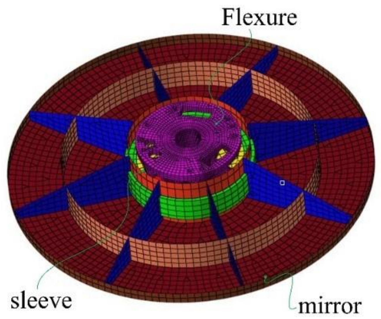
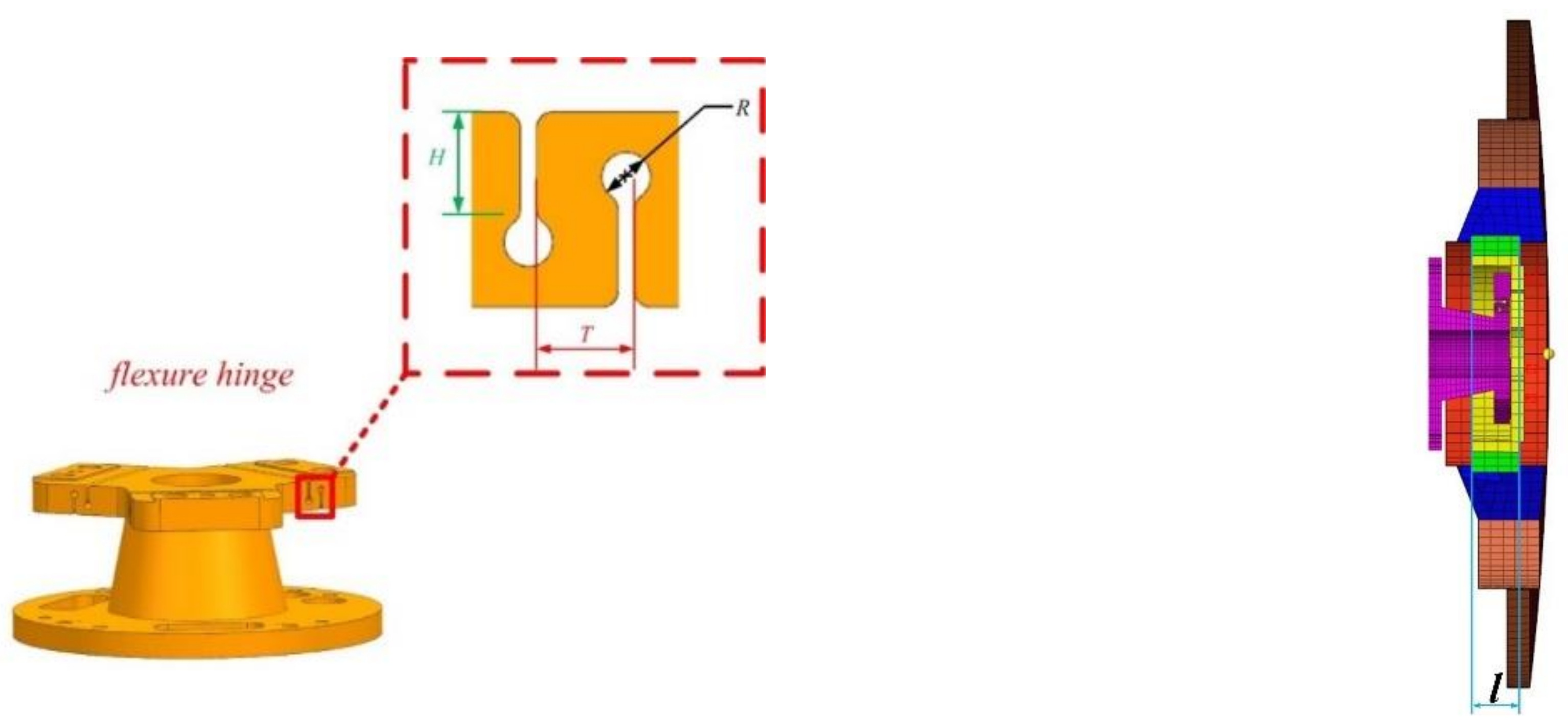
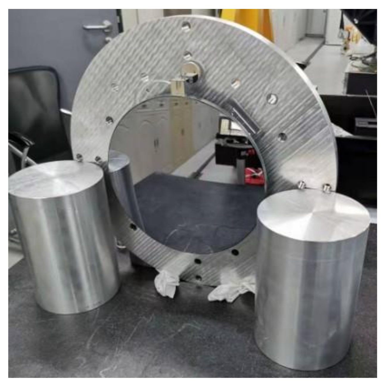
The space mirror assembly is composed of a mirror, a sleeve, and a flexure, and the form of the flexure is shown in Figure 5b. The traditional design method of a mirror assembly is to modify the geometric model through experience, and then apply FEA to optimize it iteratively. The mirror assembly produced by this method depends on the experience of the designer; however, this method is time-consuming. Subsequently, Hu et al. [9] achieved primary mirror assembly optimization by using the connection of UG, Hypermesh, Ansys, Matlab. Their goal was to connect several pieces of software and save the time of manual operation, but the elements of flexure in their model are also a second-order tetrahedron mesh, and the calculation time is also very long. As shown in Figure 6, we establish the Hexahedral FE model by using Hypermesh. The total number of elements is 30,923, and the total number of nodes is 37,815. We alter the parameters of the flexure through the mesh deformation technology by using the Hypermorph module. Three parameters of flexure and axial mount position are shown in Figure 7, namely R, H, T, and l, respectively.
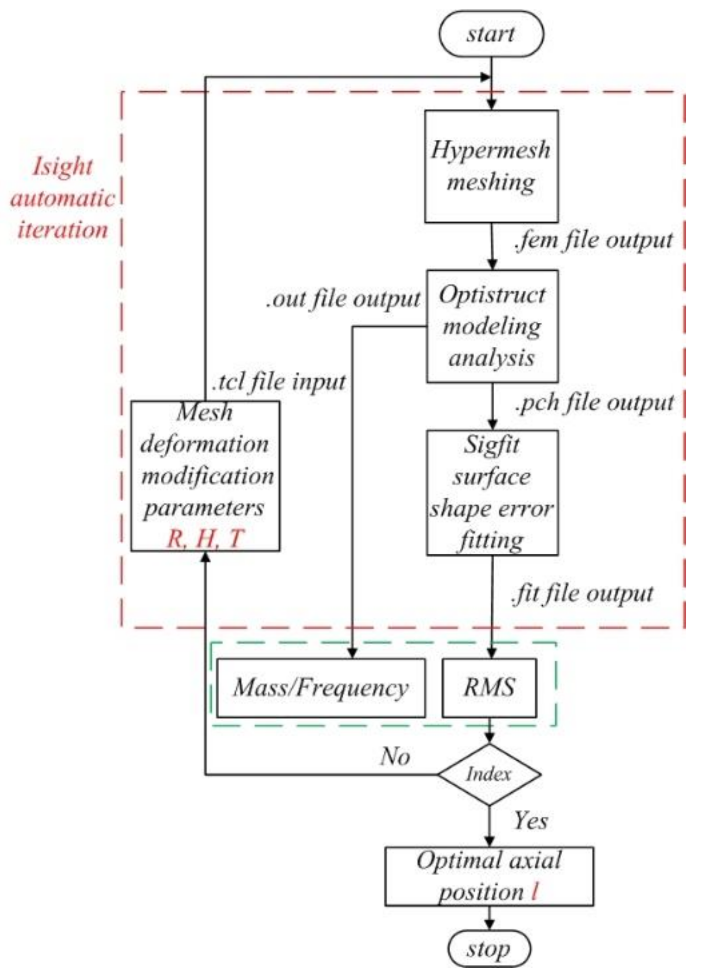
This paper uses Hypermesh for meshing and morph, Optistruct for FEA, and Sigfit to calculate the mirror surface shape error. The automatic optimization design platform for the space mirror is established based on the multidisciplinary optimization software Isight. The computer used in this paper is a Lenovo computer, which has eight CPU cores (i7-6700) and 8 GB of memory. The multi-objective optimization is carried out 1001 times in an optimization routine. The flow of fast optimization of the space mirror assembly is represented in Figure 8. In Figure 8, the flexure size parameters are changed in the tcl script, the tcl script submitted to Hypermesh can generate a fem file, Optistruct calculates a fem file and outputs the mirror surface node deformation, fundamental frequency (f1) and mass, and then Sigfit calculates the RMS. After multiple optimizations, it can be output to meet the optimization mathematical model. Finally, the flexure axial installation position is optimized, and the optimization process ends. The analysis time for the space mirror assembly FEA model under four load cases using a second-order tetrahedron mesh is 10 min, whereas that of the flexure FEA model using the fast optimization method is 40 s. This advantage of less analysis time is more obvious, especially when performing multi-objective optimization.
Due to the RMS under axial gravity being basically unaffected, it is not considered in the multi-objective optimization. The mirror assembly is used in space telescopes, and the space environment experiences temperature changes. The telescope takes temperature control measures, but there is still temperature change after temperature control, and so the RMS value caused by temperature change needs to be considered. Surface shape error caused by temperature is very complex. The complex temperature distribution will cause the temperature gradient to affect the surface shape error of the mirror. The aperture of the mirror is small and it is made of SiC material, which has a fast heat conduction speed and thus can reduce the temperature gradient. Our telescope has a special thermal control team for thermal design to ensure that the mirror works at a temperature of 20 ± 0.1 °C through various means, such as a temperature sensor, a heating plate and thermal coating. Even so, there is still a temperature gradient. We use a large 4 °C uniform temperature change to evaluate the temperature adaptability of the mirror.
According to Equation (5), the multi-objective multi-island genetic algorithm (MIGA) is adopted to optimize the space mirror assembly. RMSt, RMSy, and RMS0.01 represent the RMS value of the mirror surface shape error under 4 °C temperature change, lateral gravity, and 0.01 mm assembly error, respectively. A 0.01 mm assembly error indicates 0.01 mm of non-flatness on the flexible mounting surface. The radius of the flexure mounting surface is 37 mm, and non-flatness can reach 5 microns during traditional grinding, thus a certain margin is required, and we take 0.01 mm for the purposes of simulation. OPI is an optical performance index which represents the weighted value of the surface error under three working conditions. OPI and f1 are the objectives, while the RMS in three loads and mass are the constraints.
The value range, initial value, optimal value, and design value of the space mirror flexure parameters are presented in Table 3. The RMSy of the initial design cannot meet the requirement (5 nm). According to the design values in Table 3, a FEA is conducted by adjusting the axial position of the flexure, and the final results are provided in 
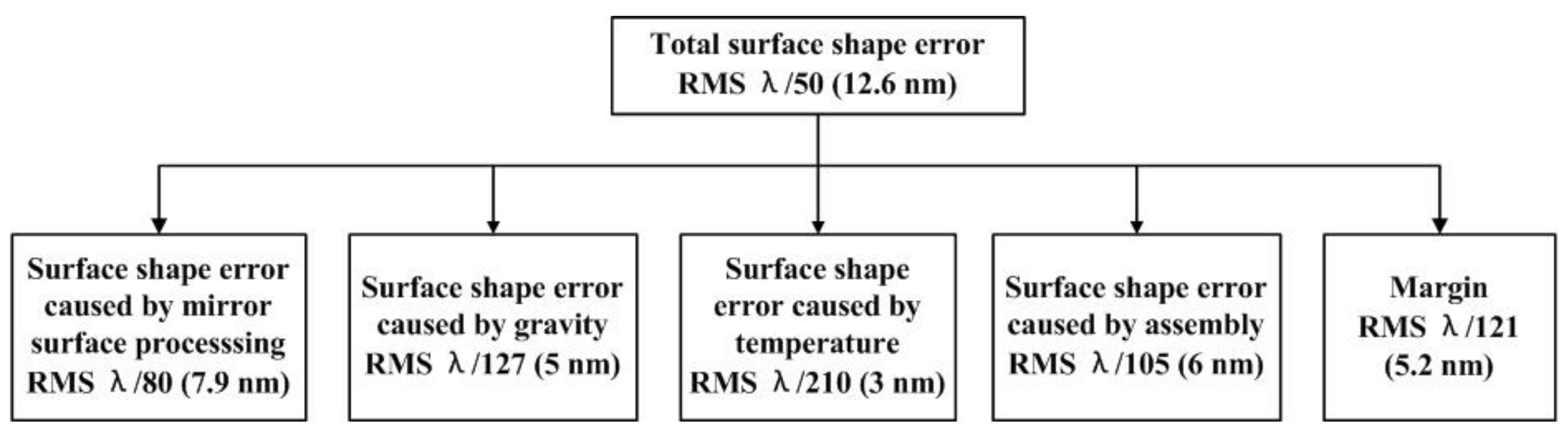
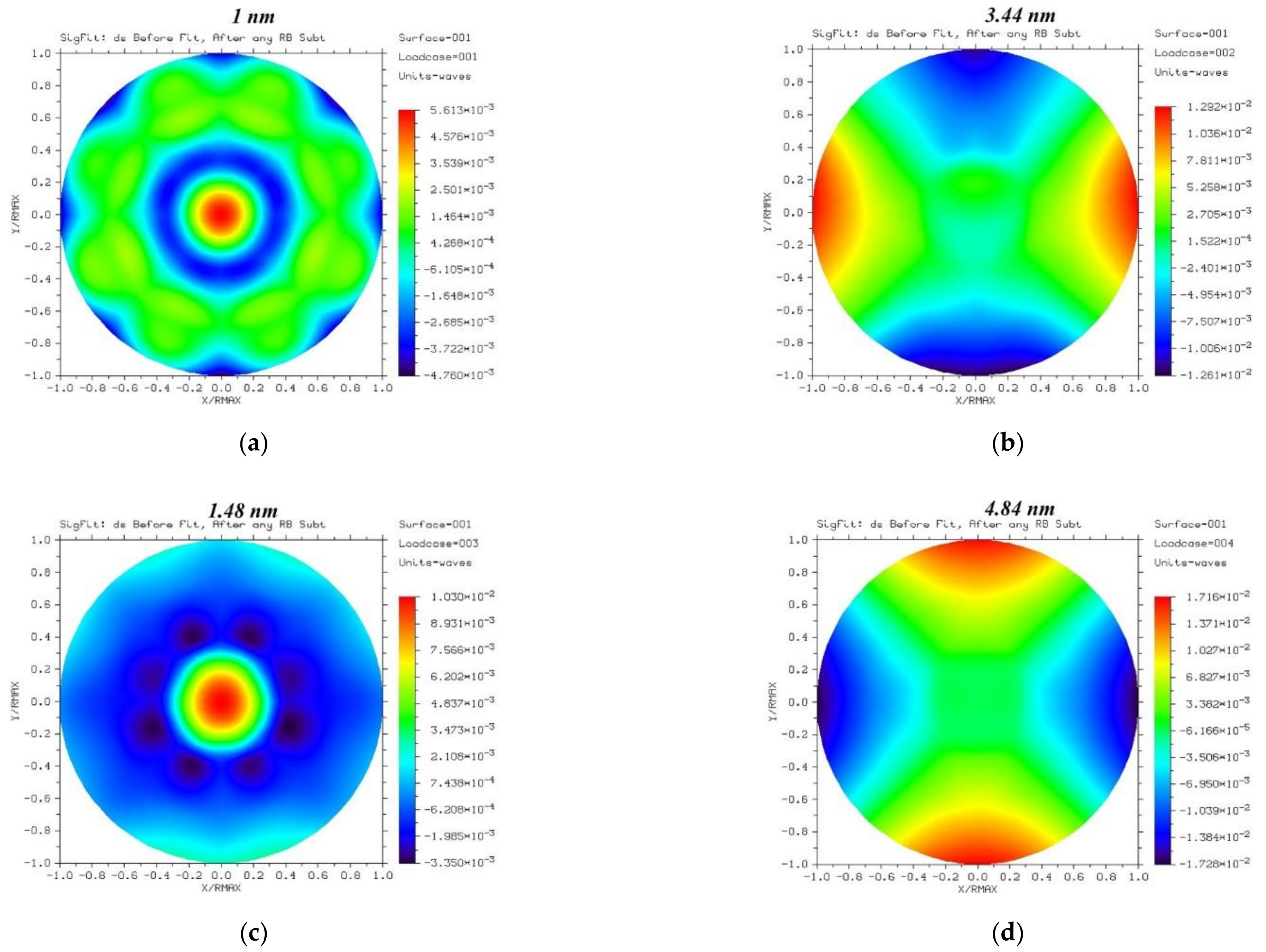
Table 4. The RMS values under lateral gravity, axial gravity, a 4 °C temperature change and a 0.01 mm assembly error are 3.44, 1, 1.48, and 4.84 nm, respectively, and these values satisfy the requirements in Figure 1. The tilt value under lateral gravity of the mirror has a value of 2.63″, which is better than the optimization constraint of 5″. The fundamental frequency of the mirror is 274.4 Hz, which is higher than the design requirement of 120 Hz. The mass of the space mirror assembly is 1.8 kg, which is lower than 2 kg. Compared with the initial design, the OPI reduces by 32.9%, and the fundamental frequency increases by 24.7%. The results show that the multi-objective optimization effect is obvious.
min O P I = ω 1 R M S y + ω 2 R M S t + ω 3 R M S 0.01 max f 1 s . t . f 1 f m M R M S t δ 1 R M S y δ 2 R M S 0.01 δ 3
Here, OPI, which is the weighted mirror surface shape error; the RMSy cannot meet the index requirement, the RMS with a 0.01 mm assembly error can be reduced by grinding, and so the corresponding weight factors were set to ω 1 = 0.5 , ω 2 = 0.3 , ω 3 = 0.2 , respectively. f1 represents the fundamental frequency, m denotes the mass of the space mirror assembly, and RMSt, RMSy, and RMS0.01 represent the optimization constraints of mirror surface shape error in three loads, respectively.
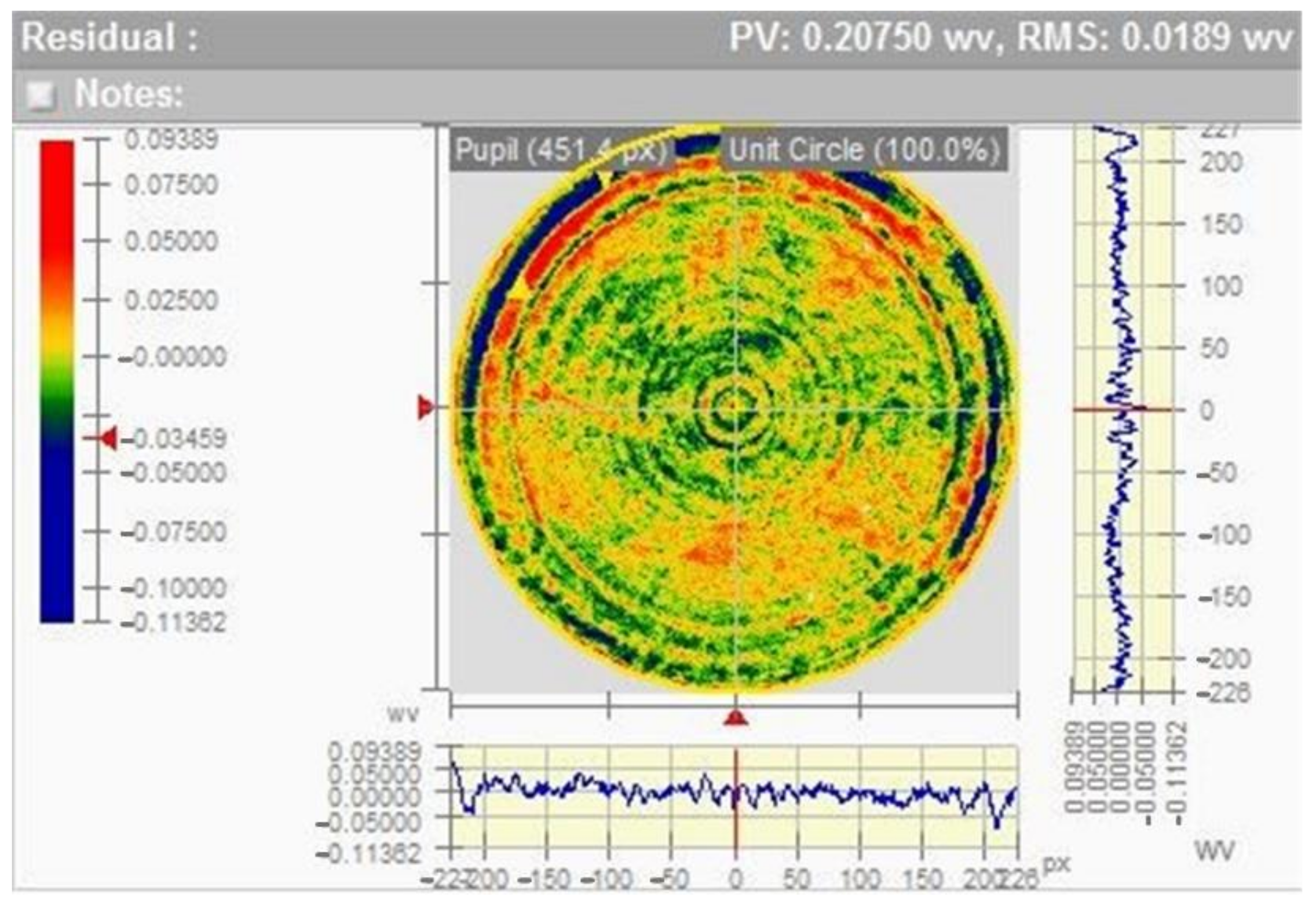
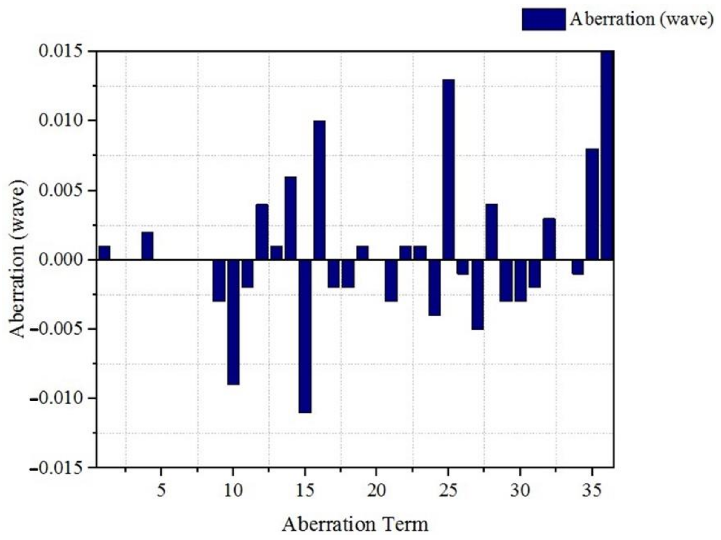
The final result obtained from the space mirror assembly is shown in Figure 9. As shown in Figure 9, the optimization results satisfy the designed error allocation. The total surface shape error RMS meets λ/50. As shown in Figure 9a,c, the remaining primary spherical aberration is the main surface shape error. As shown in Figure 9b,d, the remaining primary astigmatism is the main surface shape error. The astigmatism cannot be removed, while most of the spherical aberration can be removed during installation and adjustment when detecting system wave aberration.

4. Experimental Verification

The mirror is manufactured by reaction sintering, and its processing method is divided into three processes: CNC milling machine processing, small grinding head polishing and magnetorheological processing. When the mirror surface shape error was larger than λ/15 (λ = 632.8 nm), a single mirror surface was processed. When the mirror surface error was processed to λ/15, the invar sleeve was glued to the mirror, and the flexure was screwed to the invar sleeve. At this time, we used high and low temperature and vibration tests to release its assembly stress, and then the mirror was processed in the form of the space mirror assembly. When the surface shape error of the space mirror assembly was processed to λ/50, all environmental experiments were carried out. The coating did not change the mirror surface shape error and other performance parameters. The experimental verification tests were performed as follows.

4.1. Optical Test

Figure 10 shows the optical path of testing the space mirror assembly surface shape error. First, the Zygo interferometer, attenuator, compensator, and space mirror assembly were put on the vibration isolation platform. In the optical path, the attenuator reduces the light intensity, and the compensator is a lens used to detect the aspheric mirror. Compared with the Hindle ball, the advantage of the compensator is that it is small in size, shortens the optical path, and saves the cost. The mirror surface shape error was tested by the Zygo interferometer under coupling load, which included gravity vertical to the optical axis, a 4 °C temperature change, and a non-flatness error of 0.01 mm. The mirror surface shape error was 0.0189λ (<λ/50), which meets the total surface shape error requirement. After the mechanical vibration test, the mirror surface shape error had not changed, the interferogram of space mirror assembly is shown in Figure 11. Low-order spherical aberration, coma, and astigmatism are basically absent. The main surface shape errors are caused by middle and high-order aberrations. The Zernike coefficients are shown in Figure 12. The main error sources are vibration and airflow disturbance. The Zygo interferometer, attenuator, compensator, and space mirror assembly were put on the vibration isolation platform to reduce the influence of vibration. After 12 h of standing still, the test was carried out without staff walking past to reduce the influence of airflow disturbance.

4.2. The Stability Test of the Space Mirror Assembly

According to the improvement and analysis in Section 2.4, by improving the configuration of the flexure, the inclination angle changed from 6.02″ to 2.62″, and the inclination angle of the final space mirror assembly after fast optimization was 2.63″. In order to verify the performance of the improved flexure and the accuracy of the FEA, the stability of the mirror was tested. As shown in Figure 13, the Leica theodolite to measure the inclination angle was 3″, which is better than the design index value. The main error sources are instrument error and operator’s reading error. The instrument accuracy of the Leica theodolite is 1”. The results were verified by multiple measurements by multiple people.

4.3. Mechanical Test

The mechanical vibration test was carried out on the space mirror assembly, and the dynamic characteristics of the space mirror assembly were measured. The testing of the mechanical vibration is shown in Figure 14. The sine vibration and random vibration tests in the X, Y, and Z directions were carried out on the space mirror assembly. The mechanical vibration results showed that the fundamental frequency of the mirror assembly was 270 Hz, which is basically consistent with the FEA simulation, which can verify the accuracy of the FEA simulation.

4.4. The Wave Aberration of the Telescope

At present, the space telescope is in the stage of an integrated assembly. The assembly test site is shown in Figure 15a. The system field of view is 2 ω = 1 5 , and the working spectrum is 280–680 nm. Within the effective field of view, the average RMS of the full field of view is required to be less than λ/14. Due to the small field of view, five characteristic field of view points were used to evaluate the imaging quality of the system image plane. Figure 15b presents the test result of the central field of view, and the other four feature points are (0′, −7′), (0′, +7′), (+7′, 0′), and (−7′, 0′), for which the wave aberrations are 0.0694λ, 0.0701λ, 0.07λ, and 0.0692λ. The average system wave aberration in the whole field of view is 0.06974λ, which is less than λ/14. In the (0′, 0′) field of view, the system wave aberration is 0.07λ, and with astigmatism, coma, and spherical aberration removed, the wave aberration is 0.0628λ, indicating that the proportion of low-order aberrations is very small. The small effect of low-order aberration indicates that the assembly error is basically eliminated, and the main cause of wave aberration is the surface shape error of each mirror. The main error sources are vibration and airflow disturbance. The test system was put on the vibration isolation platform to reduce the influence of vibration. A test shed was built for the test system, and we performed the test without staff walking past after standing still for 12 h to reduce the influence of airflow disturbances.

5. Discussion

A fast optimization method of flexure based on mesh deformation is proposed in this paper, which can improve optimization efficiency compared with other design methods.
In this research, the mesh deformation is completed by adjusting the handle and domain, reduced the time required to change the model and remesh. Compared with the traditional method of calculating the finite element model to obtain the parameters of the flexure [19] and establishing an optimization link to optimize the parametric model of the flexure [11,12], the fast optimization based on mesh deformation in this paper improves the optimization efficiency and saves the optimization time. The larger the diameter of the mirror, the more effective the fast optimization method based on mesh deformation is. Mesh deformation is more suitable for regular size and shape, as complex parameters are difficult to change.
A new frame-type support structure was proposed by Wang [20], and compared with the rectangular mirror supported by a frame the size of the mirror assembly in this paper is small and the support structure is simple. Compared with the back three-point support mirror [21], it has the advantages of a simple structure, being lightweight, and being able to avoid surface shape errors caused by non-flatness. The mirror assembly in this paper and those presented by previous scholars meet the requirements of force-thermal stability and application.

6. Conclusions

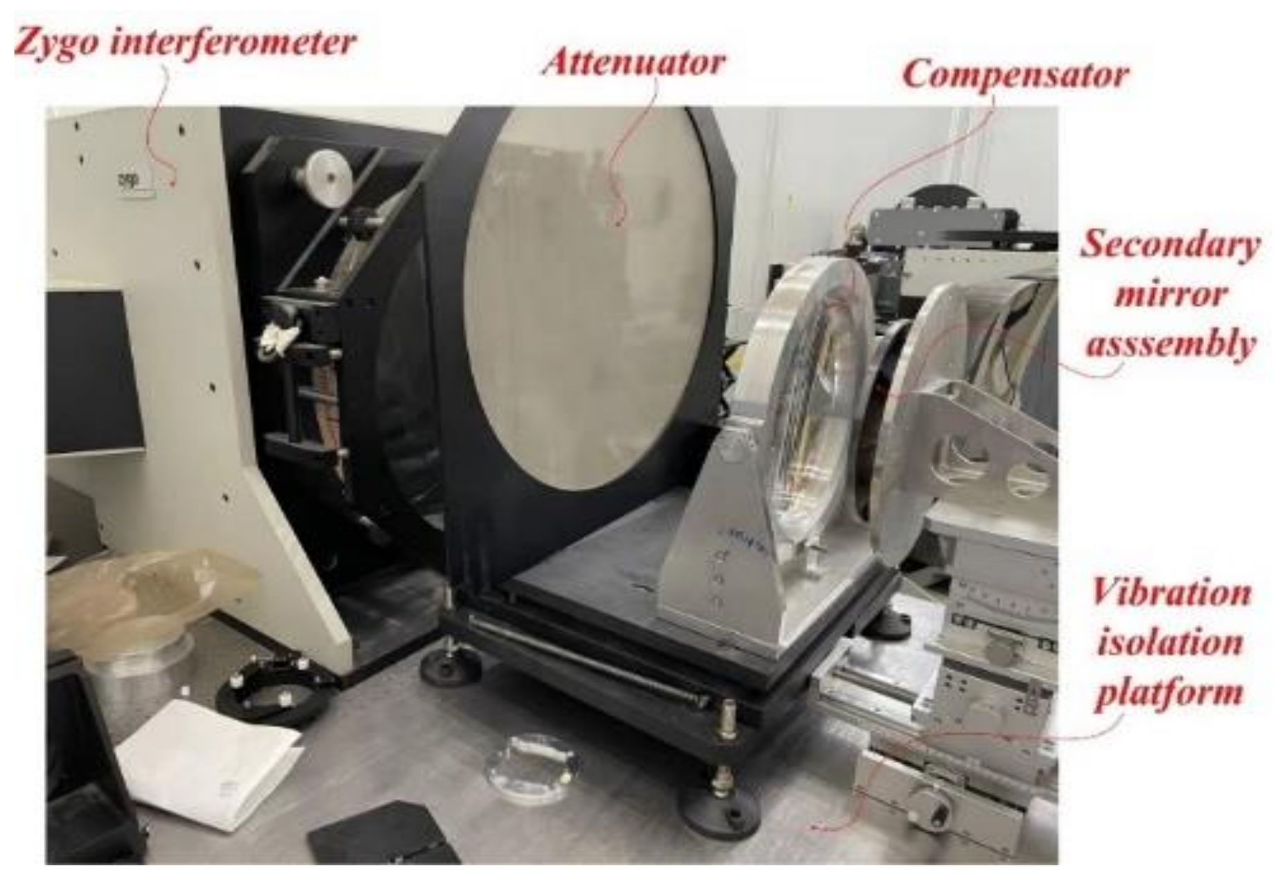
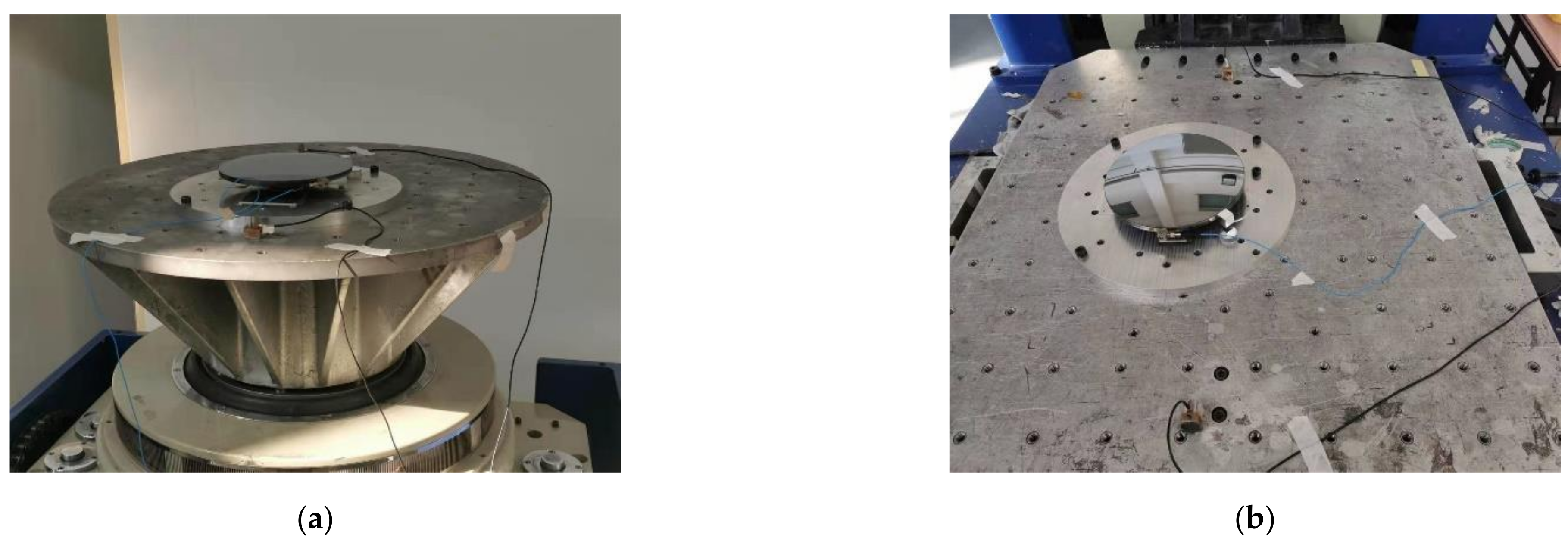
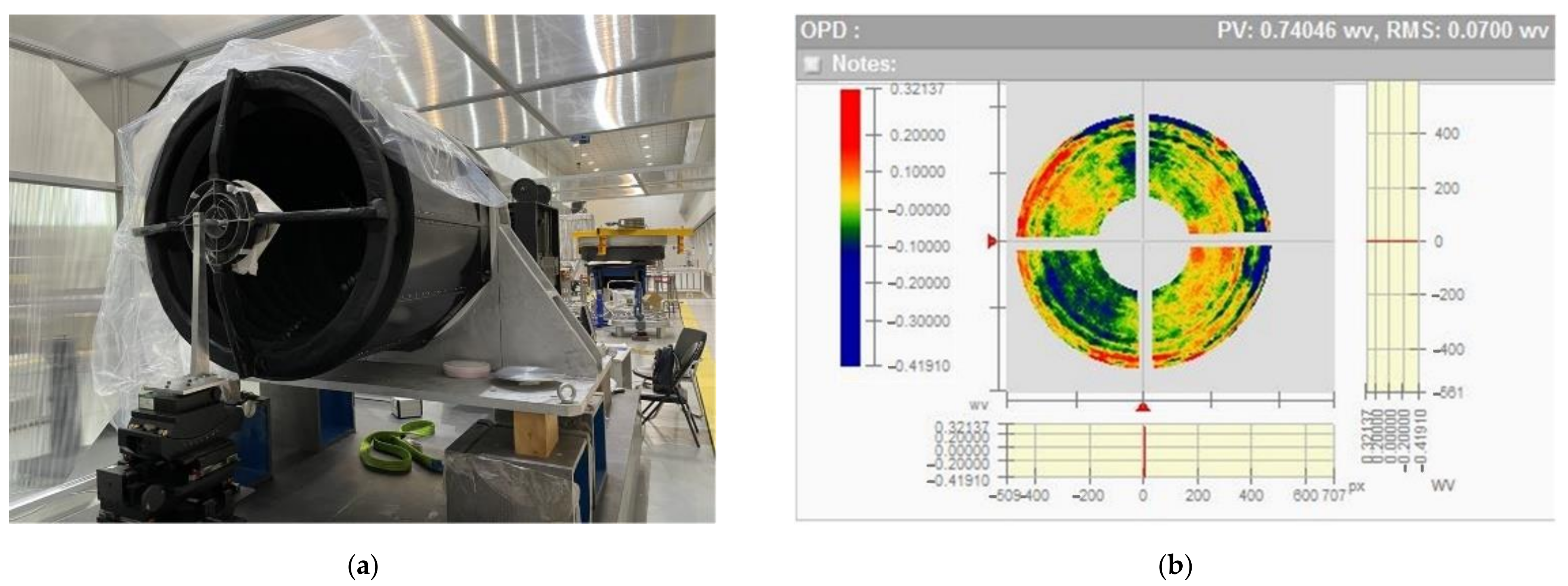
In this paper, the fast optimization method was carried out to improve optimization efficiency. The mirror is created using topology optimization and size optimization; moreover, the flexure with a flexible groove is designed. The flexible groove can release the rotational and translational degrees of freedom, which can minimize the effects of temperature change and assembly tolerance. The size parameters and axial mount position of the flexure were obtained by means of optimization using mesh deformation. This method can significantly improve optimization efficiency. The optimization results of the multi-objective show that the RMS under lateral gravity, axial gravity, 4 °C temperature change and 0.01 mm assembly error are 3.44, 1, 1.48, and 4.84 nm. Moreover, the inclination angle under lateral gravity is 2.63″, and the fundamental frequency is 274.4 Hz, which demonstrates that all indexes satisfy the design requirement. The space mirror assembly is fabricated and assembled for a mechanical test, optical test and stability test. In these tests, the fundamental frequency is 270 Hz, the mirror surface accuracy RMS is λ/50, and the inclination angle under lateral gravity is 3″, and the error of the FEA and tests satisfies the requirements of engineering. The wave aberration of the telescope system is less than λ/14, which satisfies the imaging quality requirements of the optical system. This research provides a meaningful method for improving the optimization efficiency of space mirror assemblies.

Author Contributions

Conceptualization, F.L. and W.L.; Methodology, F.L. and X.W. (Xiaoyu Wang); Validation, F.L., W.L. and X.W. (Xiaoyu Wang); Resources, X.W. (Xiaoyu Wang) and W.L.; Project administration, W.Z. and X.W. (Xiaodong Wang); Funding acquisition, X.W. (Xiaodong Wang); Experiments, F.L., W.L., W.Z. and X.W. (Xiaoyu Wang); Writing—original draft preparation, F.L.; Writing—review and editing, X.W. (Xiaoyu Wang) and W.L. All authors have read and agreed to the published version of the manuscript.

Funding

This research was funded by the Strategic Priority Research Program of Chinese Academy of Sciences, grant number XDA17010205.

Institutional Review Board Statement

Not applicable.

Informed Consent Statement

Not applicable.

Data Availability Statement

The data presented in this study are available on request from the corresponding author.

Conflicts of Interest

The authors declare no conflict of interest.

References

  1. Walker, C.; Kulesa, C.; Bernasconi, P.; Eaton, H.; Rolander, N.; Groppi, C.; Kloosterman, J.; Cottam, T.; Lesser, D.; Wolfire, M.; et al. The Stratospheric THz Observatory (STO). Proc. SPIE Int. Soc. Opt. Eng. 2010, 7733, 77330. [Google Scholar] [CrossRef] [Green Version]
  2. Pascale, E.; Ade, P.A.R.; Bock, J.J.; Chapin, E.L.; Chung, J.; Devlin, M.J.; Dicker, S.; Griffin, M.; Gundersen, J.O.; Halpern, M.; et al. The Balloon-borne Large Aperture Submillimeter Telescope: BLAST. Astrophys. J. 2008, 681, 400–414. [Google Scholar] [CrossRef] [Green Version]
  3. Barthol, P.; Gandorfer, A.; Solanki, S.K.; Schüssler, M.; Chares, B.; Curdt, W.; Deutsch, W.; Feller, A.; Germerott, D.; Grauf, B.; et al. The Sunrise Mission. Sol. Phys. 2011, 268, 1–34. [Google Scholar] [CrossRef] [Green Version]
  4. Song, L.; Yang, S.; Chen, Z.; Zhang, X. Study on optimization design and application of beryllium-mirror of space astronomical instruments. In Proceedings of the 3rd International Symposium on Advanced Optical Manufacturing and Testing Technologies: Large Mirrors and Telescopes, Chengdu, China, 8–12 July 2007; Volume 6721, p. 672107. [Google Scholar]
  5. Zhou, P.; Xu, S.; Yan, C.; Zhang, X. Research on neutral surface of lightweight, horizontally supported mirror. Opt. Eng. 2018, 57, 025107. [Google Scholar] [CrossRef]
  6. Liu, S.; Hu, R.; Li, Q.; Zhou, P.; Dong, Z.; Kang, R. Topology optimization-based lightweight primary mirror design of a large-aperture space telescope. Appl. Opt. 2014, 53, 8318–8325. [Google Scholar] [CrossRef] [PubMed]
  7. Liu, G.; Guo, L.; Wang, X.; Wu, Q. Topology and parametric optimization based lightweight design of a space reflective mirror. Opt. Eng. 2018, 57, 075101. [Google Scholar] [CrossRef]
  8. Jiang, P.; Zhou, P. Optimization of a lightweight mirror with reduced sensitivity to the mount location. Appl. Opt. 2020, 59, 3799–3805. [Google Scholar] [CrossRef] [PubMed]
  9. Qu, Y.; Jiang, Y.; Feng, L.; Li, X.; Liu, B.; Wang, W. Lightweight Design of Multi-Objective Topology for a Large-Aperture Space Mirror. Appl. Sci. 2018, 8, 2259. [Google Scholar] [CrossRef] [Green Version]
  10. Liu, B.; Wang, W.; Qu, Y.-J.; Li, X.-P.; Wang, X.; Zhao, H. Design of an adjustable bipod flexure for a large-aperture mirror of a space camera. Appl. Opt. 2018, 57, 4048–4055. [Google Scholar] [CrossRef] [PubMed]
  11. Chen, Y.-C.; Huang, B.-K.; You, Z.-T.; Chan, C.-Y.; Huang, T.-M. Optimization of lightweight structure and supporting bipod flexure for a space mirror. Appl. Opt. 2016, 55, 10382. [Google Scholar] [CrossRef] [PubMed]
  12. Hu, J.; Dong, J.; Zhou, P. Parametric design of flexure supporting for optical space remote sensor primary mirror. Acta Opt. Sin. 2016, 36, 297–304. [Google Scholar]
  13. Wang, K.; Dong, J.; Zhao, Y.; Chi, C.; Jiang, P.; Wang, X. Research on high performance support technology of space-based large aperture mirror. Optik 2021, 226, 165929. [Google Scholar] [CrossRef]
  14. Cui, Y.P.; He, X.; Zhang, K. The support design of reflected mirror from the principle of three points supported. Opt. Instrum. 2016, 34, 56–61. [Google Scholar]
  15. Yoder, P.R. Opto-Mechanical Systems Design, 3rd ed.; CRC Press: Boca Raton, FL, USA, 2006; pp. 503–506. [Google Scholar]
  16. Bao, Q.; Sha, W.; Chen, C.; Ren, J. Characteristics of rear support in centre for space SiC mirror. Acta Opt. Sin. 2017, 46, 28–37. [Google Scholar]
  17. Li, Z.; Chen, X.; Wang, S.; Jin, G. Optimal design of a Φ760 mm lightweight SiC mirror and the flexural mount for a space telescope. Rev. Sci. Instrum. 2017, 88, 125107. [Google Scholar] [CrossRef] [PubMed]
  18. Chen, P.; Xin, H.; Zhu, J.; Wang, Y.; Xu, Y.; Chen, C. Structural optimization design of lightweight rectangular reflective mirror. Opto-Electron. Eng. 2020, 47, 101–107. [Google Scholar]
  19. Yu, F.; Xu, S. Flexible support structure based on spring principle for a high precision reflecting mirror. Optik 2020, 207, 164341. [Google Scholar] [CrossRef]
  20. Wang, K.; Dong, J.; Wang, X.; Chi, C. Design of frame-type support structure for space-based rectangular convex mirror tested on the back. Optik 2020, 212, 164673. [Google Scholar]
  21. Liu, X.; Tian, X.; Zhang, W.; Zhang, B.; Cheng, Z.; Fu, L.; Wang, Z. Lightweight design of high volume SiC/Al composite mirror for remote camera. Optik 2019, 188, 64–70. [Google Scholar] [CrossRef]
Figure 1. Surface shape error allocation of the mirror component.
Photonics 08 00567 g001
Figure 2. (a) Initial ground structure of mirror. (b) The result of topology optimization.
Photonics 08 00567 g002
Figure 3. The mirror structure.
Photonics 08 00567 g003
Figure 4. The grouping of lightweight ribs.
Photonics 08 00567 g004
Figure 5. The flexure of the space mirror assembly (a) the initial structure of flexure; (b) the improved flexure.
Photonics 08 00567 g005
Figure 6. The FE model of the space mirror assembly.
Photonics 08 00567 g006
Figure 7. The parameters of the flexure.
Photonics 08 00567 g007
Figure 8. The flow of fast optimization.
Photonics 08 00567 g008
Figure 9. The final result under the four load cases: (a) axial gravity; (b) lateral gravity; (c) 4 °C temperature change; (d) 0.01 mm assembly error.
Photonics 08 00567 g009
Figure 10. Test of the mirror surface shape error.
Photonics 08 00567 g010
Figure 11. The interferogram of Zygo testing.
Photonics 08 00567 g011
Figure 12. Zernike coefficient.
Photonics 08 00567 g012
Figure 13. Stability test.
Photonics 08 00567 g013
Figure 14. The test of mechanical vibration: (a) Z-direction vibration (axial) (b) Y-direction vibration (lateral).
Photonics 08 00567 g014
Figure 15. The test of wave aberration: (a) telescope assembly (b) wave aberration.
Photonics 08 00567 g015
Table 1. Material properties of the space mirror assembly.
ComponentMaterialElastic
Modlus (Gpa)
Poisson
Ratio
Desity (g/cm3)Thermal Expansion
Coefficient (10−6/°C)
MirrorSiC3300.253.052.5
SleeveInvar1410.258.92.5
FlexureTitanium1090.344.448.9
Table 2. Design variable and optimization results.
VariableDomainInitial ValueOptimal Value
t1 (mm)(3, 6)43.6
t2 (mm)(3, 6)45
t3 (mm)(3, 6)44.7
t4 (mm)(3, 8)44.8
t5 (mm)(4, 8)64.8
Mass (kg)-1.2341.347
RMSz (nm)-0.8860.691
Table 3. Optimization results of the design variable.
Design
Variable
Value Range (mm)Initial Value (mm)Optimal Value (mm)Design Value (mm)
H(2.5–3.5)3.53.3463.3
T(3–3.5)33.0383
R(0.5–1)10.5140.5
Table 4. Comparison of results between the initial, optimal and final designs.
OPIRMSt (nm)RMSy (nm)RMSz (nm)RMS0.01 (nm)f1 (Hz)
Initial
design
4.671.297.9811.5220
Optimal design3.891.14.9615.38268.6
Finial
design
3.131.483.4414.84274.4
Publisher’s Note: MDPI stays neutral with regard to jurisdictional claims in published maps and institutional affiliations.

