A Novel Liquid Crystal-Filled, Dual-Core Photonic Crystal Fiber Polarization Beam Splitter Covering the E + S + C + L + U Communication Band

Abstract
:1. Introduction
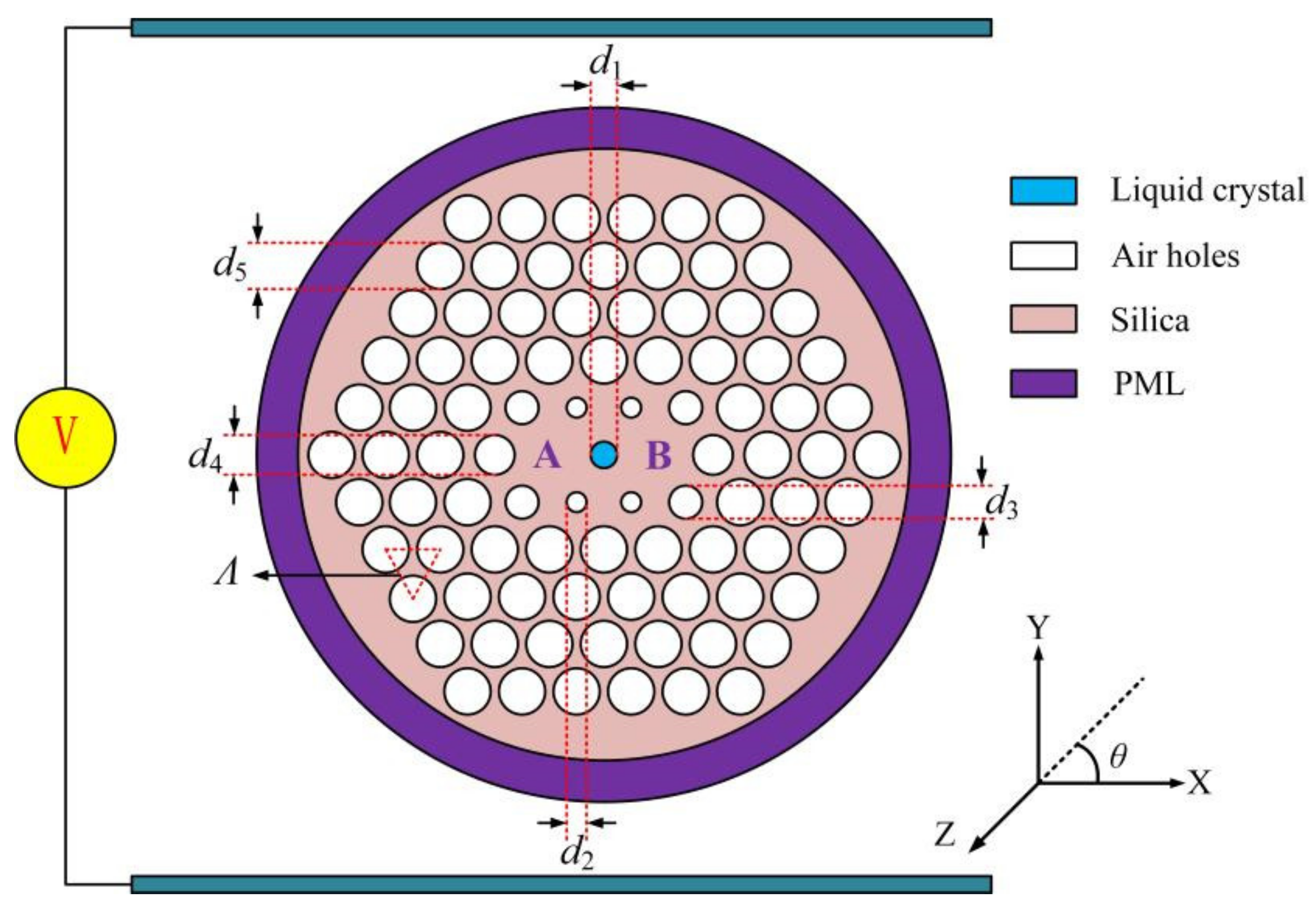
2. Design of the LC-DC-PCF PBS
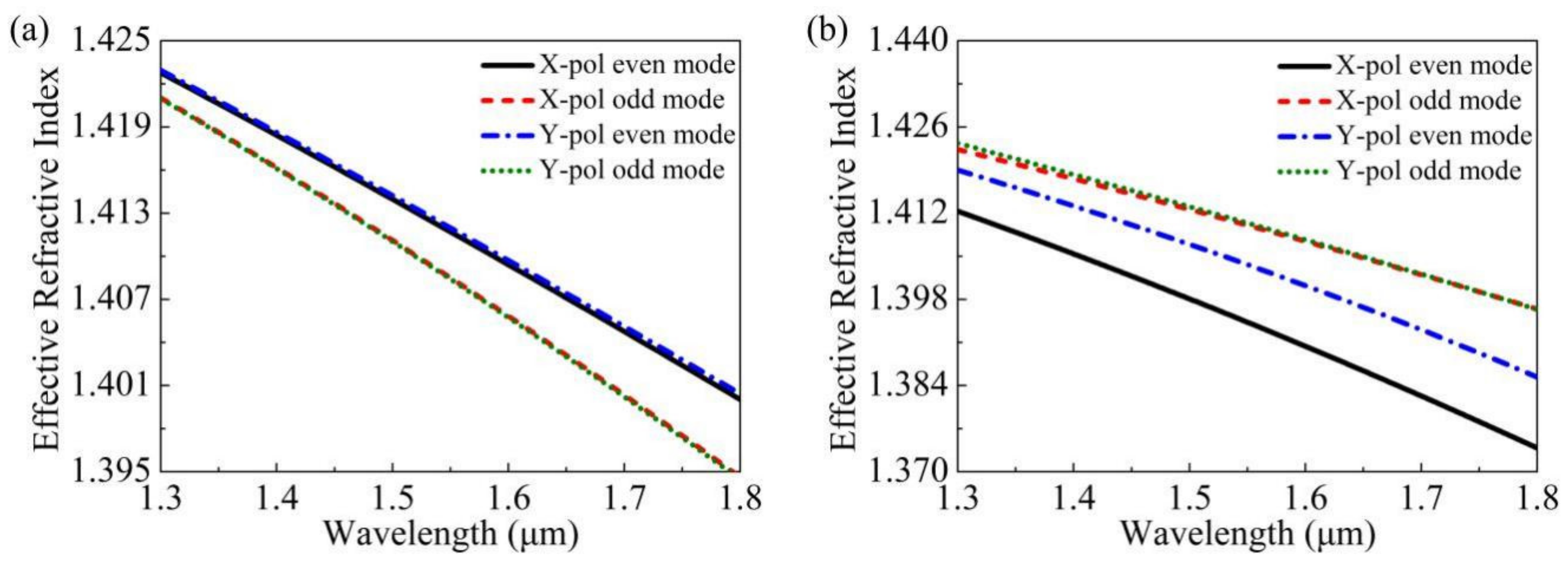
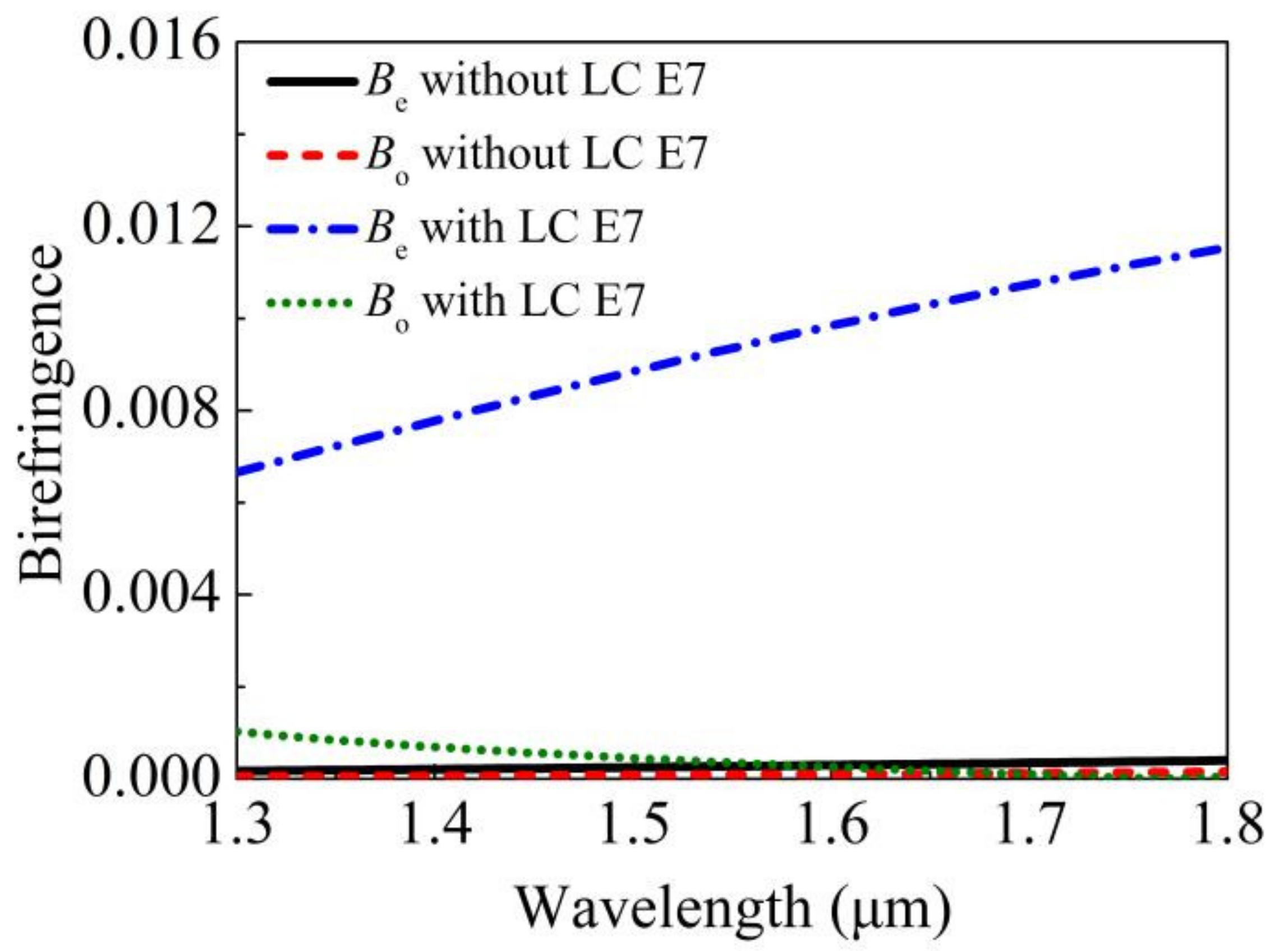
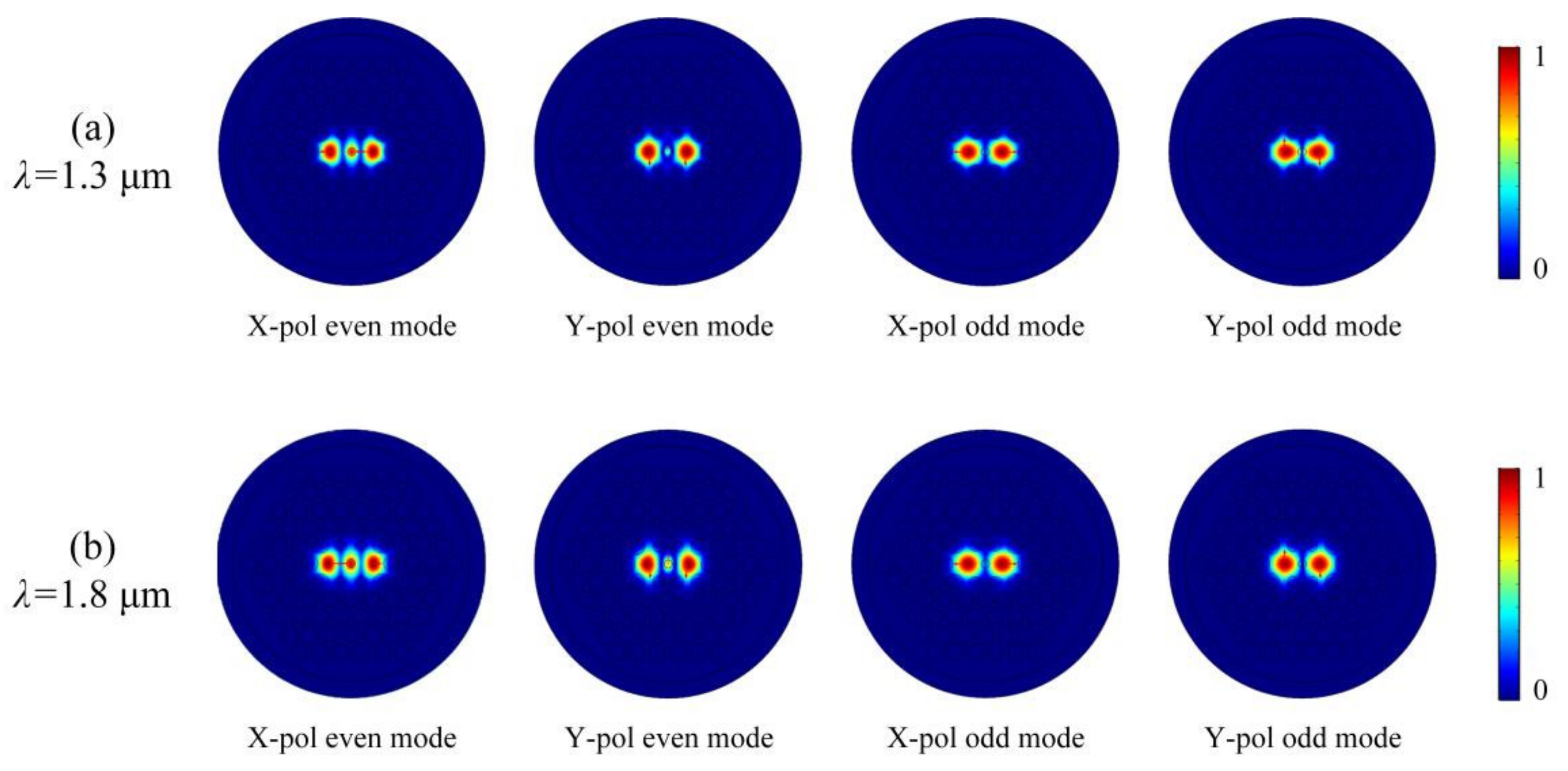
3. Simulation Results
4. Discussion
5. Conclusions
Author Contributions
Funding
Institutional Review Board Statement
Informed Consent Statement
Data Availability Statement
Acknowledgments
Conflicts of Interest
References
- Knight, J.C.; Birks, T.A.; Russell, P.S.J.; Atkin, D.M. All-silica single-mode optical fiber with photonic crystal cladding. Opt. Lett. 1996, 21, 1547–1549. [Google Scholar] [CrossRef]
- Birks, T.A.; Knight, J.C.; Russell, P.S.J. Endlessly single-mode photonic crystal fiber. Opt. Lett. 1997, 22, 961–963. [Google Scholar] [CrossRef]
- Knight, J.C.; Broeng, J.; Birks, T.A.; Russell, P.S.J. Photonic band gap guidance in optical fibers. Science 1998, 282, 1476–1478. [Google Scholar] [CrossRef]
- Islam, R.; Habib, M.S.; Hasanuzzaman, G.K.M.; Ahmad, R.; Rana, S.; Kaijage, S.F. Extremely high-birefringent asymmetric slotted-core photonic crystal fiber in THz regime. IEEE Photon. Technol. Lett. 2015, 27, 2222–2225. [Google Scholar] [CrossRef]
- Xu, Z.L.; Lim, J.L.; Hu, D.J.J.; Sun, Q.Z.; Wong, R.Y.N.; Li, K.; Jiang, M.; Shum, P.P. Investigation of temperature sensing characteristics in selectively infiltrated photonic crystal fiber. Opt. Express 2016, 24, 1699–1707. [Google Scholar] [CrossRef]
- Hu, D.J.J.; Ho, H.P. Recent advances in plasmonic photonic crystal fibers: Design, fabrication and applications. Adv. Opt. Photonics 2017, 9, 257–314. [Google Scholar] [CrossRef]
- Mollaha, M.S.; Yousufalia, M.; Rifat Bin Asif Faysala, M.; Rabiul Hasanb, M.; Biplob Hossainc, M.; Amiri, I.S. Highly sensitive photonic crystal fiber salinity sensor based on Sagnac interferometer. Results Phys. 2020, 16, 103022. [Google Scholar] [CrossRef]
- Maidi, A.M.; Abas, P.E.; Petra, P.I.; Kaijage, S.; Zou, N.Y.; Begum, F. Theoretical considerations of photonic crystal fiber with all uniform-sized air holes for liquid sensing. Photonics 2021, 8, 249. [Google Scholar] [CrossRef]
- Paul, A.K.; Mollah, M.A.; Hassan, M.Z.; Gomez-Cardona, N.; Reyes-Vera, E. Graphene-coated highly sensitive photonic crystal fiber surface plasmon resonance sensor for aqueous solution: Design and numerical analysis. Photonics 2021, 8, 155. [Google Scholar] [CrossRef]
- Haider, F.; Aoni, R.A.; Ahmed, R.; Chew, W.J.; Mahdiraji, G.A. Plasmonic micro-channel based highly sensitive biosensor in visible to mid-IR. Opt. Laser Technol. 2021, 140, 107020. [Google Scholar] [CrossRef]
- Wang, K.; Qu, Y.W.; Yuan, J.H.; Qiu, S.; Zhou, X.; Yan, B.B.; Wu, Q.; Liu, B.; Wang, K.R.; Sang, X.Z.; et al. Ultra-short polarization beam splitter based on dual-core photonic crystal fiber with surface plasmon resonance effect. Opt. Eng. 2021, 60, 076104. [Google Scholar] [CrossRef]
- Wang, C.L.; Shum, P.P.; Hu, D.J.J.; Chen, Y.C.; Xu, Z.L.; Liu, S.H.; Zhang, Y.N.; Zhu, Y.W.; Zheng, Y.; Li, B.C.; et al. Two-core photonic crystal fiber with selective liquid infiltration in the central air hole for temperature sensing. OSA Contin. 2020, 3, 2264–2276. [Google Scholar] [CrossRef]
- Zhang, Y.X.; Qu, Y.W.; Yuan, J.H.; Wang, H.Y.; Zhou, X.; Huo, J.H.; Yan, B.B.; Wu, Q.; Wang, K.R.; Sang, X.Z.; et al. Polarization beam splitter based on the gold wire-filled dual-core photonic crystal fiber at the communication wavelengths. Fiber Integr. Opt. 2021, 40, 1–14. [Google Scholar] [CrossRef]
- Qiu, S.; Yuan, J.H.; Zhou, X.; Qu, Y.W.; Yan, B.B.; Wu, Q.; Wang, K.R.; Sang, X.Z.; Long, K.P.; Yu, C.X. Highly sensitive temperature sensing based on all-solid cladding dual-core photonic crystal fiber filled with the toluene and ethanol. Opt. Commun. 2020, 477, 126357. [Google Scholar] [CrossRef]
- Qu, Y.W.; Yuan, J.H.; Zhou, X.; Feng, L.; Yan, B.B.; Wu, Q.; Wang, K.R.; Sang, X.Z.; Long, K.P.; Yu, C.X. Surface plasmon resonance-based silicon dual-core photonic crystal fiber polarization beam splitter at the mid-infrared spectral region. J. Opt. Soc. Am. B 2020, 37, 2221–2230. [Google Scholar] [CrossRef]
- Chen, H.L.; Li, S.G.; Fan, Z.K.; An, G.W.; Li, J.S.; Han, Y. A novel polarization splitter based on dual-core photonic crystal fiber with a liquid crystal modulation core. IEEE Photo. J. 2014, 6, 2201109. [Google Scholar] [CrossRef]
- Hameed, M.F.O.; Balat, R.T.; Heikal, A.M.; Abo-Elkhier, M.M.; Abo el Maaty, M.I.; Obayya, S.S.A. Polarization-independent surface plasmon liquid crystal photonic crystal multiplexer-demultiplexer. IEEE Photo. J. 2015, 7, 4801110. [Google Scholar] [CrossRef]
- Zi, J.C.; Li, S.G.; Wang, G.Y.; An, G.W.; Fan, Z.K. Design of ultra-short polarization beam splitter based on liquid-filled photonic crystal fiber. Opt. Quant. Electron. 2016, 48, 233. [Google Scholar] [CrossRef]
- Wang, J.S.; Pei, L.; Weng, S.J.; Wu, L.Y.; Ning, T.G.; Li, J. Ultrashort polarization beam splitter based on liquid-filled dual-core photonic crystal fiber. Appl. Opt. 2018, 57, 3847–3852. [Google Scholar] [CrossRef]
- Wang, H.Y.; Yan, X.; Li, S.G.; Zhang, X.N. Tunable surface plasmon resonance polarization beam splitter based on dual-core photonic crystal fiber with magnetic fluid. Opt. Quant. Electron. 2017, 49, 368. [Google Scholar] [CrossRef]
- Wang, J.S.; Pei, L.; Weng, S.J.; Wu, L.Y.; Huang, L.; Ning, T.G.; Li, J. A tunable polarization beam splitter based on magnetic fluids-filled dual-core photonic crystal fiber. IEEE Photo. J. 2017, 9, 2200410. [Google Scholar] [CrossRef]
- Jiang, L.H.; Zheng, Y.; Hou, L.T.; Zheng, K.; Peng, J.Y.; Zhao, X.T. An ultrabraoadband polarization splitter based on square-lattice dualcore photonic crystal fiber with a gold wire. Opt. Commun. 2015, 351, 50–56. [Google Scholar] [CrossRef]
- Li, P.; Zhao, J.L. Polarization-dependent coupling in gold-filled dual-core photonic crystal fibers. Opt. Express 2013, 21, 5232–5238. [Google Scholar] [CrossRef] [PubMed]
- Wang, E.L.; Jiang, H.M.; Xie, K.; Chen, C.; Hu, Z.J. Polarization splitter based on dual core liquid crystal-filled holey fiber. J. Appl. Phys. 2016, 120, 114501. [Google Scholar] [CrossRef]
- Hagras, E.A.A.; Heikal, A.M.; Hamed, M.F.O.; El-Azab, J.M.; El-Nozahi, A.M.; Obayya, S.S.A. Ultra compact soft glass liquid photonic crystal polarization splitter with As2S3 core. Opt. Quant. Electron. 2017, 49, 55. [Google Scholar] [CrossRef]
- Younis, B.M.; Heikal, A.M.; Hameed, M.F.O.; Obayya, S.S.A. Highly wavelength-selective asymmetric dual-core liquid photonic crystal fiber polarization splitter. J. Opt. Soc. Am. B 2018, 35, 1020–1028. [Google Scholar] [CrossRef]
- Xu, Q.; Luo, W.L.; Li, K.; Copner, N.; Lin, S. Design of polarization splitter via liquid and Ti infiltrated photonic crystal fiber. Crystals 2019, 9, 103. [Google Scholar] [CrossRef] [Green Version]
- Rahman, M.T.; Datto, S.; Sakib, M.N. Highly sensitive circular slotted gold-coatedmicro channel photonic crystal fiber basedplasmonic biosensor. OSA Contin. 2021, 4, 1808–1826. [Google Scholar] [CrossRef]
- Qiu, S.; Yuan, J.H.; Zhou, X.; Feng, L.; Wang, Q.W.; Qu, Y.W.; Yan, B.B.; Wu, Q.; Wang, K.R.; Sang, X.Z.; et al. Hollow-core negative curvature fiber with high birefringence for low refractive index sensing based on surface plasmon resonance effect. Sensors 2020, 20, 6539. [Google Scholar] [CrossRef]
- Hameed, M.F.O.; Heikal, A.M.; Younis, B.M.; Abdelrazzak, M.; Obayya, S.S.A. Ultra-high tunable liquid crystal-plasmonic photonic crystal fiber polarization filter. Opt. Express 2015, 23, 7007–7020. [Google Scholar] [CrossRef]
- Jiang, L.H.; Zheng, Y.; Yang, J.J.; Hou, L.T.; Li, Z.H.; Zhao, X.T. An Ultra-broadband single polarization filter based on plasmonic photonic crystal fiber with a liquid crystal core. Plasmonics 2017, 12, 411–417. [Google Scholar] [CrossRef]
- Bao, Y.J.; Li, S.G.; Zhang, W.; An, G.W.; Fan, Z.K. Designing of a polarization beam splitter for the wavelength of 1310 nm on dual-core photonic crystal fiber with high birefringence and double-zero dispersion. Chin. Phys. B 2014, 23, 104218. [Google Scholar] [CrossRef]
- Snyder, A.W.; Love, J.D. Optical Waveguide Theory; Chapman&Hall: London, UK, 1983; pp. 542–552. [Google Scholar]
- Dou, C.; Jing, X.L.; Li, S.G.; Wu, J.J.; Wang, Q.B. A compact and low-loss polarization splitter based on dual-core photonic crystal fber. Opt. Quant. Electron. 2018, 50, 255. [Google Scholar] [CrossRef]
- Jiang, H.M.; Wang, E.L.; Zhang, J.; Hu, L.; Mao, Q.P.; Li, Q.; Xie, K. Polarization splitter based on dual-core photonic crystal fiber. Opt. Express 2014, 22, 30461–30466. [Google Scholar] [CrossRef]
- Zhang, Y.Z.; Liu, H.; Chen, C.; Bai, B.B.; Tang, S.F. Temperature-controlled and multi-functional splitter based on dual-core photonic crystal fiber. Results Phys. 2020, 19, 103578. [Google Scholar] [CrossRef]
- Chu, L.H.; Liu, M.; Shum, P.; Fu, Y.B. Simultaneous achievement of an ultrashort length and a high extinction ratio polarization splitter based on the dual-core photonic crystal fiber with Ge20Sb15Se65 glass. Appl. Opt. 2019, 58, 7892–7896. [Google Scholar] [CrossRef]
- Wang, X.Y.; Li, S.G.; Liu, Q.; Fan, Z.K.; Wang, G.Y.; Zhao, Y.Y. High-extinction ratio and short-length polarization splitter based on microstructured optical fiber with tellurite glass. Opt. Mater. 2017, 66, 542–546. [Google Scholar] [CrossRef]
- Qu, Y.W.; Yuan, J.H.; Qiu, S.; Zhou, X.; Feng, L.; Yan, B.B.; Wu, Q.; Wang, K.R.; Sang, X.Z.; Long, K.P.; et al. A novel gold film-coated V-shape dual-core photonic crystal fiber polarization beam splitter covering the E + S + C + L + U band. Sensors 2021, 21, 496. [Google Scholar] [CrossRef]
- Sun, B.; Chen, M.Y.; Zhang, Y.K.; Zhou, J. Polarization-dependent coupling characteristics of metal-wire filled dual-core photonic crystal fiber. Opt. Quant. Electron. 2015, 47, 441–451. [Google Scholar] [CrossRef]
- Zou, H.; Xiong, H.; Zhang, Y.S.; Ma, Y.; Zheng, J.J. Ultra-broadband polarization splitter based on graphene layer-filled dual-core photonic crystal fiber. Chin. Phys. B 2017, 26, 124216. [Google Scholar] [CrossRef]
- Zhao, Y.Y.; Li, S.G.; Wang, X.Y.; Wang, G.Y.; Shi, M.; Wu, J.J. Design of a novel multi channel photonic crystal fiber polarization beam splitter. Opt. Commun. 2017, 400, 79–83. [Google Scholar] [CrossRef]
- Li, Y.; Itoh, K.; Watanabe, W.; Yamada, K.; Kuroda, D.; Nishii, J.; Jiang, Y.Y. Three-dimensional hole drilling of silica glass from the rear surface with femtosecond laser pulses. Opt. Lett. 2001, 26, 1912–1914. [Google Scholar] [CrossRef] [PubMed]
- Bertoncini, A.; Liberale, C. 3D printed waveguides based on photonic crystal fiber designs for complex fiber-end photonic devices. Optica 2020, 7, 1487–1494. [Google Scholar] [CrossRef]
- Feng, X.; Mairaj, A.K.; Hewak, D.W.; Monro, T.M. Nonsilica glasses for holey fibers. J. Lightw. Technol. 2005, 23, 2046–2054. [Google Scholar] [CrossRef] [Green Version]
- Huang, Y.J.; Wang, Y.; Zhang, L.F.; Shao, Y.; Zhang, F.; Liao, C.R.; Wang, Y.P. Tunable electro-optical modulator based on a photonic crystal fiber selectively filled with liquid crystal. J. Lightw. Technol. 2019, 37, 1903–1908. [Google Scholar] [CrossRef]
- Lin, J.D.; Chiu, C.Y.; Mo, T.S.; Lee, C.R. All-optical directional control of emission in a photonic liquid crystal fiber laser. J. Lightw. Technol. 2020, 38, 5149–5156. [Google Scholar] [CrossRef]
- Liu, Q.; Xue, P.S.; Wu, Q.; Zhao, C.Y.; Ng, W.P.; Fu, Y.Q.; Binns, R. Electrically sensing characteristics of the sagnac interferometer embedded with a liquid crystal-infiltrated photonic crystal fiber. IEEE Trans. Instrum. Meas. 2021, 70, 9511209. [Google Scholar]
- Tian, S.; Yang, T.Y.; Zhang, J.X.; Xie, K.; Ma, J.J.; Hong, L.; Luo, Y.H.; Hu, Z.J. Multi-band thermal optical switch based on nematic liquid crystal filled photonic crystal fiber. J. Lightw. Technol. 2021, 39, 3297–3302. [Google Scholar] [CrossRef]
- Li, Y.; Wang, L.N.; Chen, Y.Z.; Yi, D.; Teng, F.; Hong, X.M.; Li, X.J.; Geng, Y.F.; Shi, Y.; Luo, D. High-performance fiber sensor via Mach-Zehnder interferometer based on immersing exposed-core microstructure fiber in oriented liquid crystals. Opt. Express 2020, 28, 3576–3586. [Google Scholar] [CrossRef]


| Ref. | Structural Characteristics | Splitting Bandwidth | LS | Max ER |
|---|---|---|---|---|
| [16] | Filling liquid crystal E7 in one air hole | 250 nm | 175 μm | 80.7 dB |
| [24] | Filling liquid crystal E7 in all air holes | 150 nm | 890.5 μm | 45 dB |
| [25] | Filling liquid crystal E7 in six air holes and filling As2S3 in one air hole | 88 nm | 111.2 μm | 55 dB |
| [26] | Filling liquid crystal E7 in six air holes | 3 nm | 5678 μm | <30 dB |
| [27] | Filling liquid (ethanol) in six air holes and filling Ti in two air holes | 32.1 nm | 83.9 μm | 44.05 dB |
| [38] | Filling elliptical gold wire in one air hole | 70 nm | 1079 μm | 174.92 dB |
| [39] | Coating gold film in one air hole | 318 nm | 188 μm | <82dB |
| [40] | Filling silver wire in one air hole | 250 nm | 577.5 μm | 42 dB |
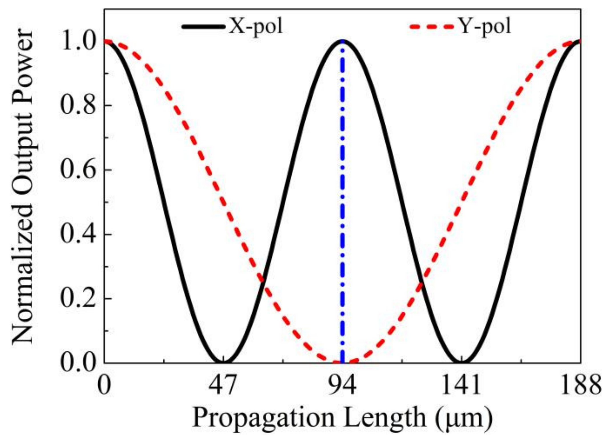
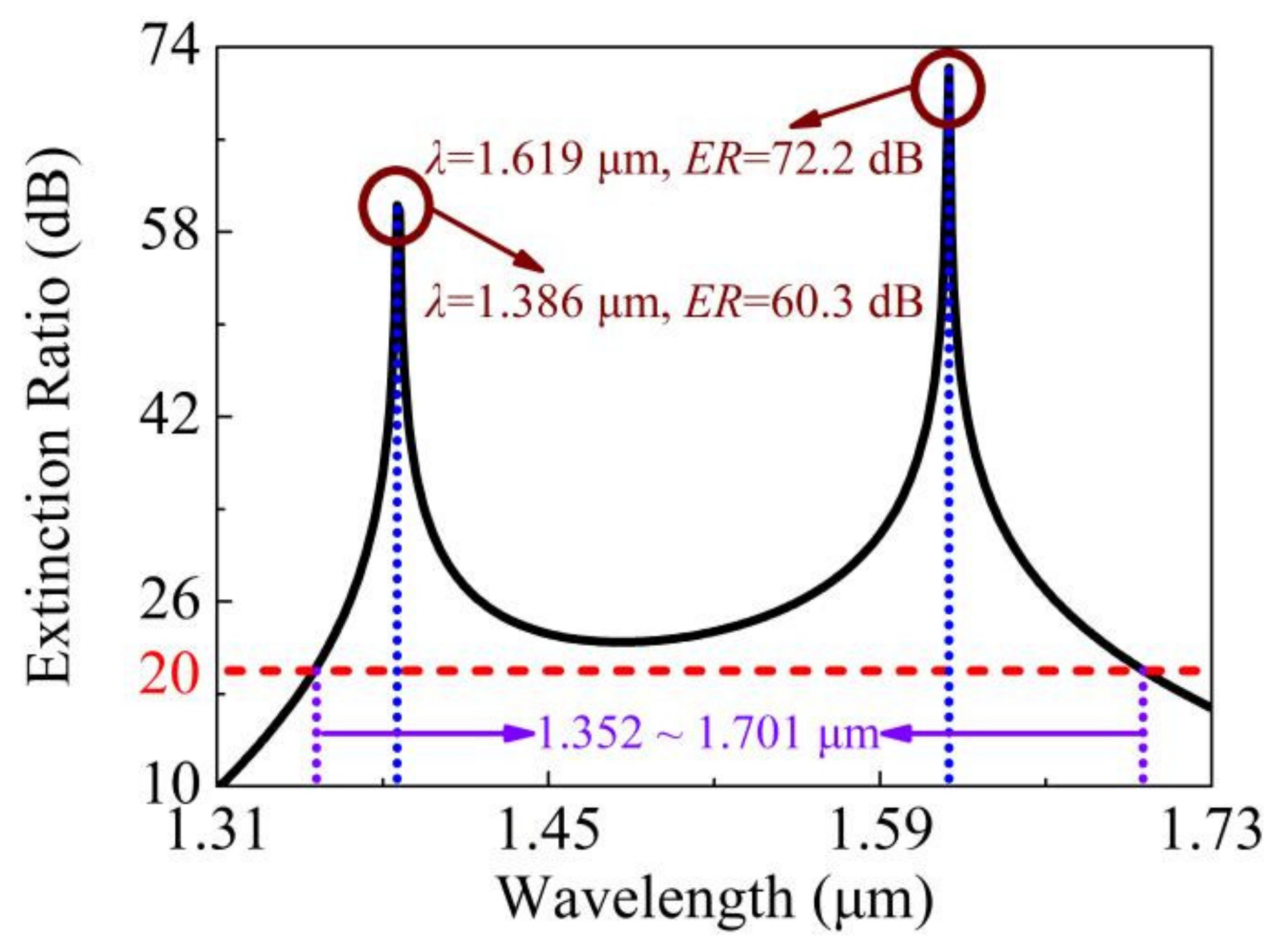
| This work | Filling liquid crystal E7 in one air hole | 349 nm | 94 μm | 72.2 dB |
Publisher’s Note: MDPI stays neutral with regard to jurisdictional claims in published maps and institutional affiliations. |
© 2021 by the authors. Licensee MDPI, Basel, Switzerland. This article is an open access article distributed under the terms and conditions of the Creative Commons Attribution (CC BY) license (https://creativecommons.org/licenses/by/4.0/).
Share and Cite
Qu, Y.; Han, Y.; Yuan, J.; Zhou, X.; Yan, B.; Wang, K.; Sang, X.; Yu, C. A Novel Liquid Crystal-Filled, Dual-Core Photonic Crystal Fiber Polarization Beam Splitter Covering the E + S + C + L + U Communication Band. Photonics 2021, 8, 461. https://doi.org/10.3390/photonics8110461
Qu Y, Han Y, Yuan J, Zhou X, Yan B, Wang K, Sang X, Yu C. A Novel Liquid Crystal-Filled, Dual-Core Photonic Crystal Fiber Polarization Beam Splitter Covering the E + S + C + L + U Communication Band. Photonics. 2021; 8(11):461. https://doi.org/10.3390/photonics8110461
Chicago/Turabian StyleQu, Yuwei, Ying Han, Jinhui Yuan, Xian Zhou, Binbin Yan, Kuiru Wang, Xinzhu Sang, and Chongxiu Yu. 2021. "A Novel Liquid Crystal-Filled, Dual-Core Photonic Crystal Fiber Polarization Beam Splitter Covering the E + S + C + L + U Communication Band" Photonics 8, no. 11: 461. https://doi.org/10.3390/photonics8110461