Double-Frequency-Shift Acousto-Optic Modulator with Controllable Pulse Pair Frequency Difference

 ,
,  ,
, 
 ,
, 
Abstract
:1. Introduction
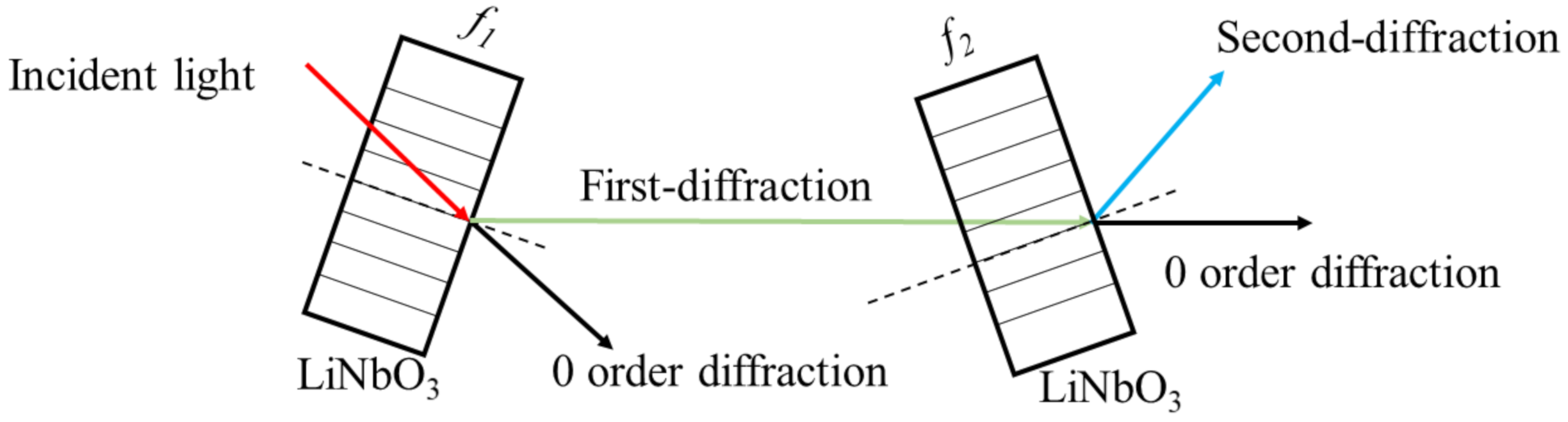
2. System Structure
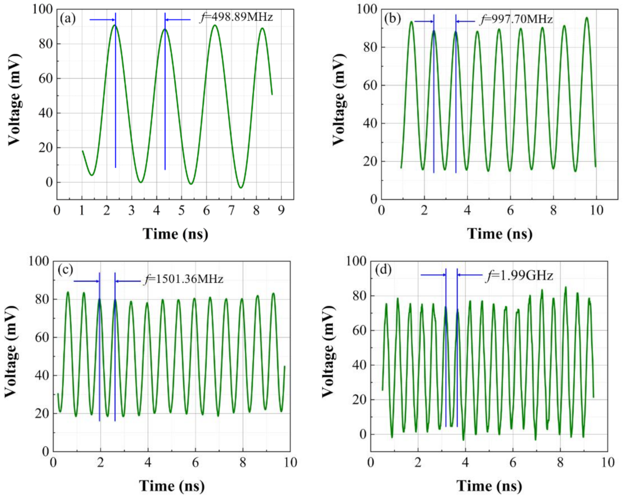
3. Experiment Result
4. Conclusion
Author Contributions
Funding
Institutional Review Board Statement
Informed Consent Statement
Data Availability Statement
Conflicts of Interest
References
- Raman, C.V.; Nagendra Nathe, N.S. The diffraction of light by high frequency sound waves: Part I. Proc. Indian Acad. Sci. 1935, 2, 406–412. [Google Scholar] [CrossRef]
- Kim, B.Y.; Blake, J.N.; Engan, H.E.; Shaw, H.J. All-fiber acousto-optic frequency shifter. Opt. Lett. 1986, 11, 389–391. [Google Scholar] [CrossRef] [PubMed]
- Kakio, S.; Zou, N.; Kitamura, M.; Ito, H.; Nakagawa, Y. An Integrated Acousto-optic Frequency Shifter Driven by Surface Acoustic Wave for 1.55μm Optical Wavelength. Jpn. J. Appl. Phys 2003, 42, 30632003. [Google Scholar] [CrossRef]
- Chou, C.C.; Lu, S.Y.; Lin, T.; Lu, S.H.; Jeng, R.J. Environment-noise-free optical heterodyne retardation measurement using a double-pass acousto-optic frequency shifter. Opt. Lett. 2016, 41, 5138–5141. [Google Scholar] [CrossRef]
- Epikhin, V.M.; Baryshev, V.N.; Slyusarev, S.N.; Aprelev, A.V.; Blinov, I.Y. Acousto-optic modulators for a controlled frequency shift of light beams in optical and microwave cold-atom frequency standards. IEEE J. Quantum Electron. 2019, 49, 857–862. [Google Scholar] [CrossRef]
- Gao, S.L. Sidelobe Problems of Integrated Optical Acousto-Optic Tunable Filter. Chin. J. Lasers 2019, 46, 182–197. [Google Scholar]
- Batshev, V.I.; Machikhin, A.S.; Kozlov, A.B.; Boritko, S.V.; Sharikova, M.O.; Karandin, A.V.; Pozha, V.E.; Lomonov, V.A. Tunable Acousto-Optic Filter for the 450–900 and 900–1700 nm Spectral Range. J. Commun. Technol. El+ 2020, 65, 800–805. [Google Scholar] [CrossRef]
- Zhang, R.Y.; Li, P.L. Acousto-optic tunable flat top filter based on one-dimensional coupled-cavity photonic crystals. Acta Phys. Sin. 2021, 70, 054208. [Google Scholar]
- Mazur, M.M.; Velikovskiy, D.Y.; Mazur, L.I.; Pavluk, A.A.; Pozhar, V.E.; Pustovoit, V.I. Elastic and photo-elastic characteristics of laser crystals potassium rare-earth tungstates KRE(WO4)2, where RE = Y, Yb, Gd and Lu. Ultrasonics 2014, 54, 1311–1317. [Google Scholar] [CrossRef]
- Kastelik, J.C.; Dupont, S.; Yushkov, K.B.; Molchanov, V.Y.; Gazalet, J. Double acousto-optic deflector system for increased scanning range of laser beams. Ultrasonics 2017, 80, 62–65. [Google Scholar] [CrossRef]
- Shinada, H.; Sumi, K.; Shiina, T. Two-dimensional acousto-optic deflector using on-axis anisotropic Bragg diffraction for internal drum scanning exposure systems. Opt. Eng. 2017, 56, 085107. [Google Scholar] [CrossRef]
- Shao, L.B.; Sinclair, N.; Leatham, J.; Hu, Y.W.; Yu, M.J.; Turpin, T.; Crowe, D.; Loncar, M. Integrated microwave acousto-optic frequency shifter on thin-film lithium niobate. Opt. Express 2020, 28, 23728–23738. [Google Scholar] [CrossRef]
- Wu, W.; Tang, S.; Wang, Z.L.; Linghu, A.M.; Zhu, J.; Fu, L.P. Single Polarization Fiber Acousto-Optic Modulator. Piezoelectr. Acoustoopt. 2020, 42, 37–39. [Google Scholar]
- Pillai, G.; Li, S.S. Controllable multichannel acousto-optic modulator and frequency synthesizer enabled by nonlinear MEMS resonator. Sci. Rep. 2021, 11, 10898. [Google Scholar] [CrossRef]
- Yushkov, K.B.; Molchanov, V.Y. Hyperspectral imaging acousto-optic system with spatial filtering for optical phase visualization. J. Biomed. Opt. 2017, 22, 66017. [Google Scholar] [CrossRef]
- He, H.Y.; Sun, J.F.; Hou, P.P.; Zhang, B.; Xu, M.M.; Lao, C.Z. Angle Error Detection of Local Oscillator Nutation Based on Acousto-Optic Deflector in Fine Tracking System. Chin. J. Lasers 2018, 45, 218–224. [Google Scholar]
- Machikhin, A.; Batshev, V.; Pozhar, V.; Naumov, A. Single-volume dual-channel acousto-optical tunable filter. Opt. Express 2020, 28, 1150–1157. [Google Scholar] [CrossRef]
- Yuan, H.; Wang, Y.L.; Lu, Z.W.; Zheng, Z.X. Active frequency matching in stimulated Brillouin amplification for production of a 2.4 J, 200 ps laser pulse. Opt. Lett. 2018, 43, 511–514. [Google Scholar] [CrossRef]
- Liu, D.; Zheng, B.; Guo, H.L.; Liu, H.; Liu, N.Q. Micro-vibration measuring technology based on heterodyne interference. J. Appl. Opt. 2014, 35, 128–131. [Google Scholar]
- Gazalet, M.G.; Ravez, M.; Haine, F.; Bruneel, C.; Bridoux, E. Acousto-optic low-frequency shifter. Appl. Opt. 1994, 33, 1293–1298. [Google Scholar] [CrossRef]
- Kastelik, J.C.; Benaissa, H.; Dupont, S.; Pommeray, M. Acousto-optic tunable filter using double interaction for sidelobe reduction. Appl. Opt. 2009, 48, C4–C10. [Google Scholar] [CrossRef]
- Li, E.B.; Yao, J.Q.; Yu, D.Y.; Xi, J.T.; Chicharo, J. Optical phase shifting with acousto-optic devices. Opt. Lett. 2005, 30, 189–191. [Google Scholar] [CrossRef] [PubMed] [Green Version]
- Dieulangard, A.; Kastelik, J.C.; Dupont, S.; Gazalet, J. Acousto-optic wide band optical low-frequency shifter. Appl. Opt. 2013, 52, 8134–8141. [Google Scholar] [CrossRef] [PubMed]
- Wang, X.X.; Chen, H.Z.; Wu, Z.C.; Wang, Z.L.; Zhou, D.; Liu, G.; Huo, Y.J. A polarization Maintaining Fiber Coupled Acousto-Optical Frequency Shifter Via Double Crystals For Low Frequency Shifting. Piezoelectr. Acoustoopt. 2016, 38, 394–397. [Google Scholar]


Publisher’s Note: MDPI stays neutral with regard to jurisdictional claims in published maps and institutional affiliations. |
© 2021 by the authors. Licensee MDPI, Basel, Switzerland. This article is an open access article distributed under the terms and conditions of the Creative Commons Attribution (CC BY) license (https://creativecommons.org/licenses/by/4.0/).
Share and Cite
Wang, Y.; Lian, Y.; Han, S.; Yu, Y.; Qi, X.; Bai, Z.; Wang, Y.; Lu, Z. Double-Frequency-Shift Acousto-Optic Modulator with Controllable Pulse Pair Frequency Difference. Photonics 2021, 8, 436. https://doi.org/10.3390/photonics8100436
Wang Y, Lian Y, Han S, Yu Y, Qi X, Bai Z, Wang Y, Lu Z. Double-Frequency-Shift Acousto-Optic Modulator with Controllable Pulse Pair Frequency Difference. Photonics. 2021; 8(10):436. https://doi.org/10.3390/photonics8100436
Chicago/Turabian StyleWang, Yuhe, Yudong Lian, Shiwei Han, Yang Yu, Xuan Qi, Zhenxu Bai, Yulei Wang, and Zhiwei Lu. 2021. "Double-Frequency-Shift Acousto-Optic Modulator with Controllable Pulse Pair Frequency Difference" Photonics 8, no. 10: 436. https://doi.org/10.3390/photonics8100436