The Significance of Carrier Leakage for Stable Lasing in Split-Well Direct Phonon Terahertz Quantum Cascade Lasers


Abstract
:1. Introduction
2. Discussion
Funding
Acknowledgments
Conflicts of Interest
References
- Bosco, L.; Franckié, M.; Scalari, G.; Beck, M.; Wacker, A.; Faist, J. Thermoelectrically cooled THz quantum cascade laser operating up to 210 K. Appl. Phys. Lett. 2019, 115, 010601. [Google Scholar] [CrossRef]
- Albo, A.; Hu, Q. Investigating temperature degradation in THz quantum cascade lasers by examination of temperature dependence of output power. Appl. Phys. Lett. 2015, 106, 131108. [Google Scholar] [CrossRef]
- Kumar, S.; Hu, Q.; Reno, J.L. 186 K operation of terahertz quantum-cascade lasers based on a diagonal design. Appl. Phys. Lett. 2009, 94, 131105. [Google Scholar] [CrossRef]
- Albo, A.; Hu, Q. Carrier leakage into the continuum in diagonal GaAs/Al0. 15GaAs terahertz quantum cascade lasers. Appl. Phys. Lett. 2015, 107, 241101. [Google Scholar] [CrossRef]
- Albo, A.; Hu, Q.; Reno, J.L. Room temperature negative differential resistance in terahertz quantum cascade laser structures. Appl. Phys. Lett. 2016, 109, 081102. [Google Scholar] [CrossRef]
- Botez, D.; Kumar, S.; Shin, J.C.; Mawst, L.J.; Vurgaftman, I.; Meyer, J.R. Temperature dependence of the key electro-optical characteristics for midinfrared emitting quantum cascade lasers. Appl. Phys. Lett. 2010, 97, 071101. [Google Scholar] [CrossRef]
- Albo, A.; Flores, Y.V.; Hu, Q.; Reno, J.L. Two-well terahertz quantum cascade lasers with suppressed carrier leakage. Appl. Phys. Lett. 2017, 111, 111107. [Google Scholar] [CrossRef]
- Albo, A.; Flores, Y.V.; Hu, Q.; Reno, J.L. Split-well direct-phonon terahertz quantum cascade lasers. Appl. Phys. Lett. 2016, 114, 191102. [Google Scholar] [CrossRef] [Green Version]
- Winge, D.O.; Dupont, E.; Wacker, A. Ignition of quantum cascade lasers in a state of oscillating electric field domains. Phys. Rev. A 2018, 98, 023834. [Google Scholar] [CrossRef] [Green Version]
- Khabibullin, R.A.; Shchavruk, N.V.; Ponomarev, D.S.; Ushakov, D.V.; Afonenko, A.A.; Maremyanin, K.V.; Volkov, O.Y.; Pavlovskiy, V.V.; Dubinov, A.A. The operation of THz quantum cascade laser in the region of negative differential resistance. Opto-Electron. Rev. 2019, 27, 329. [Google Scholar] [CrossRef]
- Williams, B.S.; Kumar, S.; Qin, Q.; Hu, Q.; Reno, J.L. Terahertz quantum cascade lasers with double-resonant-phonon depopulation. Appl. Phys. Lett. 2006, 88, 261101. [Google Scholar] [CrossRef] [Green Version]
- Kumar, S.; Chan, C.W.I.; Hu, Q.; Reno, J.L. Two-well terahertz quantum-cascade laser with direct intrawell-phonon depopulation. Appl. Phys. Lett. 2009, 95, 141110. [Google Scholar] [CrossRef] [Green Version]
- Scalari, G.; Amanti, M.I.; Walther, C.; Terazzi, R.; Beck, M.; Faist, J. Broadband THz lasing from a photon-phonon quantum cascade structure. Opt. Express 2010, 18, 8043. [Google Scholar] [CrossRef] [PubMed]
- Chan, C.W.I. Towards Room-Temperature Terahertz Quantum Cascade Lasers: Directions and Design. Ph.D. Thesis, Department of Electrical Engineering and Computer Science, Massachusetts Institute of Technology, Cambridge, MA, USA, 2015. [Google Scholar]
- Chan, C.W.I.; Albo, A.; Hu, Q.; Reno, J.L. Tradeoffs between oscillator strength and lifetime in terahertz quantum cascade lasers. Appl. Phys. Lett. 2016, 109, 201104. [Google Scholar] [CrossRef]
- Albo, A.; Flores, Y.V. Temperature-driven enhancement of the stimulated emission rate in terahertz quantum cascade lasers. IEEE J. Quantum Electron. 2017, 53, 2300105. [Google Scholar] [CrossRef]
- Franckié, M.; Bosco, L.; Beck, M.; Bonzon, C.; Mavrona, E.; Scalari, G.; Wacker, A.; Faist, J. Two-well quantum cascade laser optimization by non-equilibrium Green’s function modelling. Appl. Phys. Lett. 2018, 112, 021104. [Google Scholar] [CrossRef] [Green Version]
- Albo, A.; Flores, Y.V. Carrier leakage dynamics in terahertz quantum cascade lasers. IEEE J. Quantum Electron. 2017, 53, 8500508. [Google Scholar] [CrossRef]
- Baranov, A.N.; Van, H.N.; Loghmari, Z.; Bahriz, M.; Teissier, R. Terahertz quantum cascade laser with non-resonant extraction. AIP Adv. 2019, 9, 055214. [Google Scholar] [CrossRef]
- Franckie, M.; Faist, J. Bayesian Optimization of Terahertz Quantum Cascade Lasers. Phys. Rev. Appl. 2020, 13, 034025. [Google Scholar] [CrossRef] [Green Version]
- Vitiello, M.S.; Scamarcio, G.; Spagnolo, V.; Williams, B.S.; Kumar, S.; Hu, Q.; Reno, J.L. Measurement of subband electronic temperatures and population inversion in THz quantum-cascade lasers. Appl. Phys. Lett. 2005, 86, 111115. [Google Scholar] [CrossRef]
- Harrison, P.; Indjin, D.; Kelsall, R.W. Electron temperature and mechanisms of hot carrier generation in quantum cascade lasers. J. Appl. Phys. 2002, 92, 6921–6923. [Google Scholar] [CrossRef] [Green Version]
- Spagnolo, V.; Scamarcio, G.; Page, H.; Sirtori, C. Simultaneous measurement of the electronic and lattice temperatures in GaAs/Al 0.45 Ga 0.55 as quantum-cascade lasers: Influence on the optical performance. Appl. Phys. Lett. 2004, 84, 3690–3692. [Google Scholar] [CrossRef]
- Almqvist, T.; Winge, D.O.; Dupont, E.; Wacker, A. Domain formation and self-sustained oscillations in quantum cascade lasers. Eur. Phys. J. B 2019, 92, 72. [Google Scholar] [CrossRef]
- Flores, Y.V.; Albo, A. Impact of interface roughness scattering on the performance of GaAs/Al x Ga 1–x as terahertz quantum cascade lasers. IEEE J. Quantum Electron. 2017, 53, 1–8. [Google Scholar]
- Greck, P.; Birner, S.; Huber, B.; Vogl, P. Efficient method for the calculation of dissipative quantum transport in quantum cascade lasers. Opt. Express 2015, 23, 6587. [Google Scholar] [CrossRef]


| Device | Lasing Energy [meV] | E21 [meV] | Oscillator Strength | Nom. Expected Activation Energy [meV] | E47 [meV] | Layer Sequence [#ML*], Barrier Composition and Doping Level | Process Details |
|---|---|---|---|---|---|---|---|
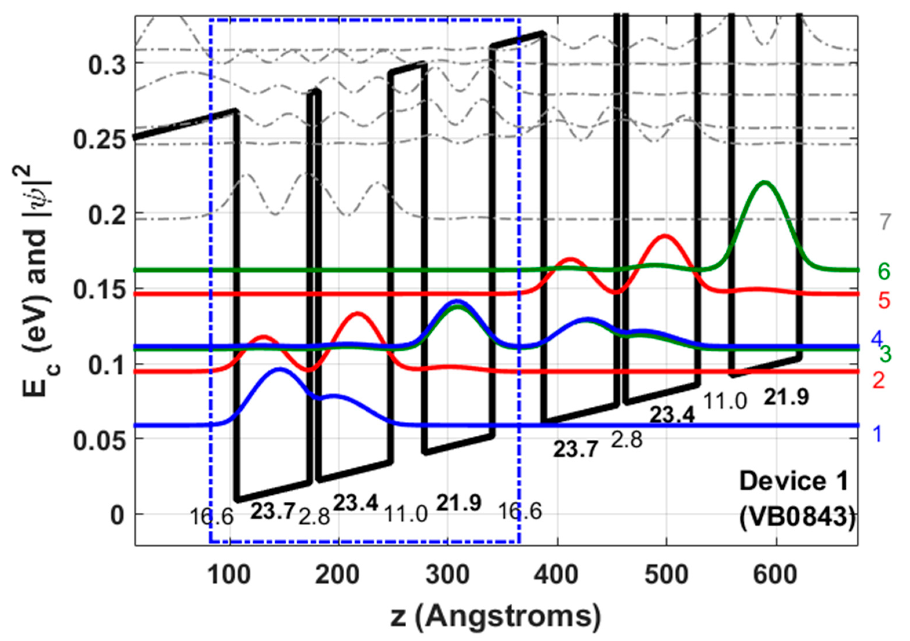
| Device 1 (VB0843), (Figure 1) | 14.9 | 36 | 0.22 | 21.1 | 84.6 | 16.6/23.7/2.8/23.4/11.0/21.9 355 periods GaAs/Al0.30Ga0.70As 2.24 × 1016 cm−3 in the 23.7 and 23.4 ML wells (2.98 × 1010 cm−2). | Metal–metal (100 Å Ta/2500 Å) Top contact n+ layer was removed Dry etched Mesa size 150 μm × 1.8 mm |
| Device 2 (VB0837) ([8]) | 11.1 | 34.5 | 0.26 | 24.9 | 72.5 | 9.0/24.8/3.5/24.8/17.3/24.8 353 periods GaAs/mixed barriers Al0.55Ga0.45As (Injector) and Al0.15Ga0.85As (Radiative, Intrawell) 2.13 × 1016 cm−3 in the 24.8 ML wells (2.98 × 1010 cm−2). | Metal-metal (100 Å Ta/2500 Å Au) Top contact n+ layer was removed Dry etched Mesa size 150 μm × 1.8 mm |
| Device 3 (VB0847) (Figure 5) | 10.7 | 34.5 | 0.25 | 25.3 | 75.1 | 9.0/26.2/3.5/25.8/10.3/26.9 362 periods GaAs/mixed barriers: Al0.55Ga0.45As (Injector), Al0.30Ga0.70As (Radiative) and Al0.15Ga0.85As (Intrawell) 2.03 × 1016 cm−3 in the 26.2 and 25.8 ML wells (2.98 × 1010 cm−2). | Metal-metal (100 Å Ta/2500 Å) Top contact n+ layer was removed Dry etched Mesa size 150 μm × 1.8 mm |
| Device | Injection Coupling
[meV] | Design Electric Field [kV/cm] | τ0ul [ps] * | τ021 [ps] ** | IFR Gain Broadening [meV] *** | Exp. Lasing Energy [meV] | Expected Activation Energy [meV] | Jth (10 K) [A/cm2] | Jmax (10 K)[A/cm2] | Dynamic Range (10 K) [A/cm2] | Jmax (290 K) [A/cm2] | Tmax [K] |
|---|---|---|---|---|---|---|---|---|---|---|---|---|
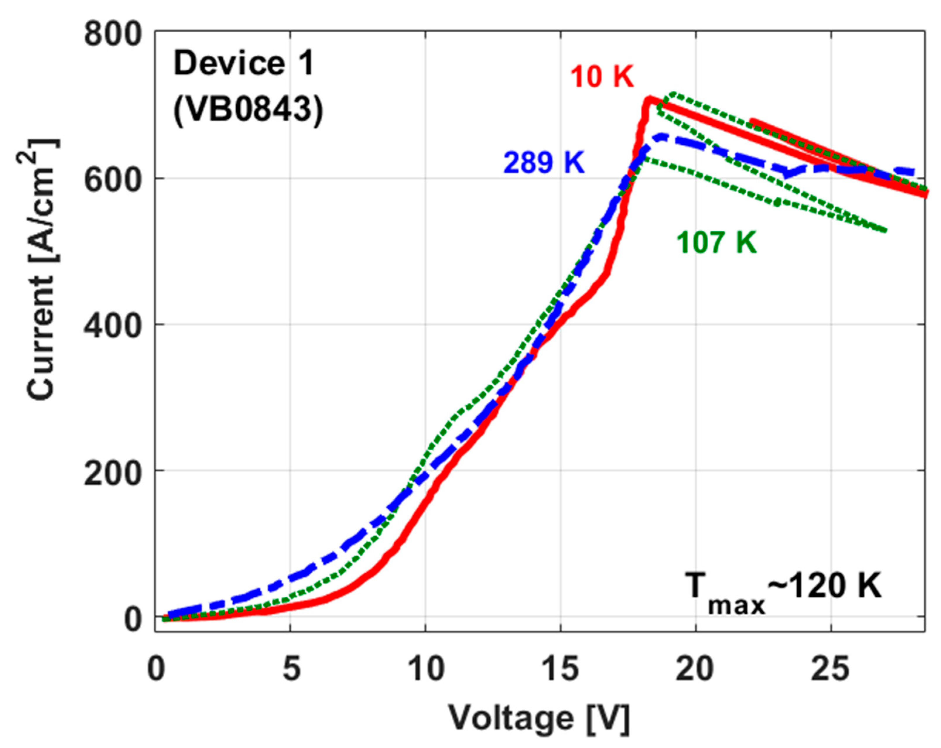
| Device 1 (VB0843), (Figure 1) | 1.87 | 18.4 | 1.23 | 0.17 | 4.19 | 16.6 | 19.4 | 463 | 708 | 245 | 657 | 120 |
| Device 2 (VB0837) ([8]) | 2.08 | 16.5 | 1.21 | 0.18 | 4.37 | 10.05 | 25.5 | 578 | 928 | 350 | 750 | 170 |
| Device 3 (VB0847) (Figure 5) | 2.12 | 16.8 | 1.08 | 0.19 | 4.10 | 10.8 | 25.2 | 578 | 625 | 47 | 646 | 57 |
© 2020 by the authors. Licensee MDPI, Basel, Switzerland. This article is an open access article distributed under the terms and conditions of the Creative Commons Attribution (CC BY) license (http://creativecommons.org/licenses/by/4.0/).
Share and Cite
Lander Gower, N.; Piperno, S.; Albo, A. The Significance of Carrier Leakage for Stable Lasing in Split-Well Direct Phonon Terahertz Quantum Cascade Lasers. Photonics 2020, 7, 59. https://doi.org/10.3390/photonics7030059
Lander Gower N, Piperno S, Albo A. The Significance of Carrier Leakage for Stable Lasing in Split-Well Direct Phonon Terahertz Quantum Cascade Lasers. Photonics. 2020; 7(3):59. https://doi.org/10.3390/photonics7030059
Chicago/Turabian StyleLander Gower, Nathalie, Silvia Piperno, and Asaf Albo. 2020. "The Significance of Carrier Leakage for Stable Lasing in Split-Well Direct Phonon Terahertz Quantum Cascade Lasers" Photonics 7, no. 3: 59. https://doi.org/10.3390/photonics7030059