1. Introduction
In recent decades, distributed Brillouin optical time domain analyzer (BOTDA) has been intensively investigated for a wide variety of applications, including temperature analysis [
1,
2] and structure health monitoring [
3,
4]. It’s capability to provide highly precise and distributed measurements of strain and temperature profiles has been demonstrated [
5,
6]. However, due to the frequency-scanning nature, the acquisition time and post-processing time of most existing BOTDAs can vary from seconds to minutes when sensing ranges and spatial resolutions changes [
7,
8,
9,
10], which limits its development in the field of fast distributed monitoring systems, such as a vibration measuring system for long sensing range and high spatial resolution for civil or aeronautic structures applications [
11,
12].
To solve the problem of long acquisition times, a variety of scanning-free BOTDA (SF-BOTDA) or single-shot methods was proposed [
13,
14,
15,
16,
17,
18]. For example, slope-assisted BOTDA is realized based on tuning the frequency of probe optical signal to half of BGS which can effectively shorten the measurement time [
13]. In Ba et al. [
14], another kind of scanning-free BOTDA is proposed based on multiple probes and pump pairs that allows for the fast measurement of strain or temperature changes along the fiber. Moreover, Jin et al. proposed a digitally generated optical-frequency-comb-based BOTDA to realize scanning-free BOTDA and single measurement BOTDA in 2015 and 2017 respectively, with an acquisition time of 100 μs for a 10 km optical fiber [
15,
16]. In Fang et al. [
17], a dual-polarization probe with orthogonal frequency-division multiplexing (OFDM) modulation is used for a single-shot BOTDA system where frequency scanning and polarization scrambling are no longer required. A single-shot BOTDA based on an optical chirp chain probe wave is also proposed for distributed ultrafast measurements with a sampling rate of up to the MHz level [
18]. These efforts mean that the time consumption of acquisition is no longer the bottleneck of a real-time BOTDA.
Although SF-BOTDA can significantly reduce the time consumption of acquisition, it produces a huge amount of data and requires complicated calculations in the subsequent data processing, such as frame synchronization, fast Fourier transform (FFT), and phase calculation, which has become a new factor restricting the BOTDA system’s real-time application [
15,
16]. During post-processing, synchronization is only required to be implemented once such that the SF-BOTDA system can keep running until the fiber sensing data acquisition is completed. However, such a synchronization process usually takes a few milliseconds, and since the subsequent data processing can only be carried out after the completion of frame synchronization, the time consumed by synchronization will affect the real-time performance of the BOTDA system.
To address issues regarding the high time consumption of the frame synchronization present in the SF-BOTDA system, a novel frame synchronization algorithm was proposed. The proposed algorithm can avoid a lot of redundant calculations for frame synchronization by using the incremental updating method, and therefore reduce the computational complexity. In addition, to further accelerate the real-time performance of frame synchronization, a field programmable gate array (FPGA) hardware implementation architecture based on parallel processing and pipelining mechanisms was also proposed.
2. Basic Principle
2.1. Frame Synchronization
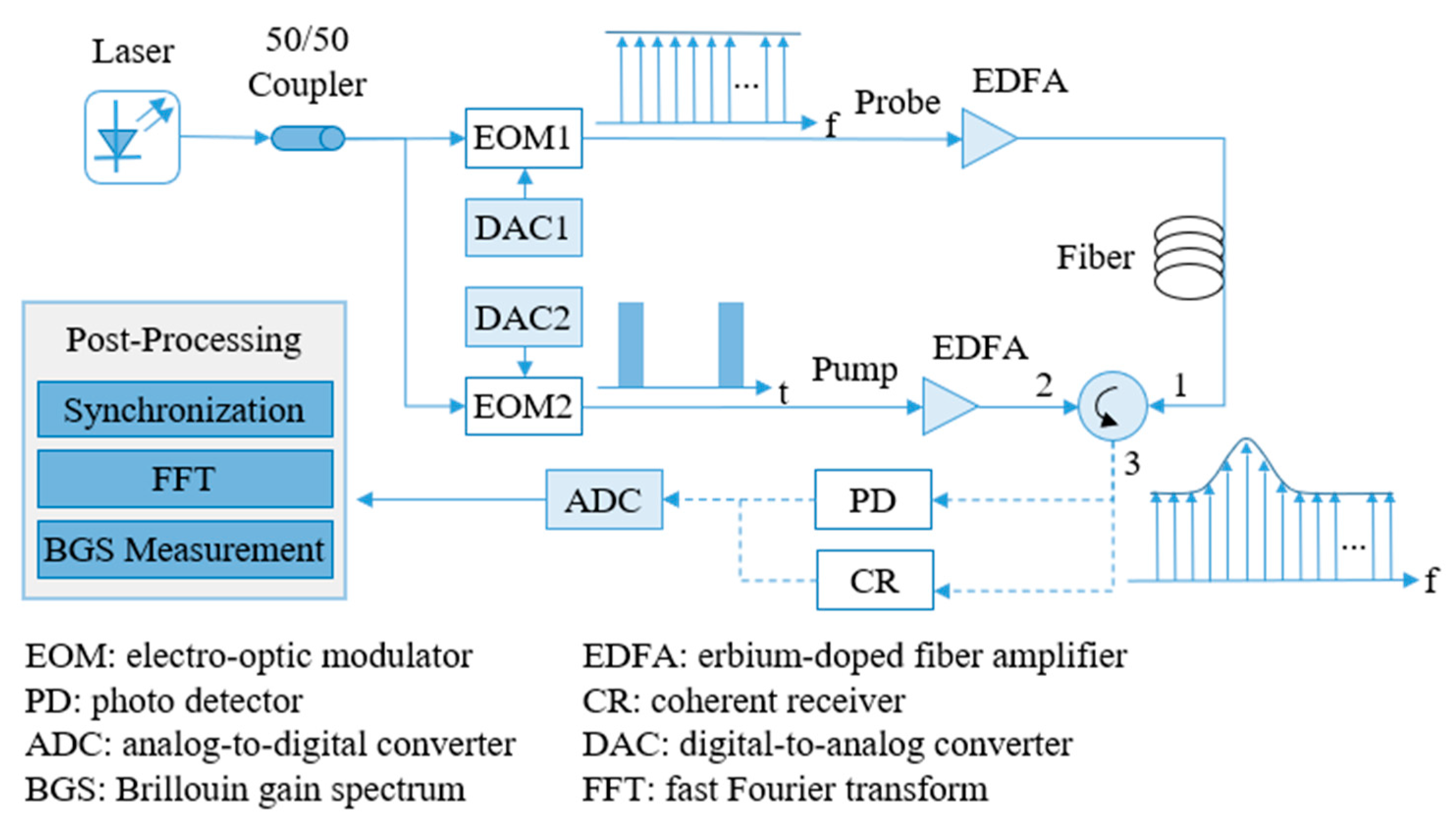
The simplified schematic principle of SF-BOTDA system is shown in
Figure 1, where after the probe with flat spectrum collides with the pump in the optical fiber, part of the energy of the pump is transferred to the probe due to the Brillouin frequency shift (BFS), converting the flat spectrum into a spectrum with a gain peak. The BFS has a linear relationship with temperature and strain, therefore the detection of temperature or strain can be realized via monitoring the BFS [
5,
6]. The probe is a periodic frame sequence modulated by an electro-optic modulator (EOM), which interacts with the pump in sequence and records the BFS, which is organized into each of its independent frames. At the receiver end, after the frame synchronization, fast Fourier transform (FFT), and Brillouin gain spectrum (BGS) measurements, the BFS of different positions can be obtained. It can be seen that in the SF-BOTDA system, frame synchronization is the first step of data processing and a guarantee and premise for subsequent data analysis.
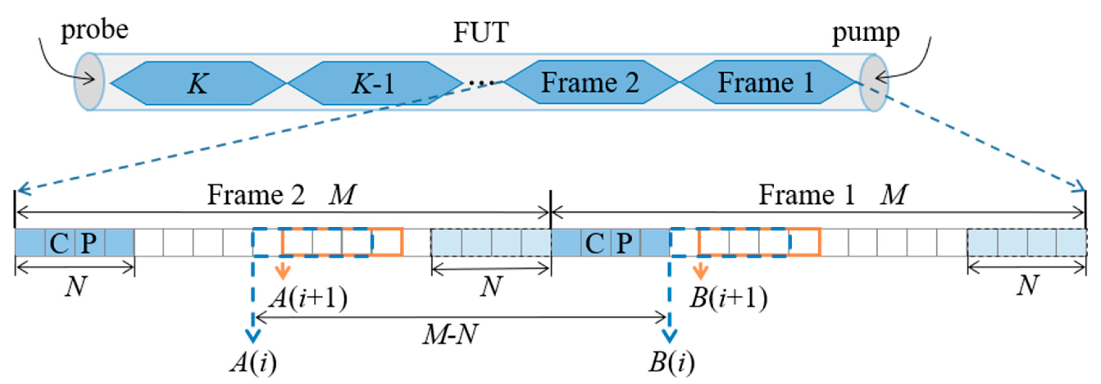
The problem of locating the frame separation position is called frame synchronization. Furthermore, the synchronization algorithms can be divided into data-aided and non-data-aided methods depending on whether additional symbols are needed in the process of synchronization. The basic idea of the data-aided method is the use of a training sequence or pilot signal as an auxiliary to realize synchronization based on the self-correlation of the received sequence or the cross-correlation between the received sequence and local reference sequence. The non-data-aided method constructs a new frame structure by using cyclic prefix (CP) or empty subcarriers to realize synchronization, as shown in
Figure 2. Since CP is a copy of
N sample points of the original frame tail, there is the greatest correlation between them, and the frame separation position can be located correctly by comparing the correlation between sequences of different positions.
In fact, the core idea of synchronization is the same whether a data-aided method or non-data-aided method is adopted, that is, the correlation between sequences of different positions is constantly calculated to find the position with the highest correlation as the result of the synchronization. In this paper, the non-data-aided method with CP will be illustrated as an example.
Mathematically, for a frame with
M sample points,
M times correlations need to be calculated to locate the frame synchronization position, and the correlation of the sequences is measured using a normalized cross-correlation coefficient (NCC). For sequences
A(
i) and
B(
i) in position
i, the NCC is defined as:
where
A(
i,
j) and
B(
i,
j) are the
j-th sample point of sequences
A(
i) and
B(
i), respectively, and
and
are the respective mean values of them, which are defined as:
From Equations (1)–(3), the calculation of
for two sequences with
N samples requires
multiplications and
summations. Furthermore, for the frame shown in
Figure 2,
M times NCC calculations are required for the location of the frame synchronization position; to process this number of calculations, millions of operations are needed, which can be quite a challenge for a real-time BOTDA system. Hence, it is necessary to find out a way to reduce the calculation complexity of the frame synchronization.
2.2. Fast Frame Synchronization Method
In the process of frame synchronization, since the cached sequence A(i+1) and B(i+1) are only one sample delay from A(i) and B(i), respectively, there is a larger amount of computational redundancy between them. Some methods can be taken to avert repeatedly calculating the terms in the nominator and denominator at each calculation step of Equation (1).
Let
,
, and
, such that Equation (1) can be simplified to:
For
, the value of position (
i+1) has the following relationship with the value of position
i:
which can be simplified to:
It can be seen that can be calculated through two multiplications and five summations on the basis of . Compared with the direct calculation method, which requires N multiplications and summations, the computational complexity is significantly reduced.
Similarly, one can derive that:
Substituting Equations (6)–(8) into Equation (1), one can rewrite the
M times NCC calculations for frame synchronization as:
Therefore, in light of Equation (9), it can be seen that the calculation complexity is substantially reduced to
multiplications and
summations. For the
M = 1152 and
N = 128 used in References [
14,
15], using the standard method requires 446,976 multiplications and 1,026,432 summations, while using the proposed method only required 9596 multiplications and 19,307 summations, reducing the calculation amount by about 98%, which makes the real-time frame synchronization in BOTDA possible.
2.3. FPGA Implementation
In order to further improve the real-time performance of the BOTDA system, parallel and pipeline mechanisms of FPGA can be used to reduce the time consumption of data processing [
19,
20,
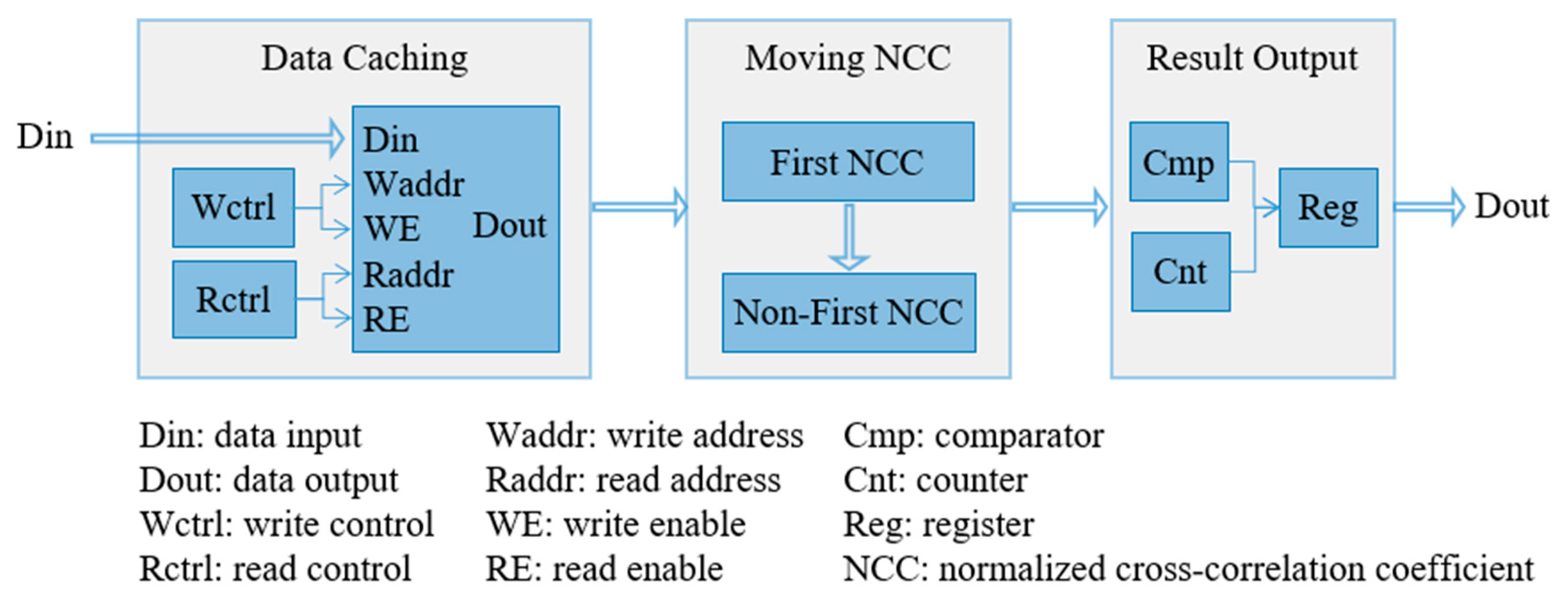
21]. The hardware architecture of the proposed method implemented on an FPGA is shown in
Figure 3, consisting of three parts: (1) data caching module, (2) moving NCC module, and (3) result output module. Among them, the data caching module is used for data access control and format conversion, the moving NCC module calculates the
M times NCC calculations, and the result output module compares the NCC value of each position to find the frame synchronization position.
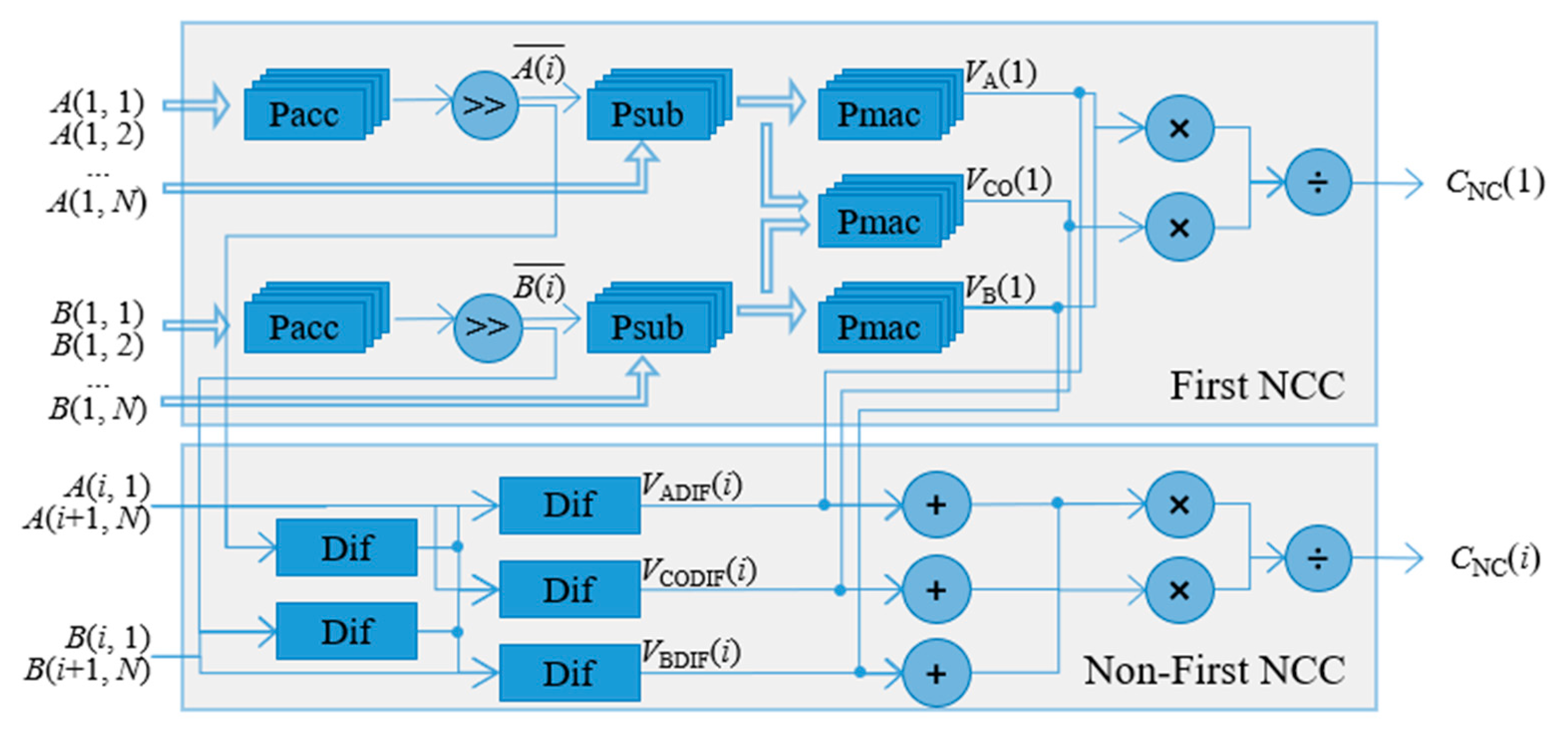
In the moving NCC module, for the purpose of speeding up the frame synchronization, the NCC parallel structure is proposed, as shown in
Figure 4, which consists of two main parts: (1) first NCC and (2) non-first NCC. For the first NCC parts, parallel computation is employed for each calculation step to speed up the real-time frame synchronization. For example, at the step of normalizing the inputted raw data, the parallel subtractor (Psub) that parallelly subtracts the original value of each sequence from their mean that is calculated first with a parallel accumulator (Pacc) and a right-shift operation is implemented. After the Psub, the normalized sequence is ready for the input of a parallel multiply-accumulator (Pmac) to calculate
,
, and
, respectively. Then, the final result of
can be obtained by using Equation (9). For the non-first NCC calculation, it is much easier than the first NCC since it just requires the calculation of the values of
,
, and
. By reusing the last time results of
,
, and
, it is easy to obtain the value of the non-first NCC according to Equation (9). The above steps adopt a pipelining mechanism, where under the control of clock (CLK), sequence data can be continuously inputted and the calculation result can be continuously outputted after a certain initial delay.
3. Experimental Results and Analysis
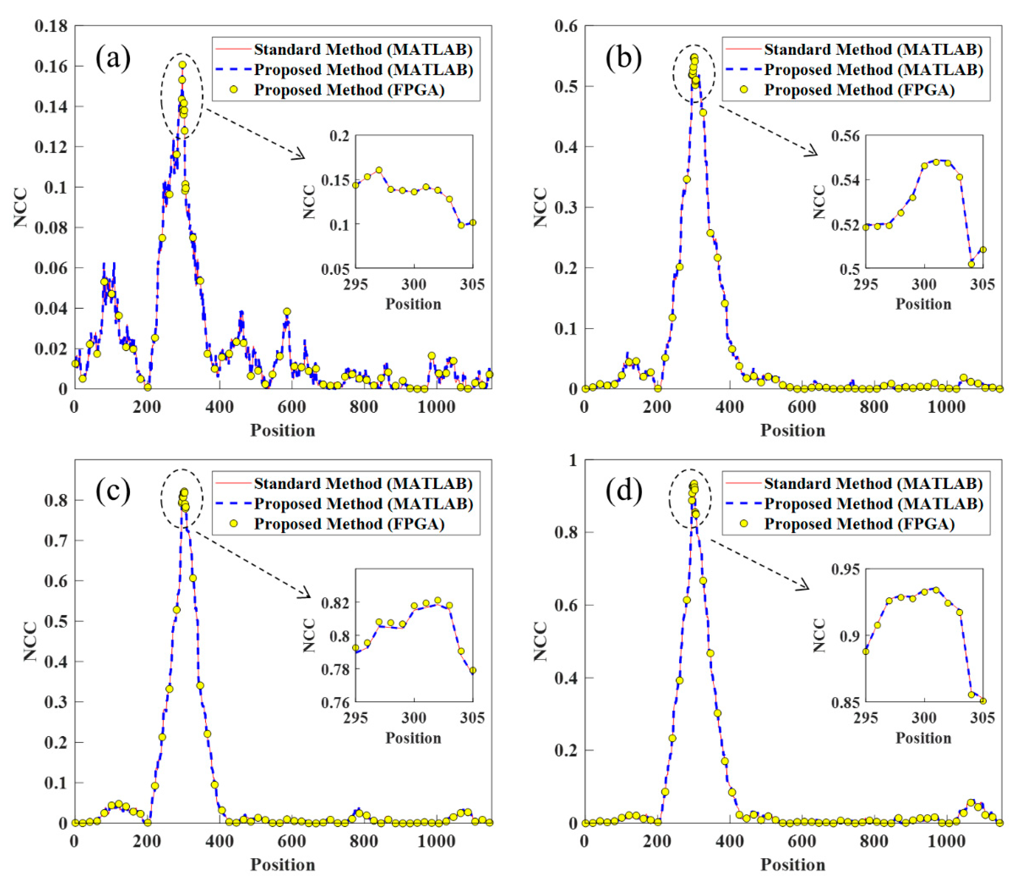
To compare the accuracy of computation between the proposed method and the standard frame synchronization method, random data with different signal to noise ratios (SNRs) with
M = 1152 and
N = 128 were input to the system. Under the situations of SNR adjusted from 5 dB to 20 dB changing with 5 dB steps, as shown in
Figure 5, the proposed method was consistent with the standard method for calculating the NCC value of the different position in MATLAB (R2017b, 64-bit, MathWorks, NATICK, MA, U.S.), which verified the correctness of the proposed method. Furthermore, it can be seen that the NCC value of different positions had a slight deviation between the platforms of MATLAB and FPGA, which was inevitable because of the finite word-length effect of division and square root operation in FPGA implementation. Furthermore, the zoomed images show that the position of the maximum NCC was the same between different platforms and methods, indicating that both the proposed fast frame synchronization method and the FPGA implementation could locate the frame separation position correctly.
The comparison of the running time between the proposed fast frame synchronization method and the standard method on different platforms is shown in
Table 1. It can be seen that in the MATLAB platform, compared with the standard method, which needed 9227 μs for the frame synchronization, the proposed method only took 55 μs, which reduced the running time by over 99.4%. Further, the FPGA implementation of the proposed method only needed 4.1 μs to perform the same operation, and the time performance was improved by 13.41 times compared with software implementation, which indicates that the parallel processing and pipeline mechanism could further accelerate the frame synchronization of BOTDA. The experimental result of
Table 1 shows that the proposed method and FPGA implementation could effectively reduce the time consumption required for frame synchronization and lay a foundation for the BOTDA system in the field with high real-time requirements.
Table 2 shows the influence of the different methods used to complete frame synchronization on the real-time performance of the BOTDA system. In order to realize real-time BOTDA, the parallel and pipeline mechanisms of FPGA were adopted to achieve the rate consistency of data acquisition and data processing. As a result, for the implemented BOTDA system, the processing result of input sensor data could be continuously output after the initial delay. Note that since the subsequent piecewise data processing could only be carried out after the completion of frame synchronization in a pipelined manner, the initial delay consisted of the time consumed by frame synchronization and the data processing of the first frame. As shown in
Table 2, the initial delay was mainly limited by the frame synchronization when the standard synchronization method was adopted, and it could be significantly reduced if we used the proposed synchronization method, which meant the real-time performance of the BOTDA system was better.


