Article

Near-IR Plasmons in Micro and Nanoparticles with a Semiconductor Core

by
Fahime Seyedheydari
1,
Kevin Conley
1 and
Tapio Ala-Nissila
1,2,*
1
Department of Applied Physics, QTF Centre of Excellence, Aalto University School of Science, P.O. Box 11100, FI-00076 Aalto, Finland
2
Interdisciplinary Centre for Mathematical Modelling, Department of Mathematical Sciences, Loughborough University, Loughborough, Leicestershire LE11 3TU, UK
*
Author to whom correspondence should be addressed.
Photonics 2020, 7(1), 10; https://doi.org/10.3390/photonics7010010
Submission received: 5 December 2019 / Revised: 15 January 2020 / Accepted: 15 January 2020 / Published: 17 January 2020

Abstract

:
We computationally study the electromagnetic response of semiconductor micro and nanoinclusions for realizing highly reflective, plasmonically enhanced coatings in the visible and infrared regime. We first examine the influence of oxide coatings on the Mie resonances of microparticles of low-bandgap semiconductors (Si and Ge) in the near-IR regime. We then study the influence of a semiconducting core on the localized surface plasmon resonances of Si@Ag and Ge@Ag core@shell nanoparticles. Our results show a strong interaction between the resonances of the plasmonic Ag shell and the semiconducting core material which allows tuning of the electromagnetic response for near-IR applications.

1. Introduction

Metal nanoparticles exhibit collective oscillations of surface conduction electrons in an incident electromagnetic field. The localized surface plasmon resonances (LSPRs) of metallic systems have garnered widespread attention given their high free carrier concentration, typically on the order of 10 22 cm 3 [1]. The wavelength of the LSPR depends on the material, size, shape of nanoparticles and its surroundings. The LSPR properties of silver nanoparticles are exploited in applications such as surface-enhanced Raman scattering [2], optical fiber biosensors [3], and sensing platforms [4]. Yet, metals suffer losses in the visible and near-IR regimes [5].
Recently, doped conventional semiconductors such as silicon and germanium have been explored as candidates to supplement classical metals for plasmonics and nanophotonic applications in the near-IR [1,6,7]. Dopants change the electronic structure and influence the free charge carrier concentration by creating energy levels in the bandgap [8]. The minimum carrier concentration to obtain metal-like optical properties in the near-IR for semiconductors, such as silicon, is about 10 21 cm 3 [9].
Composites containing undoped low bandgap semiconductor microinclusions have been shown to strongly reflect IR even at small volume fractions [10]. Further, reflectance of up to 90 % were observed at specific wavelengths [11] and the composites could act as thermal insulators or to improve the absorption of ultra-thin solar cells in the near-IR [12]. Conventional metallic plasmonic particles in contact with an absorbing semiconductor material such as Si has been proposed to enhance broadband absorption enhancements in solar cells [13]. The interaction of nanoparticles with light is well described by the Lorentz-Mie theory, and the scattering of a core@shell particle has an analytical solution [14]. In general, the scattered field is a superposition of normal modes, each weighted by the appropriate coefficients ( a n or b n ) [15,16]. The material properties of the particle are described by the complex dielectric function. The free electrons within metals, such as silver, can be approximated as a gas of noninteracting electrons using the classical Drude free electron model. The Drude model is a classical theory that does not include any quantum effects and it ignores long-range interactions between electrons and ions, and yet it provides accurate qualitative information [17].
The LSPR of particles containing a metallic shell yields a splitting of the LSPR into a symmetric or “bonding” and an antisymmetric or “antibonding” plasmon [18]. The thickness of a metallic shell controls the interaction between the sphere and cavity plasmons. Adding a dielectric material to plasmonic structures creates another way to control the redshift or blueshift of magnetic and electric modes and optimize their scattering efficiency [19,20]. Introducing a high refractive index oxide core redshifts the symmetric dipole surface plasmon resonance mode of a hollow metal shell [21]. In this work, we study the behavior of these modes by adding a high refractive index semiconductor core to plasmonic nanoparticles in a core@shell system. Additional resonances generated by the semiconductor core supplement and interact with those of a bare or hollow metallic particle. The participation from an active core expands the tunability of the electromagnetic response beyond that of classical metals.
In this paper, we focus on the influence of semiconductor core on a silver shell in nano and micron size spherical core@shell particles in an external electromagnetic field. The dielectric response of these nanoparticles will be calculated using Mie theory and polarizability equations. We first consider core@shell particles with Si as the core material, coated with oxide dielectrics such as TiO 2 , SiO 2 , or ZrO 2 . After this, we consider semiconductors as the active core coated with a metallic layer. As a reference, we use the case of hollow Ag nanoparticles which can be treated with the Drude theory and the hybridization model.

2. Materials and Methods

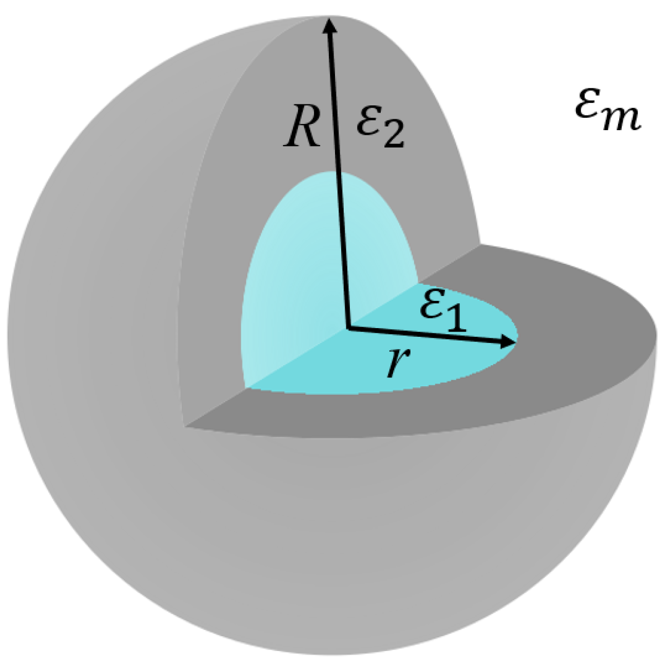
2.1. Mie Theory for Core@Shell Particles

We consider a sphere of inner radius r which is coated with a layer of uniform thickness R r as shown schematically in Figure 1. An analytical solution to Maxwell’s equations yields the dielectric response of the core@shell particle in an external electromagnetic field in the form of the electric and magnetic Mie coefficients a n and b n , respectively [14]. If the permeability of the particle and the surrounding medium are assumed to be equal, then the Mie coefficients for a core@shell sphere are given by
a n = ψ n ( y ) ψ n ( m 2 y ) A n χ n ( m 2 y ) m 2 ψ n ( y ) ψ n ( m 2 y ) A n χ n ( m 2 y ) ξ n ( y ) ψ n ( m 2 y ) A n χ n ( m 2 y ) m 2 ξ n ( y ) ψ n ( m 2 y ) A n χ n ( m 2 y ) ;
b n = m 2 ψ n ( y ) ψ n ( m 2 y ) B n χ n ( m 2 y ) ψ n ( y ) ψ n ( m 2 y ) B n χ n ( m 2 y ) m 2 ξ n ( y ) ψ n ( m 2 y ) B n χ n ( m 2 y ) ξ n ( y ) ψ n ( m 2 y ) B n χ n ( m 2 y ) ,
where
A n = m 2 ψ n ( m 2 x ) ψ n ( m 1 x ) m 1 ψ n ( m 2 x ) ψ n ( m 1 x ) m 2 χ n ( m 2 x ) ψ n ( m 1 x ) m 1 χ n ( m 2 x ) ψ n ( m 1 x ) ,
and
B n = m 2 ψ n ( m 1 x ) ψ n ( m 2 x ) m 1 ψ n ( m 2 x ) ψ n ( m 1 x ) m 2 χ n ( m 2 x ) ψ n ( m 1 x ) m 1 ψ n ( m 1 x ) χ n ( m 2 x ) ,
and ψ n ( x ) and ξ n ( x ) are Riccati-Bessel functions [15]. The size parameters are given by x = 2 π n m r / λ and y = 2 π n m R / λ . m 1 and m 2 are the refractive indices of the core and coating relative to the surrounding medium ( n m ). The order of the dielectric resonance is represented by n, where the dipole is n = 1 , the quadrupole is n = 2 , the octupole n = 3 , and so on. The efficiency of scattering, extinction and absorption [15] can be calculated as
Q sca = 2 y 2 n = 1 N ( 2 n + 1 ) ( | a n | 2 + | b n | 2 ) ;
Q ext = 2 y 2 n = 1 N ( 2 n + 1 ) Re { a n + b n } ,
and
Q abs = Q ext Q sca .

2.2. Polarizability of Core@Shell Shapes

The emergence of LSPRs in metallic nanoparticles can be well approximated by the static polarizability of such objects in an external electric field. The quasistatic polarizability of a homogeneous sphere ( ε 1 ) coated with a shell ( ε 2 ) in a dielectric medium ( ε m ) is given by [15]
α = V ( ε 2 ε m ) ( ε 1 + 2 ε 2 ) + f ( ε 1 ε 2 ) ( ε m + 2 ε 2 ) ( ε 2 + 2 ε m ) ( ε 1 + 2 ε 2 ) + f ( 2 ε 2 2 ε m ) ( ε 1 ε 2 ) ,
where f is the fraction of the total particle volume occupied by the core. The resonance condition for a hollow sphere in vacuum ( ε 1 = ε m = 1 ) can be obtained by minimizing the denominator of Equation (8). Then there are two roots to Equation (8) given by
ε 2 ± = ( 5 + 4 f ) ± 3 1 + 8 f 4 4 f .
These roots are known as the symmetric ( ε 2 ) and antisymmetric ( ε 2 + ) modes [15]. If f is small the symmetric and the antisymmetric resonances are approximately at ε 2 = 2 and ε 2 + = 1 / 2 , respectively.
The computer codes used are available upon request.

3. Results and Discussion

In this section, we will examine the influence of a semiconductor core on the plasmon hybridization of a Ag shell. First as a reference, in Section 3.1 we calculate the near-IR ( λ = 1 to 5 μ m) behavior of spherical Si particles different oxides (SiO 2 , TiO 2 , and ZrO 2 ) with a refractive index of the medium equal to 1.5. The core radius is fixed at 0.6 μ m and the total radius grows from 0.6 to 1.1 μ m. Then in Section 3.2, we show how a semiconductor core (Si, Ge) influences the symmetric and antisymmetric modes of a metallic coating. The core radius is fixed at 30 nm and the total particle radius is varied from 30 to 70 nm. As a reference, the simple case of a hollow Ag spherical shell with a total radius of 20 nm is considered in the visible to near-IR region ( λ = 0.3 to 1.8 μ m). The medium has a constant refractive index of either 1.5 or 2.4 to represent either a silica or titanium dioxide matrix. The plasmon hybridization model is briefly introduced to qualitatively explain the hybridized modes.
Apart from the shell permittivity, the permittivities of the core and medium play an important role in determining the optical response of the core@shell system. Their strong effects on the plasmon modes are demonstrated below.

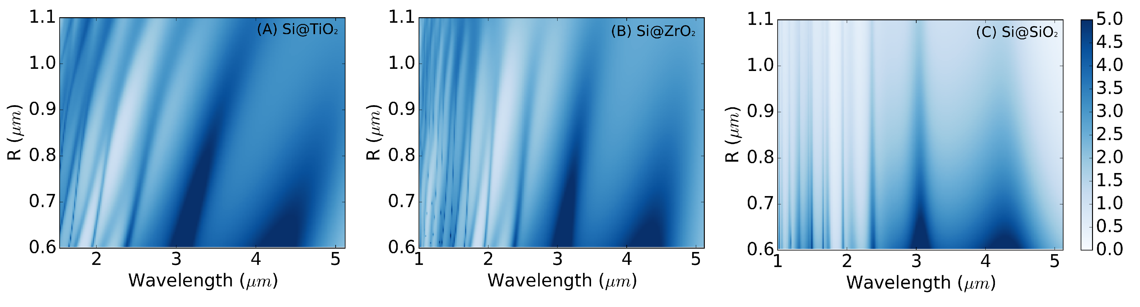
3.1. Semiconductor@Oxide Microparticles

For near-IR applications, i.e., λ = 1 to 5 μ m, we consider spherical semiconductor microparticles coated with a dielectric shell and surrounded by a non-absorbing insulating medium with constant refractive index of 1.5 . The core material is a low band gap semiconductor, either Si (bandgap 1.11 eV at T = 300 K) or Ge (bandgap 0.66 eV at T = 300 K) [22]. The particles are coated with either SiO 2 , TiO 2 , or ZrO 2 . The shell is chosen to be low- κ or high- κ materials and their refractive indices vary from approximately 1 to 2.6 in the given regime. The bulk complex indices of refraction were obtained from Palik [23] or Wood [24]. The refractive indices of birefringent TiO 2 are averaged over the ordinary and the extraordinary directions. To represent IR grade fused SiO 2 , the extinction coefficient of SiO 2 is assumed to be zero below 3.5 μ m. The extinction coefficient of ZrO 2 was assumed to be zero.
The extinction efficiency data Q ext of a Si particle coated with an oxide (TiO 2 , ZrO 2 , or SiO 2 ) in the near-IR regime are presented in Figure 2A–C, respectively. The core radius is fixed at 0.6 μ m and the total particle radius, given along the y axis, increases up to 1.1 μ m. The intensity of blue color indicates the magnitude of Q ext and the maximum values, corresponding to the Mie resonances, are dark blue. The panels within Figure 2 illustrate the effect of different shell materials on the extinction efficiency. As the oxide is added, the magnitude and wavelength of the maximum intensity changes. Figure 2A,B show that the Mie resonances of Si@TiO 2 and Si@ZrO 2 redshift with increasing total particle size. By comparison, the resonances of SiO 2 coated particles in Figure 2C do not shift. The shifting is due to the relative refractive index of the shell to the medium, m 2 . The resonances of the particle coated with SiO 2 do not shift because m 2 is approximately equal to unity and the Mie coefficients of the coated sphere reduce to those for a sphere of radius r and relative refractive index of the core m 1 [15]. For the TiO 2 and ZrO 2 coated particles m 2 > 1 and the resonances redshift with increasing shell thickness. For example, the resonance at 3.06 μ m in the bare Si particle shifts to 3.25 μ m and 3.37 μ m when coated with a 0.2 μ m layer of ZrO 2 and TiO 2 , respectively.

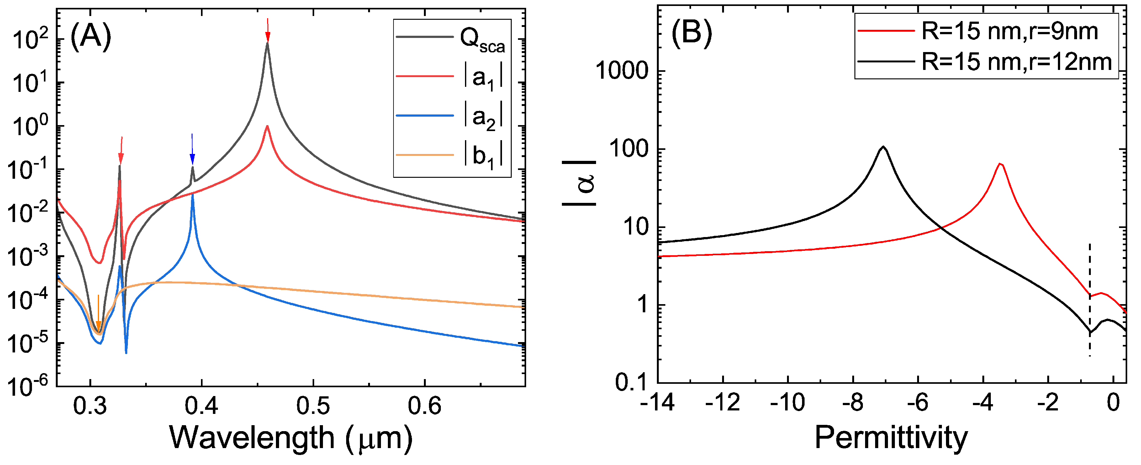
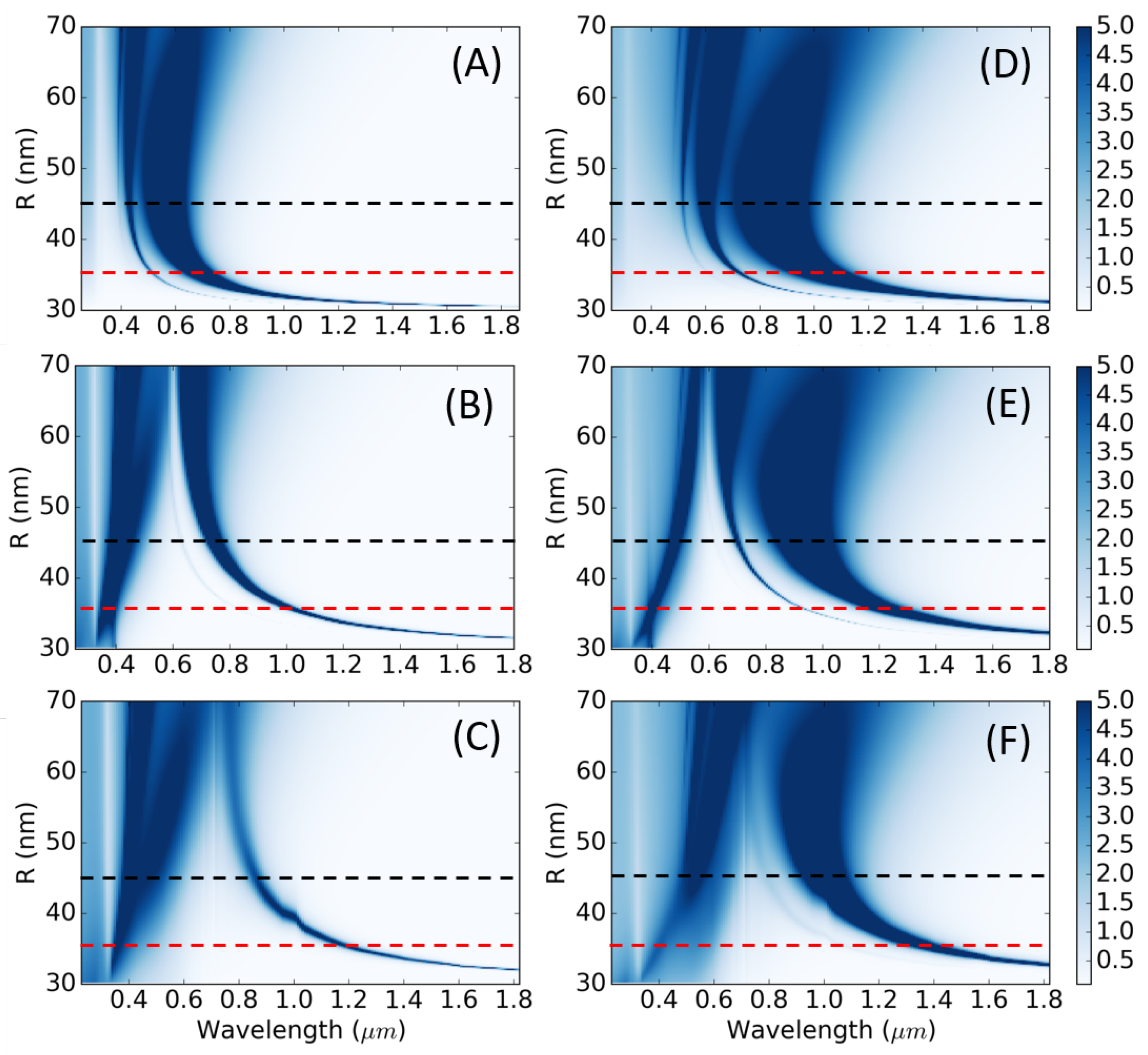
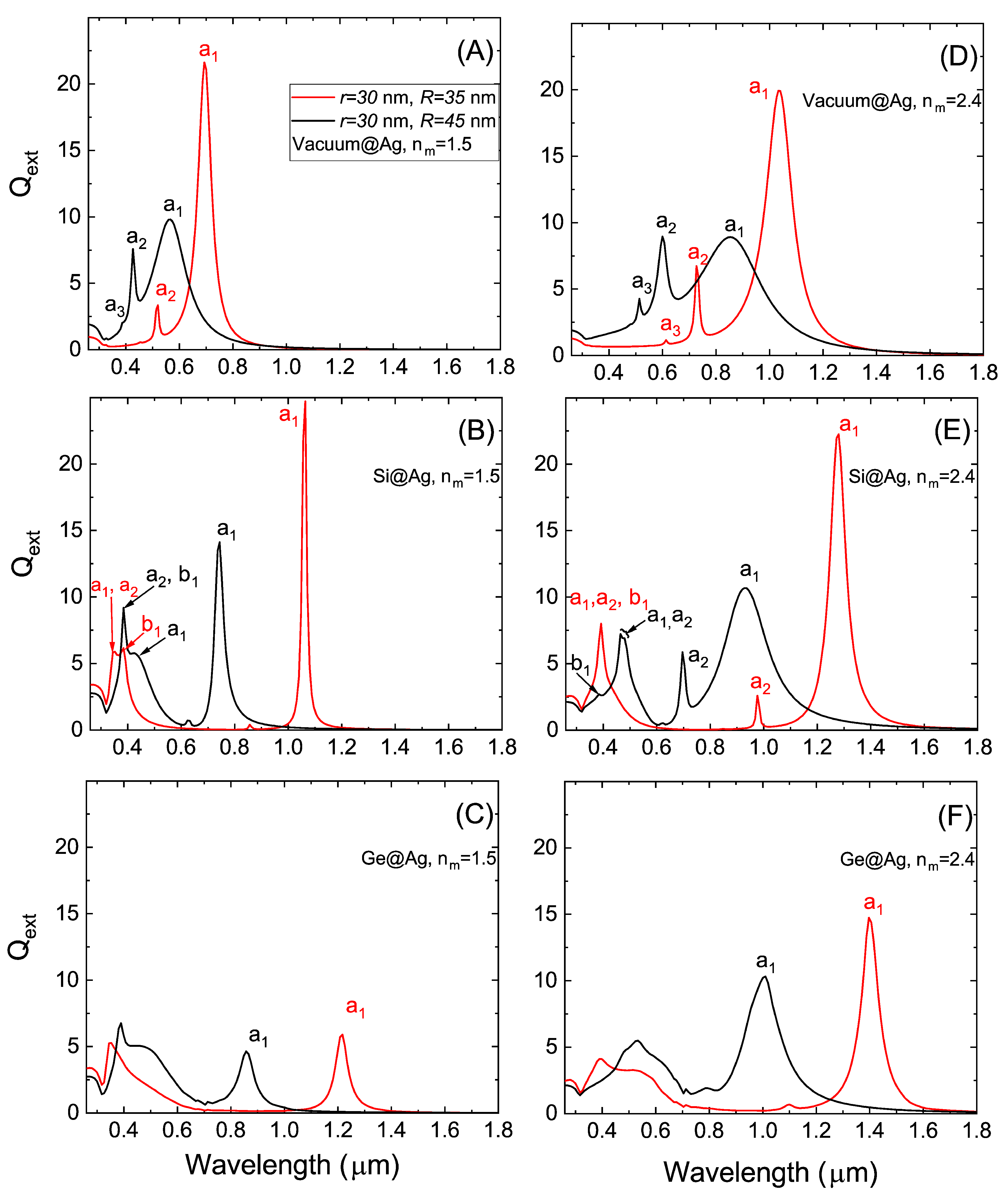
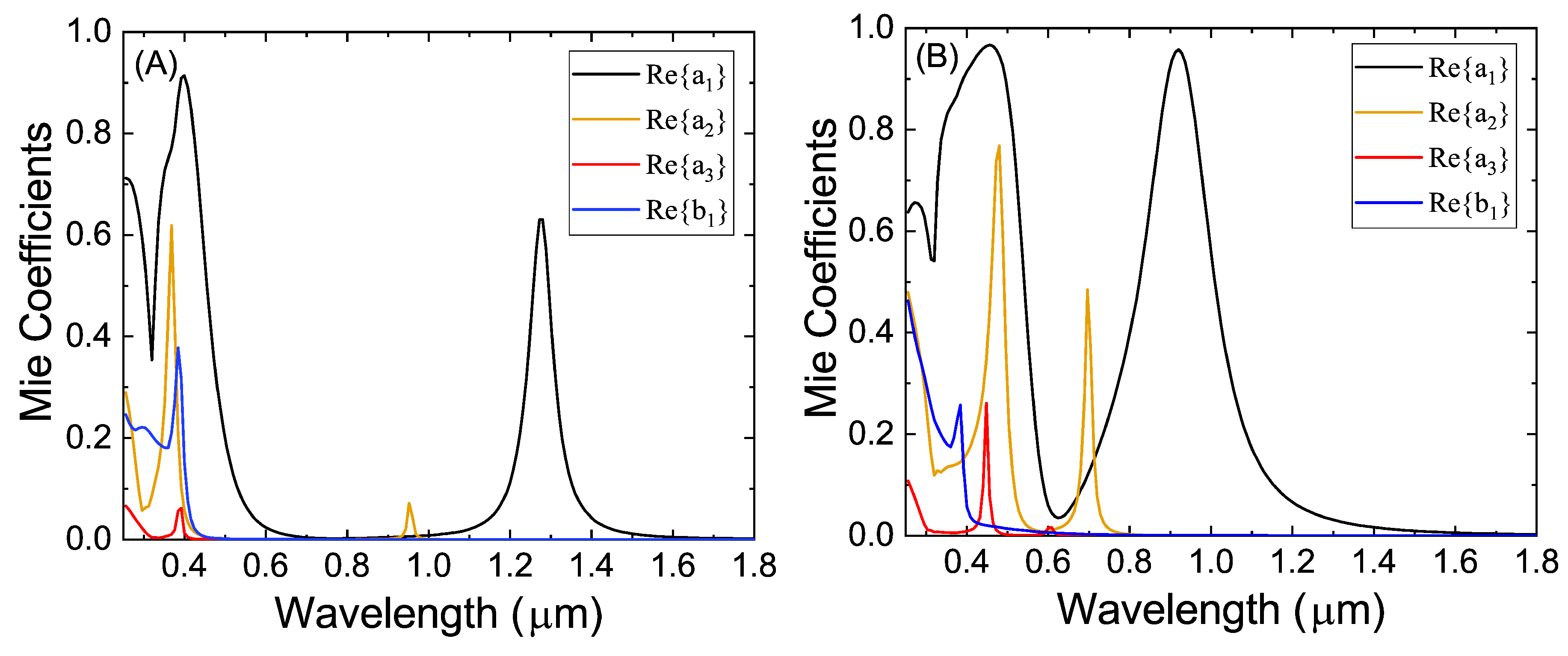
3.2. Semiconductor@Metallic Nanoparticles

In this subsection, we consider nanoparticles with a silver shell and a semiconductor (Si or Ge) core. The resonances of semiconductor@metallic particles will be contrasted to those of a hollow silver shell. The plasmon modes from the silver shell are influenced by the particle dimensions and the permittivity of the surrounding core and the medium. In addition, there are additional contributions from the semiconductor core which interacts with the plasmon modes hybridized by the silver shell.
Confinement of a metal into different shapes produces modes which can be described as hybridized plasmons. A hollow metallic nanoshell is a well-known example of the plasmon hybridization model [18,25]. As an example, we consider a vacuum@silver particle with a total particle radius of R = 20 nm, core radius r = 16 nm and the refractive index of the surrounding medium is 1. The complex refractive index for bulk silver was obtained from experimental data from Johnson and Christy [26]. The scattering efficiency has a global maximum in Q sca at λ = 458 nm as seen in the black line in Figure 3A. Additionally, there are local maxima at 390 and 325 nm. The peaks of Q sca correspond to maxima in the Mie coefficients, a 1 and a 2 , and are indicated by vertical arrows.
The LSPR hybridization in a metallic shell can be described by the interaction between the inner and outer shell resonances. The resonance frequencies for LSPRs of a core@shell nanoparticle in the hybridization model are given by
ω l ± 2 = ω p 2 2 1 ± 1 2 l + 1 1 + 4 l ( l + 1 ) r R 2 l + 1 ,
where ω p is the surface plasmon energy, for l = 1 , 2 , 3 . . . [18]. The ω l + and ω l modes correspond to the antisymmetric and symmetric modes, respectively.
Increasing the core size changes the strength of the interaction by decreasing the distance between the inner and outer surfaces of the shell. Figure 3B illustrates the absolute value of the polarizability for two core radii and a fixed total radius of 15 nm. In the small core, r = 9 nm, the broad symmetric mode appears at ε = 3.45 and in the larger core, r = 12 nm, it appears at ε = 7.08 . Because the permittivity of Ag is a decreasing function of λ , it is redshifted with increasing hollow core. The antisymmetric modes are weaker and narrower than the symmetric one [27]. A minimum of ε = 1 / 2 is known as the Fröhlich mode and is indicated by a dashed line in Figure 3B. This mode can be obtained from the polarizability of the nanovoid and is independent of the core size.
Next, the extinction efficiencies are calculated for a sphere with a fixed core radius of 30 nm and Ag shell thickness up to 40 nm. The refractive index of the surrounding medium is 1.5 in Figure 4A–C and 2.4 in Figure 4E–G. The hollow Ag shell, ε 1 = 1 , is given in panels A and D. The core material is Si in panels B and E and Ge in panels C and F. The Q ext of core@shell particles with an inner radius of 30 nm and outer radii of either 35 nm or 45 nm are explicitly given in Figure 5 and are indicated by the horizontal dotted lines in Figure 4.
For a fixed core radius as considered here, the ratio of the radii r / R is reduced by increasing the total radius. According to Equation (10) the symmetric modes (at higher wavelengths) blueshift and the antisymmetric modes redshift with decreasing r / R . This situation is in contrast to bare silver particles which have no hybridization and redshift with increasing size. Thus in panel A of Figure 4 the plasmon modes blueshift when the total particle radius increases from R = 35 to R = 45 nm. The same shift is represented in panel A of Figure 5. For example, the dipolar symmetric mode broadens and shifts from λ = 694 to λ = 563 nm and its magnitude diminishes when the total particle radius increases from R = 35 to R = 45 nm. In addition, the antisymmetric modes have a slight redshift although they are not visible in this panel because their magnitudes are negligible. Rather this effect can be observed in terms of the polarizability as a function of permittivity in Figure 3B.
The effect of the core material on the plasmon hybridization of the Ag shell and optical properties of the nanoparticles is observed by comparing the rows in Figure 4 and for the specific dimensions in Figure 5. For both the Si and Ge core, the magnitudes of the antisymmetric modes have increased such that the modes are visible in contrast to the hollow Ag particle discussed above. The antisymmetric modes redshift and broaden for increasing total particle size. For a given size, the antisymmetric modes of Ge@Ag are redshifted from those of Si@Ag (cf. Figure 4B,C). For example, when R = 45 nm the dipolar electric mode occurs as part of a composite mode at λ = 389 nm in Ge@Ag and at λ = 383 nm in Si@Ag. The permittivity of Si and of Ge at these wavelengths is ϵ 1 14.01 and ϵ 1 21.73 , respectively, and thus increasing the permittivity of the core redshifts the mode. Similar shifts are observed in the symmetric modes. For example, the dipolar mode for R = 45 nm (black lines) occurs at λ = 740 nm and λ = 858 nm for Si@Ag and Ge@Ag in panels B and C of Figure 5, respectively.
The core permittivity driven shifts of the hybridized plasmon modes of the silver shell can be analyzed using an expansion of Mie coefficients [28] and the plasmon hybridization model [29]. Previously, it has been shown for small core@shell particles with thick shells that when the core permittivity ( ϵ 1 ) is larger than 4 the plasmon resonance conditions are [28]
ϵ + = 2 + 6 ϵ 1 + 2 ϵ 1 4 f ; ϵ = ϵ 1 2 3 2 ϵ 1 ϵ 1 + 2 ϵ 1 4 f .
The symmetric and the antisymmetric modes of the silver shell redshift with an increasing core permittivity.
In addition, the influence of the core permittivity can be explained using the hybridization model in which the symmetric and antisymmetric modes are the result of the interaction between the cavity, ω C , and sphere plasmons, ω S [30]. The strength of the hybridization depends on the difference in their energies, which are given by ω C ( ε 1 , ε J ) = ω p l + 1 l ε 1 + ( l + 1 ) ε J and ω S ( ε m , ε J ) = ω p l ( l + 1 ) ε m + l ε J and where ϵ J is the background permittivity of the shell [29]. In this case, the effects of background permittivity are neglected such that ε J = 1 . The energy of the cavity plasmon decreases for larger core permittivity. Thus, as the core changes from Si to Ge in Figure 4B,C, the antisymmetric and symmetric modes redshift due to the weakened hybridization interaction.
There is a large impact on the position and width of both the symmetric and antisymmetric modes in different media. Comparing the left and right columns of Figure 4 shows the effect of increasing the permittivity of the medium. For example, the symmetric mode of Si@Ag at R = 45 nm (black lines) shifts from λ = 741 nm to λ = 930 nm between panels B and E of Figure 5. Similarly, the antisymmetric mode shifts although to a lesser extent (from λ = 407 nm to λ = 471 nm when the refractive index of the medium is changed from 1.5 to 2.4 ). The redshift is also observed for the other core materials in panels A,D and C,F. When the permittivity of the medium increases the cavity plasmon energy does not change, but the spherical plasmon, ω S ( ε m ) , is shifted to lower energies. Consequently, the antisymmetric and symmetric modes are more separated energetically when the refractive index of the medium is 2.4.
The resonances from the semiconductor core participate in the response of the core@shell particle and are revealed in Figure 4 and Figure 5. The Mie coefficients of the two Si@Ag particles in Figure 5E are provided in Figure 6. The energies and intensities of the symmetric and antisymmetric plasmons are captured by the first three electric modes described above. In addition, the antisymmetric mode is enhanced by the dipolar magnetic contribution from Si (c.f. Figure 5E, red curve and Figure 6A). The enhancement is lost in the larger particle as the near degeneracy is lifted (c.f. Figure 5E, black curve and Figure 6B). While the antisymmetric electric modes redshift with increasing the total particle radius, the real part of b 1 blueshifts from λ = 393 nm to λ = 383 nm. The resonances from the core are influenced by the surrounding shell and medium.

4. Conclusions

We have studied the extinction efficiencies from spherical particles with a semiconductor (Si or Ge) core and an Ag shell in the visible and near-IR using Mie theory. The semiconductor core both influences the dielectric environment of the hybridized plasmons of the metallic shell and produces Mie resonances. There are marked changes to the optical properties of a hollow Ag particle such as a shifting of the plasmon energies and a magnification of the antisymmetric plasmon. These effects were explained using the plasmon hybridization model and an expansion of the Mie coefficients.
In the semiconductor@metal particles considered, the multipole plasmonic modes redshifted when either the core or the medium permittivity was increased. The changes were rationalized according to the shift in the cavity and sphere plasmon within the plasmon hybridization model. In addition, the symmetric and antisymmetric plasmon energies diverge in thin shells. The scattering of semiconductor@metallic particles is determined by its complex permittivity and geometry. Further, the interaction of the incident electromagnetic radiation with the semiconductor in the core produces Mie resonances which are influenced by its surroundings. Adding an active core within a metallic particle offers new tunability and extends their capability to realize highly reflective, plasmonically enhanced coatings in the visible and infrared regime.

Author Contributions

This article is the collaborative development of all authors. F.S. investigated, analyzed, and wrote the original draft. K.C. contributed to the investigation, analysis, methodology, and editing. T.A.-N. contributed to the concept, design, and revision of the manuscript. All authors have read and agreed to the published version of the manuscript.

Funding

This work was performed as part of the Academy of Finland project 314488 and QTF Centre of Excellence program (project 312298).

Acknowledgments

We acknowledge computational resources provided by CSC—IT Center for Science (Finland)—and by the Aalto Science—IT project (Aalto University School of Science).

Conflicts of Interest

The authors declare no conflict of interest.

References

  1. Agrawal, A.; Cho, S.H.; Zandi, O.; Ghosh, S.; Johns, R.W.; Milliron, D.J. Localized surface plasmon resonance in semiconductor nanocrystals. Chem. Rev. 2018, 118, 3121–3207. [Google Scholar] [CrossRef]
  2. Lu, L.; Kobayashi, A.; Tawa, K.; Ozaki, Y. Silver nanoplates with special shapes: controlled synthesis and their surface plasmon resonance and surface-enhanced Raman scattering properties. Chem. Mater. 2006, 18, 4894–4901. [Google Scholar] [CrossRef]
  3. Chen, J.; Shi, S.; Su, R.; Qi, W.; Huang, R.; Wang, M.; Wang, L.; He, Z. Optimization and application of reflective LSPR optical fiber biosensors based on silver nanoparticles. Sensors 2015, 15, 12205–12217. [Google Scholar] [CrossRef] [PubMed]
  4. Aslan, K.; Wu, M.; Lakowicz, J.R.; Geddes, C.D. Fluorescent core- shell Ag@SiO2 nanocomposites for metal-enhanced fluorescence and single nanoparticle sensing platforms. J. Am. Chem. Soc. 2007, 129, 1524–1525. [Google Scholar] [CrossRef] [PubMed]
  5. West, P.R.; Ishii, S.; Naik, G.V.; Emani, N.K.; Shalaev, V.M.; Boltasseva, A. Searching for better plasmonic materials. Laser Photonics Rev. 2010, 4, 795–808. [Google Scholar] [CrossRef] [Green Version]
  6. Naik, G.V.; Boltasseva, A. Semiconductors for plasmonics and metamaterials. Phys. Status Solidi 2010, 4, 295–297. [Google Scholar] [CrossRef] [Green Version]
  7. Paniagua-Domínguez, R.; López-Tejeira, F.; Marqués, R.; Sánchez-Gil, J.A. Metallo-dielectric core–shell nanospheres as building blocks for optical three-dimensional isotropic negative-index metamaterials. New J. Phys. 2011, 13, 123017. [Google Scholar] [CrossRef]
  8. Mendelsberg, R.J.; Garcia, G.; Li, H.; Manna, L.; Milliron, D.J. Understanding the plasmon resonance in ensembles of degenerately doped semiconductor nanocrystals. J. Phys. Chem. 2012, 116, 12226–12231. [Google Scholar] [CrossRef]
  9. Naik, G.V.; Shalaev, V.M.; Boltasseva, A. Alternative plasmonic materials: beyond gold and silver. Adv. Mater. 2013, 25, 3264–3294. [Google Scholar] [CrossRef]
  10. Tang, J.; Thakore, V.; Ala-Nissila, T. Plasmonically Enhanced Reflectance of Heat Radiation from Low-Bandgap Semiconductor Microinclusions. Sci. Rep. 2017, 7, 5696. [Google Scholar] [CrossRef] [Green Version]
  11. Conley, K.; Thakore, V.; Ala-Nissila, T. Plasmonically Enhanced Spectrally-Sensitive Coatings for Gradient Heat Flux Sensors. In Proceedings of the 2018 Progress in Electromagnetics Research Symposium (PIERS-Toyama), Toyama, Japan, 1–4 August 2018; pp. 2435–2441. [Google Scholar]
  12. Atwater, H.A.; Polman, A. Plasmonics for improved photovoltaic devices. Nat. Mater. 2010, 9, 205. [Google Scholar] [CrossRef] [PubMed]
  13. Pala, R.A.; White, J.; Barnard, E.; Liu, J.; Brongersma, M.L. Design of plasmonic thin-film solar cells with broadband absorption enhancements. Adv. Mater. 2009, 21, 3504–3509. [Google Scholar] [CrossRef]
  14. Aden, A.L.; Kerker, M. Scattering of electromagnetic waves from two concentric spheres. J. Appl. Phys. 1951, 22, 1242–1246. [Google Scholar] [CrossRef]
  15. Bohren, C.F.; Huffman, D.R. A Potpourri of Particles. In Absorption and Scattering of Light by Small Particles; John Wiley & Sons: Hoboken, NJ, USA, 1983; pp. 181–183. [Google Scholar]
  16. Kreibig, U. Electronic properties of small silver particles: The optical constants and their temperature dependence. J. Phys. Met. Phys. 1974, 4, 999. [Google Scholar] [CrossRef]
  17. Kittel, C. Introduction to Solid State Physics; Wiley: New York, NY, USA, 1976. [Google Scholar]
  18. Prodan, E.; Radloff, C.; Halas, N.J.; Nordlander, P. A hybridization model for the plasmon response of complex nanostructures. Science 2003, 302, 419–422. [Google Scholar] [CrossRef]
  19. Sheverdin, A.; Valagiannopoulos, C. Core-shell nanospheres under visible light: Optimal absorption, scattering, and cloaking. Phys. Rev. 2019, 99, 075305. [Google Scholar] [CrossRef]
  20. Ruan, Z.; Fan, S. Design of subwavelength superscattering nanospheres. Appl. Phys. Lett. 2011, 98, 043101. [Google Scholar] [CrossRef]
  21. Laaksonen, K.; Suomela, S.; Puisto, S.; Rostedt, N.; Ala-Nissila, T.; Nieminen, R. Influence of high-refractive-index oxide cores on optical properties of metal nanoshells. J. Opt. Soc. Am. 2014, 31, 494–502. [Google Scholar] [CrossRef]
  22. Streetman, B.G.; Banerjee, S. Solid State Electronic Devices; Prentice-Hall of India: New Delhi, India, 2001; p. 524. [Google Scholar]
  23. Palik, E.D. Handbook of Optical Constants of Solids; Academic Press: Cambridge, MA, USA, 1998; Volume 3, pp. 5–114. [Google Scholar]
  24. Wood, D.L.; Nassau, K. Refractive index of cubic zirconia stabilized with yttria. Appl. Opt. 1982, 21, 2978–2981. [Google Scholar] [CrossRef]
  25. Halas, N.J.; Lal, S.; Chang, W.S.; Link, S.; Nordlander, P. Plasmons in strongly coupled metallic nanostructures. Chem. Rev. 2011, 111, 3913–3961. [Google Scholar] [CrossRef]
  26. Johnson, P.B.; Christy, R.W. Optical constants of the noble metals. Phys. Rev. 1972, 6, 4370. [Google Scholar] [CrossRef]
  27. Sihvola, A.; Tzarouchis, D.C.; Ylä-Oijala, P.; Wallén, H. Properties of Hybridized Modes in Core–Shell Scatterers. In Proceedings of the 2018 2nd URSI Atlantic Radio Science Meeting (AT-RASC), Meloneras, Spain, 28 May–1 June 2018; pp. 1–3. [Google Scholar]
  28. Tzarouchis, D.C.; Sihvola, A. General scattering characteristics of resonant core–shell spheres. IEEE Trans. Antennas Propag. 2017, 66, 323–330. [Google Scholar] [CrossRef] [Green Version]
  29. Prodan, E.; Nordlander, P. Plasmon hybridization in spherical nanoparticles. J. Chem. Phys. 2004, 120, 5444–5454. [Google Scholar] [CrossRef] [PubMed]
  30. Brandl, D.W.; Oubre, C.; Nordlander, P. Plasmon hybridization in nanoshell dimers. J. Chem. Phys. 2005, 123, 024701. [Google Scholar] [CrossRef] [PubMed]
Figure 1. A schematic of the core@shell particles with outer radius R considered in this work. The sphere has an inner core radius r with permittivity ε 1 . It is coated with a homogeneous layer of uniform thickness R r and permittivity ε 2 . The permittivity of the medium is ε m .
Photonics 07 00010 g001
Figure 2. Q ext for core@shell semiconductor particles as a function of the total size and the incident wavelength λ : (A) Si@TiO 2 , (B) Si@ZrO 2 and (C) Si@SiO 2 . All particles are embedded in a medium with a refractive index of 1.5 and the core size is kept fixed at 0.6 μ m.
Photonics 07 00010 g002
Figure 3. (A) The scattering efficiency for a hollow R = 20 nm vacuum@silver particle with core radius r = 16 nm (black line), and the Mie coefficients a 1 (red), a 2 (blue), and b 1 (orange). (B) The absolute value of the polarizability for two different core sizes of hollow vacuum@silver particles. The y axes of both plots are in logarithmic scale and the refractive index of the surrounding medium is 1.
Photonics 07 00010 g003
Figure 4. The extinction efficiencies as a function of the total radius R and wavelength λ for different core materials and an identical shell material (Ag). The core radius is fixed at r = 30 nm and total radius varies from 30 to 70 nm. In panels (AC) the particles are embedded in a medium with a refractive of 1.5 and the core material is (A) vacuum, (B) Si, and (C) Ge. In panels (DF) the particles are embedded in a medium with a refractive index of 2.4 and the core material is (D) vacuum, (E) Si, and (F) Ge. The intensity of the blue color represents the magnitude of Q ext as indicated in the side bar.
Photonics 07 00010 g004
Figure 5. Q ext for particles with a core radius of r = 30 nm and having two specific dimensions R = 35 nm and R = 45 nm which are marked by dotted lines in Figure 4. The particles are embedded in a medium with a refractive index of (AC) 1.5 or (DF) 2.4. The core materials are (A,D) vacuum, (B,E) Si, and (C,F) Ge.
Photonics 07 00010 g005
Figure 6. The real part of the Mie coefficients a 1 , a 2 , a 3 , and b 1 for Si@Ag nanoparticles with a core radius of r = 30 nm and total radius of (A) R = 35 , (B) R = 45 nm. The particles are embedded in a medium with a refractive index of 2.4.
Photonics 07 00010 g006

