1. Introduction
“Nobody pays for the forward solution of a problem unless it is an open one—if you want your research to get funded, propose an inverse concept.” Variants of such a statement are more and more frequently repeated behind closed doors not only during meetings of agenda-setting research groups, but also in proposal review panels. This encouragement could be always valid due to the more intriguing nature of inverse problems and how inherently challenging they can be; however, only recently, a rapid upsurge of funding interest for related classes of research topics has been recorded. Indeed, according to the National Science Foundation (NSF) database, more than 5000 grants of an at least 500,000 USD budget have been awarded during the last three years [
1] on proposals introducing inverse concepts across a broad range of scientific sectors from topology and stochastic design to bio-medicine and robotics.
The photonics market could not make an exception in this global shift towards inverse methods, and thus, significant contributors worldwide have taken major steps in this direction. In particular, algorithmic techniques for discovering optical structures based on desired functional characteristics have begun to reshape the landscape of components available to nanophotonics [
2], while deep learning approaches can be used to solve nano-particle inverse design problems by using back propagation solely with analytical functions [
3]. Furthermore, the implementation of improved gradient-based shape optimization methods can lead to fabrication-tolerant ultra-highly-efficient grating couplers [
4], while the adjoint method in which the gradient of the objective function with respect to all parameters is evaluated via only a couple of full-field simulations can lead to novel compact nonlinear photonic devices with record-high performance [
5]. Finally, computing globally-optimal “holographic” incident beams for a fixed collection of scatterers becomes feasible via a quadratic scattering-channel framework utilizing the upper bounds to optical force and torque, which are not achievable for spherically-symmetric structures [
6].
In this work, we elaborate an approach leading to optimized operation of simple photonic devices through an exhaustive search of the parametric space (introduced in the prequel conference paper [
7]), which contributes to the aforementioned inverse design paradigm shift. We consider a long list of available media and optimize the dimensions of a specific simplistic structure for every single operational frequency; after that comprehensive search, we pick and store the wavelength at which the design exhibits the maximal performance. It should be noted that all the reported maxima are non-boundary extrema solely belonging to the considered parametric ranges; therefore, they indicate resonances being “entrapped” in the parametric boxes defined by the corresponding value ranges. In this way, for each combination of materials, we know the sizes and the frequency at which the most efficient operation is achieved. A similar technique has been followed in optimizing parallel rod metasurfaces [
8], core-shell nanowires [
9], tilted multiple nanoribbons [
10], spherical nano-particles [
11], and planar beamforming systems [
12].
The example we selected to apply the aforementioned method is a simple one-dimensional cylindrical configuration. More specifically, we consider a line source radiating into free-space, which is engulfed by a homogeneous cylindrical shell. The basic aim is to enhance the extracted radiation from the primary source, namely sending the stored energy in the feeding battery faster to the outer space. Due to the substantial variation of permittivities across the visible range of wavelengths: , we prefer this part of the spectrum as the operational band. We propose numerous optimal designs employing various materials and report an increase of radiated power up to two orders of magnitude. That huge enhancement in the developed field is validated through numerical simulations, and the robustness of two representative designs (one for each polarization) is tested with respect to imperfect selection of physical dimensions. The frequency response of the particles across the entire visible spectrum is evaluated for both polarizations, and interesting conclusions regarding the selectivity of the designs are drawn. With help from this simplistic particular example, we demonstrate how a useful toolbox can be provided to the involved experimental scientist determining multiple alternative designs that serve the prescribed purposes.
2. General Description of the Proposed Inverse Design Concept
Practically any electromagnetic device is a combination of three ingredients shown in the abstract schematic of
Figure 1a. First of all, one should sketch the shape of the boundaries (structure), defining the volumes of the separate components of the device. To this end, the designer must decide the materials with which these volumes will be filled and finally the spatial and time profile of the sources that will feed the photonic system. By solving such a structure, we mean determining the unique spatio-temporal distribution of the electromagnetic fields. It becomes feasible by considering the forms of the general solution to the vector Helmholtz equation into each volume (dependent on the material) and imposing the boundary conditions across the interfaces of each pair of adjacent volumes (dependent on the shape of the boundaries). Once a primary source is present, the obtained set of equations has a non-zero inhomogeneous part, and thus, the unique output of the device is deduced (direct solving in
Figure 1a). If no primary source exists, then we can only find the waveforms of the fields across the device’s geometrical extent instead of the exact values of them (waveguides or resonators).
As long as one has procured the spatial distribution of light into every single volume of our system, one should pick the correct metric in order to evaluate the performance of the device. Obviously, different operations make different metrics; however, even for a structure that has been designed for a specific aim, there can be several score indicators, less or more successful. The success in selecting a metric is rated by how fast and efficiently one can perform reverse engineering to find the optimal design that maximizes itself (inverse design in
Figure 1a). Given the fact that there are countless different ways to form the structural configuration of the device and the source is usually given by the application, the only system ingredient that remains to be optimized in a tractable and systematic way is the media used. Indeed, in any ordinary nano-fabrication laboratory, only a restricted number of chemical elements and compounds is available to construct a stable design.
The electrodynamic properties of the aforementioned media used are functions of the operational wavelength
, and thus, one can understand, with reference to
Figure 1b, that there is a unique set of physical dimensions giving an optimal score for a given structure and specific materials, at a fixed
. In addition, note that the ranges of the physical sizes within which we optimize the response each time are also functions of
and imposed by the applications in which our system will be involved. After determining the sizes giving the best outcome for each wavelength
, one can proceed with a secondary performance maximization (indicated in
Figure 1b) within the considered frequency band. In this way, one can formulate a table containing the highest scores for each combination of the employed available media, which can work as benchmarks for smarter structures incorporating more complex or artificial media to pass.
Since the utilized materials constitute the basic parameter of our approach, we focus on the operational frequencies of the visible spectrum where the change of their permittivities is substantial. In particular, for such a wavelength band, the constituent properties of metals and semi-conductors exhibit meaningful variations as indicated by the approximate loci on the complex permittivity plane
in
Figure 2a, according to [
13]. Notice that an
harmonic time is suppressed, where
c is the speed of light in a vacuum. The exact curves of the real parts of the permittivities
of the considered raw materials are shown in
Figure 2b for
. Alternative low-loss plasmonic media can be used instead [
14]. In the following, the method described by the schematic of
Figure 1b and analyzed above will be implemented for the simplistic photonic configuration of
Figure 2c by utilizing the list of materials of
Figure 2b.
3. Concept Demonstration through a Simplistic Particular Example
Let us consider the particle depicted in
Figure 2c, where a line source (filamentary current, electric (TM) or magnetic (TE)) is surrounded by a concentric cylindrical shell of internal radius
a and external radius
b. Its volume is filled with a magnetically-inert material of relative complex permittivity
, while the source is harmonic, of wavelength
. Similar structures have been employed for alternative purposes [
15] and in the same spirit [
16,
17]. One may point out that the spontaneous emission at the visible frequencies by numerous particles cannot form a coherent line source (equivalent to impressed filamentary current) given that the response from each one is incoherent along the axis. However, an identical source model has been already used [
17] to examine the behavior of cylindrical active coated nano-particles. In addition, one can emulate a cylindrical source in the visible range by putting an impenetrable screen with a lengthy nanoslit below polarized light; in such a case, the proposed model becomes applicable by using a half coat, since the screen will create an effective image. On the other hand, this is just a demonstration of the adopted approach in a very simple configuration, which is practically one-dimensional (with solely
r-dependence). For this reason, the same technique can be directly expanded to investigate the corresponding spherical analogue by coating quantum dots [
18,
19] or fluorescence molecules [
20] with a similar coating. Provided that the electrical size of this cladding is smaller than a limit, our target is to use such a sieve in order to multiply the power radiated by the primary source. This power
normalized by the corresponding quantity in the absence of the cover
is written as:
once the excitation is electric current and thus electric field
is parallel to the axis of the cylinder (TM waves). For the case of TE waves (solely magnetic component parallel to the cylinder’s axis
), the same quantity takes the following form:
The notation
is used for the Bessel and second-type Hankel function of
order, while
is the free-space wavenumber and
. Needless to say that, due to the infinite dimension of the particle along the
z axis, the radiated and incident power are expressions per unit length of the
z axis. In the following, we apply the optimization method described in the previous section and summarized in
Figure 1b for the system depicted in
Figure 2c with use of media whose behavior is presented in
Figure 2b. The metrics are analytically evaluated through (1) and (2) and, due to their closed form, are permeable to fast and accurate maximization. Note that the external optical radius of the cylindrical shell was picked neither too small (
) in order to have a significant beneficial effect on the line source radiation nor too big (
) to support collective operation in a metasurface configuration; therefore, the ranges of the physical sizes of the shell
are changing for each of the operational wavelengths
. In
Table 1, we show the results of the proposed approach where the number appearing first in each cell is the maximal normalized radiative power
occurring at the specific wavelength
, whose color in the visible spectrum is the same as the corresponding text. It is obvious that significant radiation enhancement was exhibited for every kind of illumination regardless of wavelength and type (TM/TE); however, the highest scores (1–2 orders of magnitude) were recorded at the red (Ag and Au) and blue color (GaP) of incident light. Note that the reported optimal design indicated non-boundary extrema in the parametric space, describing resonances occurred fully within the considered value ranges. For this reason, we rejected maxima appearing for
or
, and we performed suitable frequency hops in order to “entrap” the entire resonance effect into the regarded parametric box.
In
Figure 3a, we illustrate the best TM relative radiation
at each of the operational wavelengths
with the use of four (out of many) different materials of the concentric cover (from those of the permittivities in
Figure 2b). One can clearly observe the very large radiated power (almost 100-times the incident power) for the case of silver cladding. Furthermore, the optimal efficiency rapidly increased with the wavelength
when the gold cover was utilized, while the response possessed moderate magnitudes when dielectric cylinders were considered. In
Figure 3b, we represent the outcome of the same process, but for TE line source excitation. Again, silver with its plasmonic nature combined with low losses exhibited substantial maximal radiation power, despite the oscillatory behavior of its optimal curve. The high score of the GaP shell at smaller wavelengths of the visible light should be also mentioned. The other dielectric (AlSb) gave significant (tens of times of the incident
) radiation enhancements as well, mainly at larger operating wavelengths
. As far as the gold shell is concerned, the best results at each frequency were very similar to those of
Figure 3a for the other excitation.
In
Figure 3c, we show the optimal features of the particle for the TM polarization (whose output is depicted in
Figure 3a). The results are represented on the plane
for every single oscillating wavelength
; in this way, one can see the trajectories of the produced solutions across the visible spectrum. Note the small variation of the best-performing systems for the AlSb cladding contrary to the case of GaP, where different
preferred different designs, forming three clusters that yielded a triangular-shaped trajectory. When it comes to the metals (Ag and Au), they produced coherent parametric regions covering an almost continuous space as the frequency of the incident wave was being swept. In
Figure 3d, we depict the optimal parameters as in
Figure 3c, but for the TE excitation scenario of
Figure 3b. One can notice a remarkable stability of the preferable
when gold or gallium phosphide was utilized, while again (as in the TM polarization of
Figure 3c), the AlSb cladding design was practically independent of the operating wavelength
. However, this does not necessarily mean that the AlSb gave ultra-wideband devices since the stability concerns the optical and not the physical dimensions. In the following, we pick two of the best designs (Ag cover for TM waves and GaP cover for TE waves) as representative, and we analyze them further. Similar conclusions may hold for the rest of the optimal structures.
In
Figure 4, we present the spatial distribution of the electric field
for the case of a silver cladding corresponding to the maximum of the related curve of
Figure 3a. In the left panel, the electric current radiates alone, while in the middle one, where the optimal design is used, we obtain a 95-fold enhancement in the radiation. However, if we made a slightly different choice for the dimensions
, as in the right panel, the result deteriorated substantially and was even worse than in the cladding-free case.
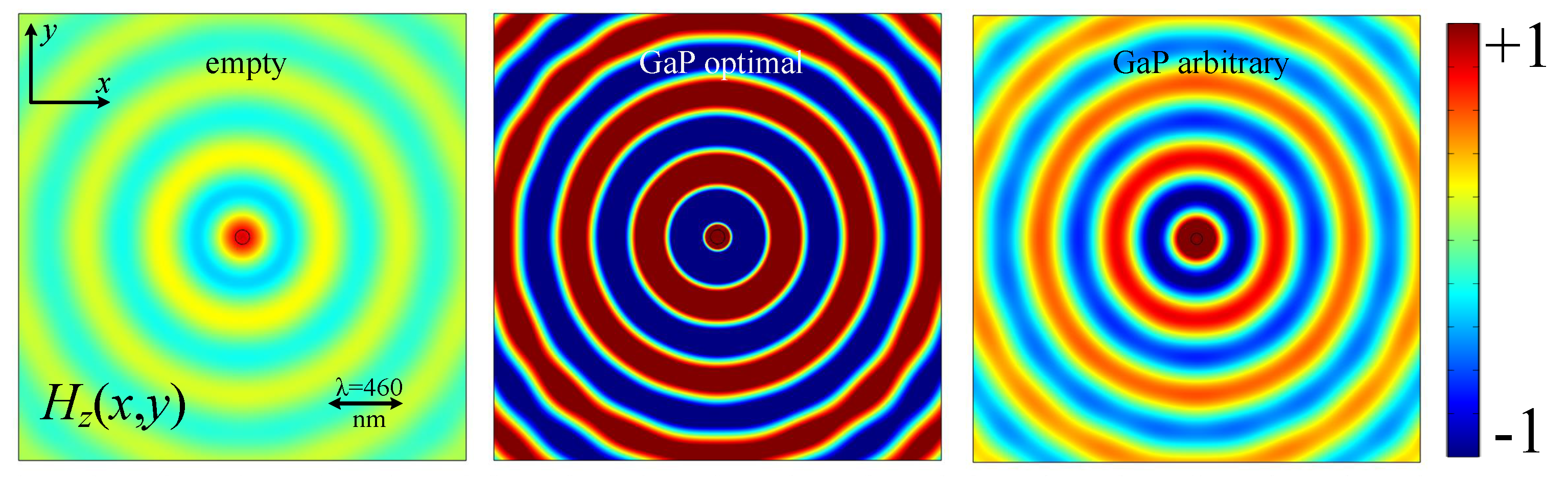
In
Figure 5, we consider the same cases as in
Figure 4, but for the optimal GaP cover at TE excitation (maximum of the respective curve of
Figure 3b). Again, we note a considerable enhancement of the produced magnetic field
between the left and the middle panel where the best-performing design was employed. On the contrary, if we changed the dimensions
of the cylindrical shell (right panel), the radiation diminished compared to the optimal scenario, but remained strong.
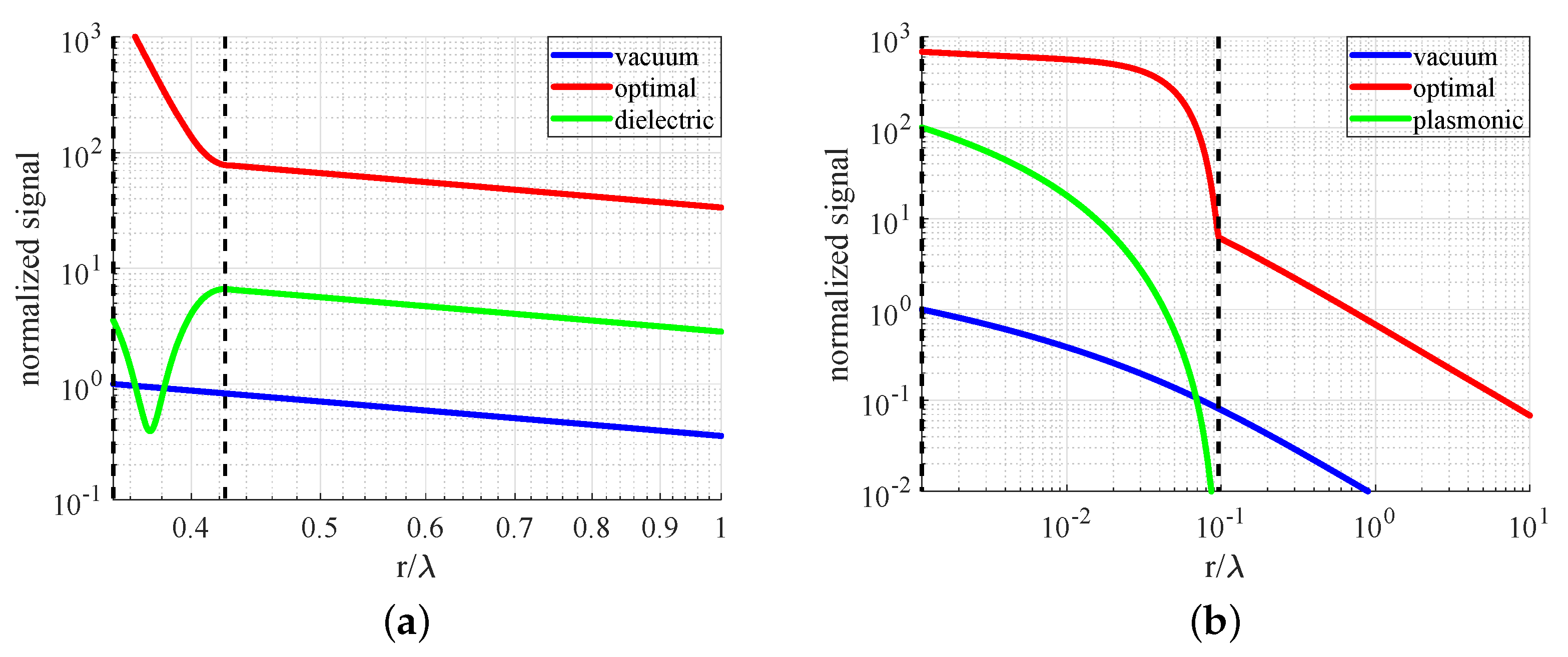
The efficiency of the optimal shells is indicated in
Figure 6, where the squared magnitude of the field (
for TM or
for TE waves), expressed in arbitrary units, is represented as a function of the electrical radial distance
. In
Figure 6a, we consider the TM cylindrical shell of
Figure 4 being filled with: (i) the optimal medium (silver,
), (ii) a hypothetical dielectric having the opposite real part of relative permittivity (
), and (iii) air (
). We notice that the plasmonic coat created a pair of evanescent modes in it (boundaries indicated with vertical dashed lines), which admitted the signal taking substantial values and inevitably inflating the radiative power. On the contrary, when the dielectric counterpart was used, the field became locally minimized in the cladding, and the radiation became only moderately amplified compared to the case of an absent shell. In
Figure 6b, we repeat the calculations of
Figure 6a for the TE cylindrical shell of
Figure 5. It is clear that the substantial reflections back to the source (which were expressed via the large values of the signal into the optimal GaP cladding) were the necessary price to be paid in order for the radiation to be enhanced. Note finally that when the plasmonic counterpart (opposite real part of permittivity) was employed, the source was practically isolated from the outer space, and the vast portion of the provided energy was converted into the thermal form within the shell.
In
Figure 7, we examine again the two selected designs and test their response if the radii
are not properly picked. In
Figure 7a, where the silver shell is regarded, we notice that the relative radiation
dramatically drops if the radii ratio
or the external size
changes slightly, unless they are both modified inversely proportionally to each other. In fact, the operation point (marked by ×) lied along an extremely elongated parametric region resembling a line of decreasing
for increasing
. In
Figure 7b, we consider the GaP cladding for TE waves, and it is apparent that the robustness of that design was much higher than the one of
Figure 7a. It is natural to deduce the conclusion that the response was also insensitive with respect to the position of the line source, namely if the dipole was not exactly centralized along the axis of the cylindrical shell. It should be also mentioned that the optimal solution for the GaP case yielded
, which means that the air gap between the line source and the internal surface was practically absent, namely the dipole should be embedded in the solid dielectric cylinder.
It should be stressed that the quantities defined in (1) and (2) and represented in
Figure 3,
Figure 4 and
Figure 5, as well as in
Table 1 are not the radiation efficiencies [
21] if the line source is considered as antenna. It is well-known that radiation efficiency
is defined as the ratio of the same scattered power
as in (1) and (2), not divided by the incident power
in the absence of the structure, but by the actual input power
, which takes into account the effect of the cylindrical shell. More specifically,
only if
(vacuum), and unlike the ratio
,
is always bounded by unity:
. In the considered configuration of
Figure 2c, our intention is not to maximize the radiation efficiency
since the structure does not resemble an antenna, where directivity (at least across one plane) is usually a prerequisite for efficient operation. On the contrary, through this omni-directional pattern, which remained unaltered along the
z axis, we aimed at proposing structures absorbing as fast as possible the available energy from the source (maximal power
) and sending it far away to support effective wireless power transfer [
22].
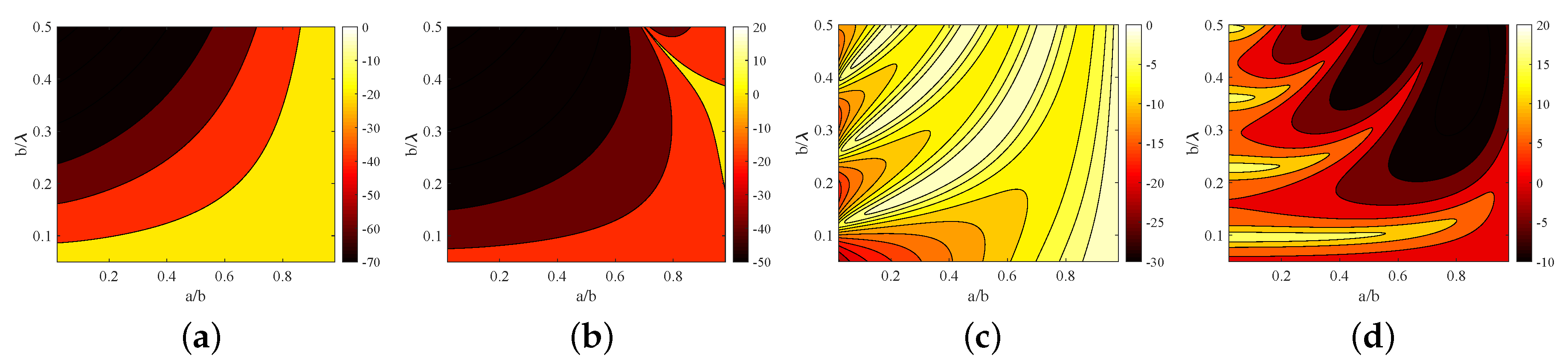
However, to demonstrate the difference between the two metrics (
vs.
), we show their variation on the design parametric space
in
Figure 8. In particular, we examined silver (
Figure 8a,b) and GaP (
Figure 8c,d) shells, and we computed both
(
Figure 8b,d across a larger map than that of
Figure 7a,b) and
(
Figure 8a,b) over the entire ranges of aspect ratios
and optical size
. It is clear that designs giving substantial
do not necessarily imply large radiation efficiencies. Furthermore, it is obvious that the same approach can be adopted if maximization of
is the objective; however, the parametric combinations yielding high
structures were more extended than the ones serving the purpose of high relative radiation. In this sense, and at least for the two employed media (Ag, GaP), optimizing
is a more challenging task than maximizing the radiation efficiency of a filamentary antenna. Therefore, we confined our research to the detection of devices exhibiting maximal radiation power
, launching the fastest the energy taken from the photonic “battery” into the far region.
In
Figure 9a, we consider the frequency response of the silver-based optimized design (
Figure 4) across the entire visible spectrum
for both polarizations (not only for TM waves). We notice that the performance dropped rapidly away from the optimal wavelength
, which is obvious from
Figure 7a, where the sensitivity of the design is demonstrated. It is also remarkable that the same structure that has been optimized for TM excitation gave a substantial score for TE fields at a much smaller wavelength. Indeed, the optimal TE designs should be electrically more sizeable than the corresponding TM ones since in the latter case, the electric field oscillated along the infinite dimension of the regarded cylinder, and thus, a device of smaller radius can be more responsive [
9]. In
Figure 9b, we obtain a similar graph to that of
Figure 9a, but for the GaP-based design of
Figure 5 working at
. We can easily observe the wideband effect of the proposed device (which is also indicated in
Figure 7b) and the poor performance of the cylindrical shell for the excitation that it has not been optimized (TM).


