Article

A Modified Design of a Hexagonal Circular Photonic Crystal Fiber with Large Negative Dispersion Properties and Ultrahigh Birefringence for Optical Broadband Communication

by
Shovasis Kumar Biswas
1,*,
Rishad Arfin
2,
Ashfia Binte Habib
2,
Syed Bin Amir
2,
Zunayeed Bin Zahir
2,
Mohammad Rezaul Islam
2 and
Md. Shahriar Hussain
2
1
Department of Electrical and Electronic Engineering, Independent University Bangladesh, Dhaka 1229, Bangladesh
2
Department of Electrical and Computer Engineering, North South University, Dhaka 1229, Bangladesh
*
Author to whom correspondence should be addressed.
Photonics 2019, 6(1), 19; https://doi.org/10.3390/photonics6010019
Submission received: 24 January 2019 / Revised: 17 February 2019 / Accepted: 21 February 2019 / Published: 25 February 2019
(This article belongs to the Special Issue Lightwave Communications and Optical Networks)

Abstract

:
In this paper, we propose a modified design of a hexagonal circular photonic crystal fiber (HC-PCF) which obtains a large negative dispersion and ultrahigh birefringence simultaneously. The optical properties of the proposed HC-PCF were investigated using the finite element method (FEM) incorporated with a circular perfectly matched layer at the boundary. The simulation results showed large negative dispersion of −1044 ps/nm.km and ultrahigh birefringence of 4.321 × 10⁻² at the operating wavelength of 1550 nm for the optimum geometrical parameters. Our proposed HC-PCF exhibited the desirable optical properties without non-circular air holes in the core and cladding region which facilitates the fabrication process. The large negative dispersion of the proposed microstructure over the wide spectral range, i.e., 1350 nm to 1600 nm, and high birefringence make it a suitable candidate for high-speed optical broadband communication and different sensing applications.

1. Introduction

Photonic crystal fiber (PCF) [1] is a new class of optical waveguide that guides the electromagnetic field by a periodic arrangement of dielectric medium that goes down the entire length of the fiber. In general, a PCF microstructure involves lattice of air holes which appear on a background material, usually, silica. Fundamentally, the confinement and propagation of the light takes place in the fiber core due to the existence of the periodic low-index air hole. The physical mechanism for which the light guidance takes place in the optical waveguide due to the difference in the refractive index is known as total internal reflection (TIR) or index guiding [2].
Photonic crystal fibers, in recent years, have drawn significant attention as these microstructures exploit extraordinary optical properties which are unlikely to be achieved by the conventional optical fibers. Photonic fibers are being employed in many optical devices such as telecommunication sensors [3], polarization sensitive devices [4], wavelength de-multiplexer [5], sensors [6], filters [7], and splitters [8].
The fundamental drawback of high-bit-rate conventional optical transmission systems is the broadening of optical pulses due to group velocity. The spreading of the optical pulses needs to be compensated for long-distance transmission. Therefore, dispersion compensating fibers (DCFs) which show negative dispersion characteristics are widely employed to mitigate the broadening effect [9]. The negative dispersion properties should be distributed throughout the broad spectral range in order to compensate the accumulated dispersion in the conventional optical fibers. However, it is difficult to obtain large negative dispersion by using conventional DCFs for broadband application. Moreover, single mode operation in DCFs needs to be ensured in order to avoid signal degradation. On the other hand, PCFs ensure single mode operation and allow flexibility in tuning dispersion properties [10]. Several designs have been proposed to obtain large negative dispersion coefficients over a wideband. For example, a design of an octagonal PCF with six air hole rings is proposed in Reference [11] that obtains a negative dispersion of 239.5 ps/nm.km at 1550 nm. Selim habib et al. proposed a design based on holey fibers in [12] which exhibits negative dispersion coefficient of 470 to 850 ps/nm.km over S to L-bands. Furthermore, a design of a spiral microstructure fiber is proposed in Reference [13] that obtains 327 ps/nm.km at 1550 nm. Mejbaul Haque et al. [14] proposed a single mode circular PCF design which demonstrates a negative dispersion of 790.12 ps/nm.km at 1550 nm wavelength.
It is possible to obtain novel optical properties such as high birefringence, non-linearity, and low confinement loss with different geometrical designs of PCF. Different sizes and shapes (e.g., square, elliptical, circular) [15,16] of the air holes near the asymmetric core region [17] result in birefringence at different levels which can be employed in different sensing applications. By exploiting high birefringence, PCF refrains cross coupling of the optical power between two polarization modes and can be employed as polarization maintaining fiber (PMF) [18]. Different designs of PCF have been proposed to obtain high birefringence characteristics. For instance, a novel PCF with rectangular air holes in the core region is proposed by Wang et al. in Reference [19] that obtains a birefringence of 1.83 × 10 2 at 1550 nm. Rashid et al. [20] designed a dodecagonal shaped five-ring PCF which has reported a birefringence of 2.05 × 10 2 . A spiral PCF was developed in Reference [21] which obtains a birefringence of 1.16 × 10 2 . Moreover, Agarwal et al. [22] showed a PCF which achieved a high birefringence of 2.2 × 10 2 at 1550 nm with non-circular air holes arranged in a golden spiral pattern. Furthermore, Chen et al. [23] proposed a design of a hexagonal PCF with non-circular core and circular cladding which attains a birefringence of 1.5 × 10 2 . However, different geometrical shapes of the air hole, usually non-circular, around the solid core lead to difficulties in the fabrication process. The fabrication process becomes much easier by using a drilling method [24] or stack and draw technique [25] when the design of the PCF is limited to circular air holes. Recently, a design of a hexagonal PCF with all circular air holes was proposed in Reference [26] which was able to achieve a high birefringence of 3.87 × 10 2 at the excitation wavelength of 1550 nm.
In this work, we propose a modified design of hexagonal circular photonic crystal fiber (HC-PCF) of five air hole rings. We only used circular air holes in the design of the photonic structure which makes the fabrication easier. The proposed structure consists of an asymmetric core region where one air hole is missing from the first ring and the opposite one with a reduced diameter. The diameter of the horizontally located circular air holes in the second ring is reduced which results in mirror-symmetry refractive index profile in the design. The simulation results show that the proposed structure exhibits a large negative dispersion over a wideband and 1044 ps/nm.km at an operating wavelength of 1550 nm. Furthermore, the proposed HC-PCF has a birefringence of 4.321 × 10 2 at the operating wavelength which is till now the highest achievable birefringence using all circular air holes in the fiber structure. The exploitation of large negative dispersion and ultrahigh birefringence of our proposed HC-PCF structure makes it a potential candidate for high-bit-rate optical broadband communication and various sensing applications.

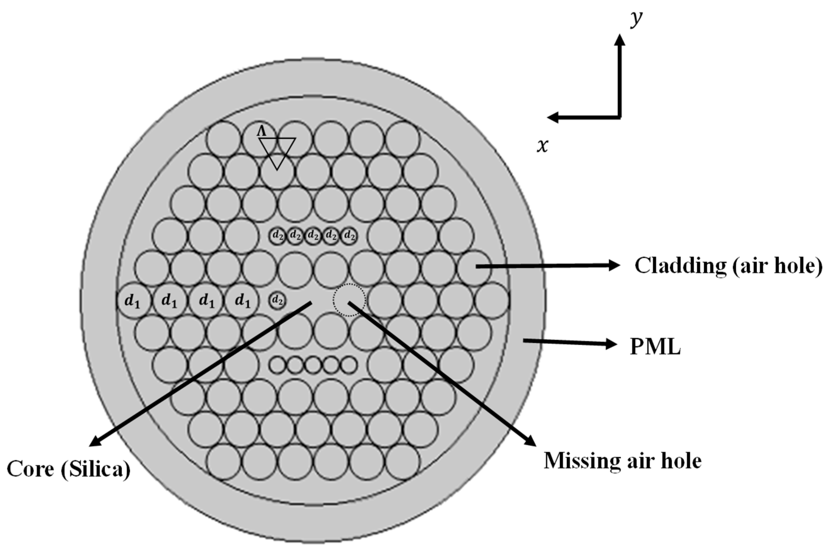
2. Design Structure of the Proposed HC-PCF
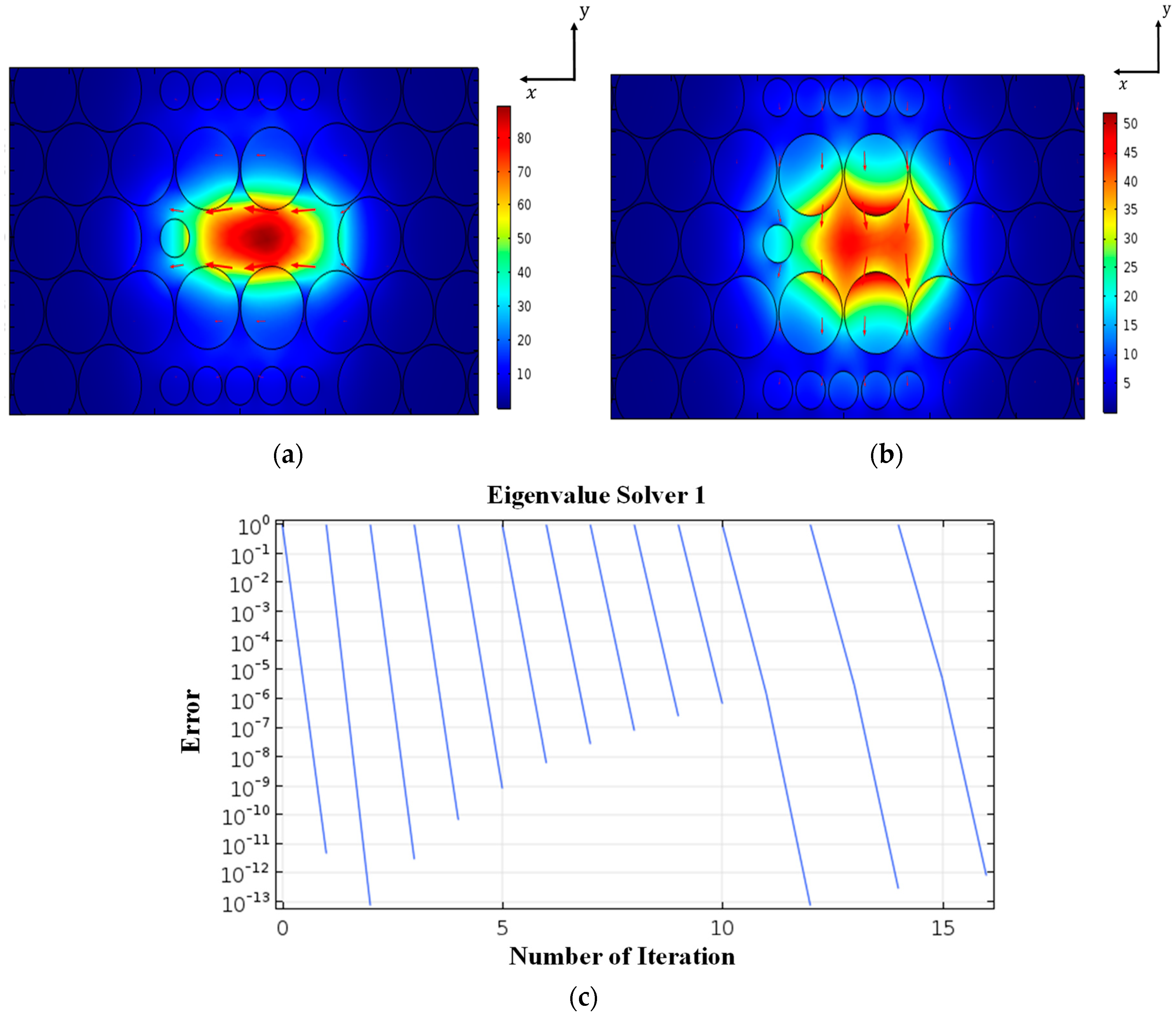
Figure 1 depicts the distribution of the air holes on the cross-section of the proposed single mode HC-PCF. The design structure contains only circular air holes since it makes fabrication process more feasible. The PCF structure has a distribution of five air hole rings on a single material, i.e., silica. The air hole at the center is missing which makes the inner core of the proposed structure. The first ring consists of five circular air holes where one air hole is reduced in diameter d 2 and the opposite air hole along the same axis is missing (shown in dotted lines). Therefore, the unequal diameters, i.e., d 1 > d 2 , and asymmetric distribution of the circular air holes at the inner core makes it possible to obtain high birefringence. The second ring consists of sixteen circular air holes of unequal diameters, i.e., d 1 > d 2 , as well. The reduced diameter d 2 air holes located in the second ring results in an increase of the local refractive index which makes a portion of the ring act as an outer core. The cladding area, i.e., from ring three to five, contains the periodic distribution of the air holes of the same diameter d 1 . The spatial distance between the centers of the two adjacent holes is called pitch and denoted as Λ. Our proposed HC-PCF has a total number of three geometrical parameters, i.e., d 1 , d 2 , and Λ which can be chosen as degrees of freedom. Therefore, by performing parametric studies on the geometrical design parameters, it is possible to obtain promising optical modal properties, e.g., dispersion, birefringence, and non-linearity of the proposed HC-PCF for particular frequency regime and application. The variation in the optical characteristics of the proposed HC-PCF due to the lenient precision in the fabrication process was also investigated.

3. Numerical Method

Numerical simulation was carried out in order to investigate the guiding properties of the modified HC-PCF. Since the proposed PCF is a microstructure-design, finite element method (FEM) was employed to carry out the electromagnetic investigation, i.e., field distribution and effective mode indices. Commercially available, FEM-based software package COMSOL Multiphysics, version 5.3, was used. A circular perfectly matched layer (PML), with a thickness of 10 % of the cladding radius, was applied at the boundary of the design to avoid reflection and back scattering. The thickness of the uniformly employed PML around the proposed HC-PCF was 1 μm with a scaling factor of 1. Finer mesh was applied to the entire structure. By solving Maxwell’s equations in the microstructure design, FEM derives the propagation constant β through mode analysis. The refractive index n ( λ ) of the background material, i.e., silica, is a function of wavelength and can be estimated using the Sellmeier equation [27] as follows:
n ( λ ) = ( 1 + i = 1 N B i λ 2 λ 2 C i ) 1 2 ,
where n ( λ ) is the wavelength-dependent refractive index of the material, λ is the wavelength in μm, and B i and C i are sellmeier coefficients for the material which can be determined experimentally. Usually, for glass material N equals 3. Once the propagation constant β is obtained, the effective refractive index n e f f can be estimated from the following expression [28]:
n e f f = β ( λ ,   n ( λ ) ) k 0 ,
where k 0 equals 2 π λ is the wave number of free space and n e f f is the effective refractive index. The effective refractive index n e f f is not only wavelength-dependent but also depends on the mode. Therefore, it is called modal index as well. Since the guiding properties such as dispersion, modal birefringence, numerical aperture, non-linearity, and confinement loss of the PCF are investigated, the formulations for the corresponding optical parameters are discussed in this section. Chromatic dispersion D ( λ ) of the PCF is wavelength-dependent and can be estimated from the effective refractive index n e f f of the fundamental mode using the following expression [28]:
D ( λ ) = λ c   d 2 R e [ n e f f ] d λ 2 ,
where the unit of the dispersion in ps/(nm.km), λ is the wavelength in μm, c is the velocity of light in vacuum, and R e [ n e f f ] is the real part of the modal refractive index n e f f . Chromatic dispersion of the PCF can be manipulated by changing the geometrical parameters, e.g., pitch Λ , diameter d , and distribution of the air holes in the PCF structure. The modal birefringence B depends on the polarization-dependent effective refractive indices and is calculated by the following equation [28]:
B = | n e f f ,   x n e f f , y | ,
where n e f f , x and n e f f , y are effective refractive indices of two orthogonal polarization modes: x polarization and y polarization, respectively. However, the non-linearity of the PCF largely depends on the optical parameters of the core, i.e., effective mode area A e f f . The effective area A e f f of the core is defined as follows [28]:
A e f f = ( | E | 2 d x d y ) 2 | E | 4 d x d y ,
where the unit of the mode effective area is μm2 and E is the electric field. The non-linearity γ is inversely proportional to the effective mode area A e f f [28] and can be defined as follows:
γ = 2 π λ × n 2 A e f f ,
where the unit of non-linearity is W 1 k m 1 and n 2 is the Kerr constant of the material with a unit of m 2 W .
In PCF, the optical power is mostly confined in the core area due to the higher refractive index in contrast to the cladding, i.e., surrounding air holes. However, since there is a finite number of air holes around the core, the portion of the optical energy penetrates inevitably into the cladding area and results in confinement loss or leakage loss. The confinement loss L c can be estimated by the following expression [29]:
L c = 8.686 × k 0 I m   [ n e f f ] × 10 3 ,
where the unit of the confinement loss is dB/km and I m   [ n e f f ] is the imaginary part of the effective refractive index n e f f .
The amount of optical power collection in PCF is quantified by numerical aperture N A , a dimensionless parameter. The expression for numerical aperture N A can be given by as follows [30]:
N A = [ 1 + π A e f f λ 2 ] 1 2

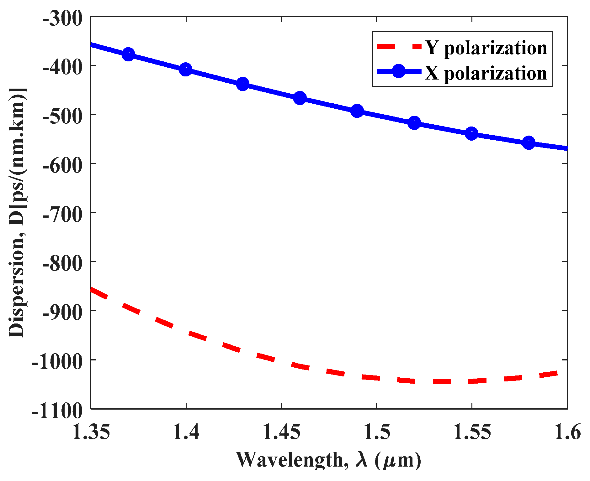
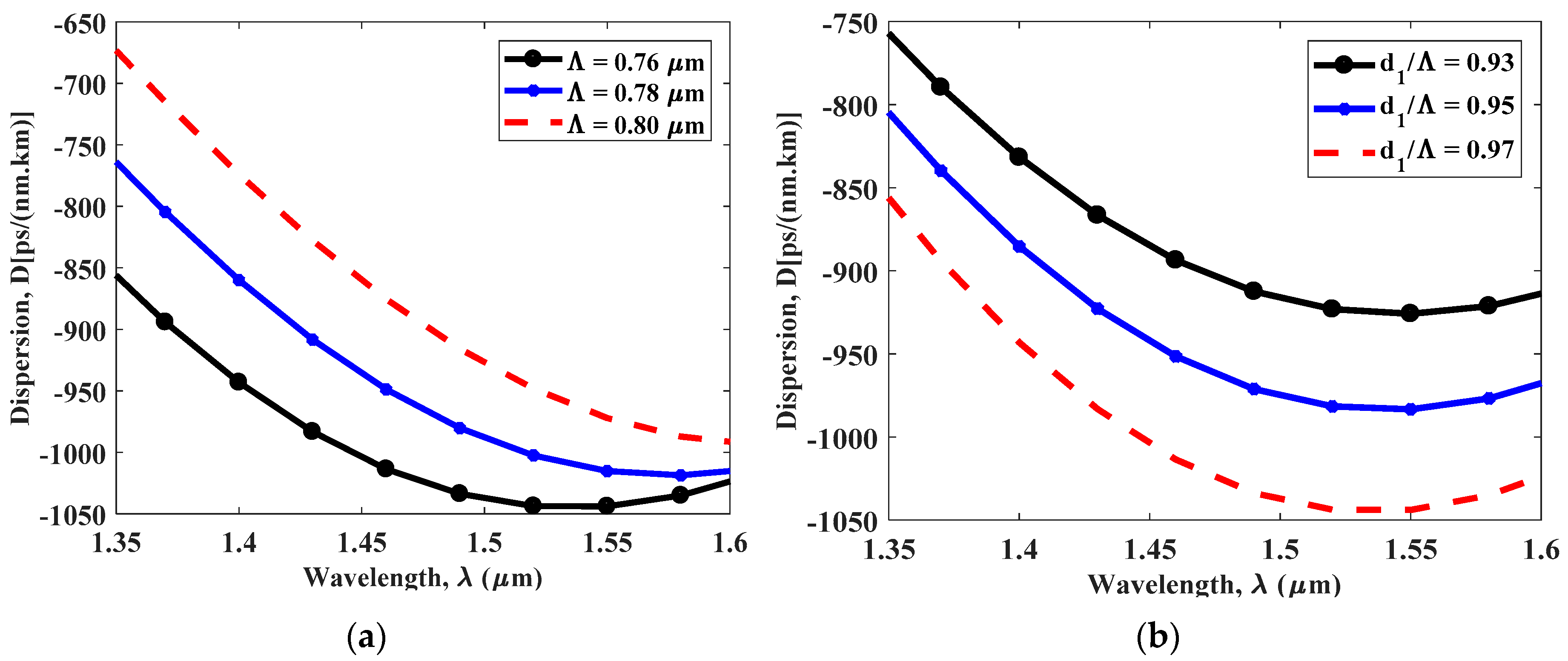
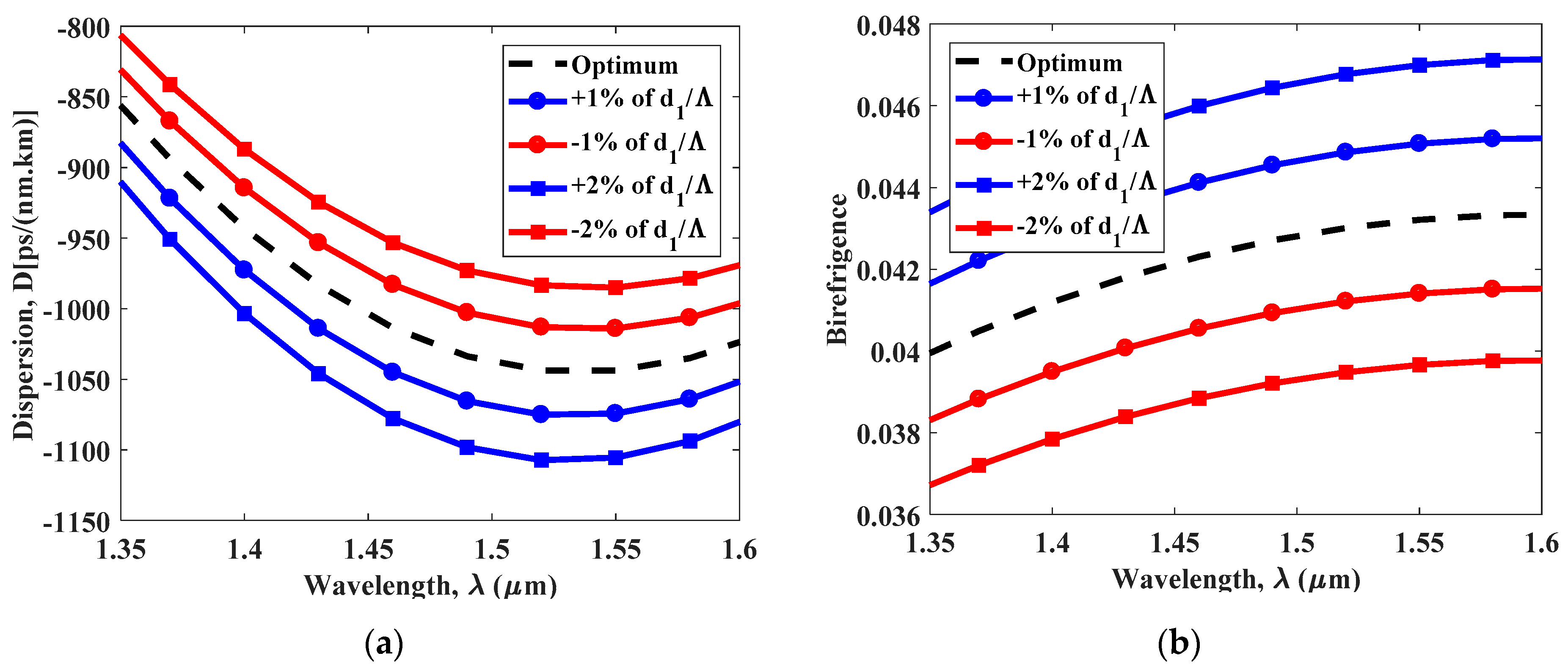
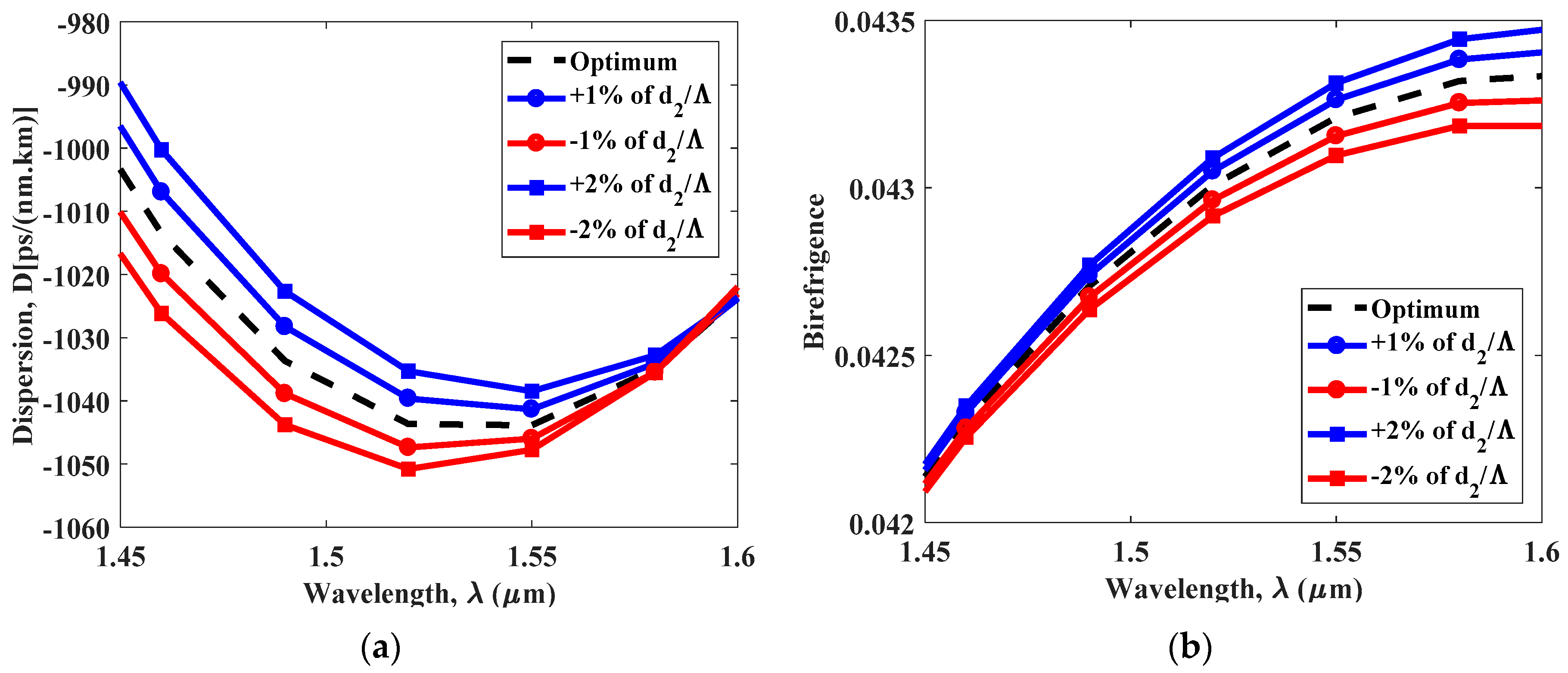
4. Simulation Result and Discussion

In this section, the guiding properties such as dispersion, birefringence, non-linearity, and numerical aperture of the proposed HC-PCF are investigated by changing the geometrical parameters of the microstructure. Figure 2a,b show the field distribution of the fundamental mode of the proposed HC-PCF for both x and y polarization at wavelength of 1550 nm respectively. The simulation results demonstrate that the electric field is strongly confined in the asymmetric core region of the HC-PCF for two orthogonal polarizations. The convergence of the simulated results is also investigated in order to determine the accuracy of the approximated solution. Figure 2c shows that the error meets an acceptable error tolerance of 10 6 after every iteration and finally reaches to 10 12 at 16th iteration.
Figure 3 shows the chromatic dispersion properties of the proposed HC-PCF as a function of wavelength for the optimized geometrical parameters. The result shows that the dispersion values for y polarization mode are much more promising than x polarization over a broad spectral range of 1350 nm to 1600 nm. The dispersion coefficient is obtained around 1044 ps/nm.km at 1550 nm for y polarization for the optimum parameters.
We have investigated the effect on the dispersion coefficient due to changes in the geometrical parameters, i.e., Λ , d 1 , and d 2 . Figure 4a shows the changes in the wavelength-dependent dispersion coefficient from 1350 nm to 1600 nm for different values of Λ with fixed d 1 and d 2 . The dispersion coefficient has been estimated 1044 ps/nm.km, 1015 ps/nm.km, and 972.10 ps/nm.km when the pitch is changed to 0.76 μ m , 0.78 μ m , and 0.80 μ m , respectively for 1550 nm. This is due to fact that as the pitch Λ increases (with fixed d 1 and d 2 ) the optical field in the core region for the fundamental mode is no longer strongly confined which apparently changes the dispersion coefficient D ( λ ) .
The effect of the change in the diameter d 1 on the dispersion properties of the proposed HC-PCF has been investigated. Figure 4b shows that with a fixed Λ and d 2 , the calculated dispersion is respectively 1044 ps/nm.km, 983.3 ps/nm.km, and 925.8 ps/nm.km when d 1 / Λ is changed to 0.97, 0.95, and 0.93 at λ = 1550 nm. This is due to fact that, as d 1 increases with a fixed Λ, the local average refractive index around the core region decreases. Therefore, the confinement of the optical energy in the core region becomes strong which results in high negative dispersion at operating wavelength of 1550 nm. The dispersion properties have been further investigated with the variation of d 2 of the proposed HC-PCF in Figure 4c. It shows that with a fixed Λ and d 1 , the dispersion of the proposed HC-PCF at 1550 nm is about 1044 ps/nm.km, 1050 ps/nm.km, and 1042 ps/nm.km when d 2 / Λ equals 0.45 ,   0.43 , and 0.40 , respectively. The simulation result shows that the change in d 2 causes a small change in dispersion coefficient at the excitation wavelength of 1550 nm.
The birefringence characteristics of the proposed PCF have also been investigated. Figure 5a reports the changes in the modal birefringence of the proposed HC-PCF as a function of wavelength for different values of the pitch Λ with fixed d 1 and d 2 . The difference between the effective refractive index of two polarization modes can be increased by introducing spatial asymmetry in the index profile near the core area. Figure 5a shows that the modal birefringence of the PCF structure increases as function of wavelength from 1350 nm to 1600 nm. The birefringence of the HC-PCF is estimated to be 4.321 × 10 2 , 4.292 × 10 2 , and 4.249 × 10 2 when the pitch Λ is changed to 0.76 μm, 0.78 μm, and 0.80 μm, respectively at 1550 nm. Figure 5b,c represent the effect of the d 1 and d 2 on the birefringence characteristics of PCF, respectively. Figure 5b shows significant changes in the modal birefringence over the broad spectral range from 1350 nm to 1600 nm due to the variation in d 1 . The simulation result clearly shows that with an increase in d 1 , the birefringence strongly increases as a function of wavelength for fixed Λ and d 2 . This is due to the fact that larger d 1 with fixed d 2 results in strong asymmetry in the refractive index profile. The birefringence estimated for the PCF structure are 3.613 × 10 2 , 3.95 × 10 2 , and 4.321 × 10 2 when d 1 / Λ is changed to 0.93, 0.95, and 0.97, respectively at 1550 nm. However, Figure 5c illustrates that the effect of the change in d 2 on the modal birefringence is pronounced at longer wavelengths from 1500 nm to 1600 nm.
The optical non-linearity of the proposed structure has also been studied by changing the geometrical parameters. Figure 6a shows the non-linearity of the proposed HC-PCF for two orthogonal x and y polarizations. The non-linear characteristic of the proposed microstructure was strongly pronounced at higher frequencies. The optimum result for the non-linearity was obtained for x polarization and was 77.85 W 1 km 1 . Figure 6b shows the variation in the non-linearity of the PCF with fixed diameters and changes in the pitch Λ . However, insignificant change in the non-linearity was observed over the wideband due to the change in the pitch. Figure 6c,d shows the effect of changing the diameters d 1 and d 2 on the non-linear properties of the proposed HC-PCF. As d 1 increased with rest of the design parameters were kept fixed, the light confined strongly in the core region and exhibited high non-linearity. The measured non-linearity for the PCF were 77.85   W 1 km 1 , 76.46   W 1 km 1 , and 74.97   W 1 km 1 when d 1 / Λ was changed to 0.97, 0.95, and 0.93, respectively at 1550 nm. Figure 6d also reported an enhancement in the non-linear properties of the proposed HC-PCF as d 2 increased. This is due to fact that as d 2 increases the effective area for the fundamental mode confined in the core decreases which results in high nonlinearity.
Figure 7a represents the numerical aperture of the proposed HC-PCF as function of wavelength. The highest numerical aperture is obtained for x polarization mode for the optimized geometrical parameters is about 0.5607 at λ = 1550 nm. However, the value of the numerical aperture for both polarization modes enhances proportionally with the wavelength. We also studied the confinement or leakage loss as a function of wavelength for the optimized design parameters. The confinement loss is calculated and found to be in order of 10 2 dB/cm at the operating wavelength of 1550 nm, as shown in Figure 7b. However, the confinement loss can be reduced significantly by increasing the number of air hole rings in the structure. Figure 8a,b show the wavelength dependence dispersion properties and birefringence of the proposed structure for variation in the pitch from ± 1 % to ± 2 % . It is to be noted that for the broad spectral range from 1350 nm to 1600 nm, the chromatic dispersion for the proposed design gradually decreases, i.e., gets more negative, and birefringence increases with the increase in the wavelength. However, the change in both dispersion and birefringence due to the variation in the pitch becomes less significant at longer wavelength from 1550 nm to 1600 nm.
Furthermore, we have studied the changes in the dispersion characteristics and birefringence of the proposed structure for the variation in d 1 / Λ from ± 1 % to ± 2 % . Figure 9a,b show that the change in both dispersion and birefringence characteristics due to the variation in d 1 is relatively more pronounced than the variation of the pitch Λ at longer wavelength.
Finally, we have performed study on the effect on the dispersion and birefringence of the proposed HC-PCF due to the variation in d 2 / Λ . Figure 10a,b illustrate that both the optical properties of the photonics structure changes as function of wavelength. As the wavelength increases the dispersion coefficient becomes more negative and birefringence of the proposed structure enhances gradually and very much distinguishable over the wide band. However, the result indicates that change in d 2 leads to smaller variation in the dispersion coefficient and birefringence compared to change in d 1 .
The modal properties of the proposed modified HC-PCF were compared with the contemporary PCF designs in Table 1. The comparisons are discussed in terms of chromatic dispersion and birefringence at the operating wavelength of 1550 nm for different shapes of the air hole in the PCF structure. Table 1 shows that the highest dispersion coefficient was achieved in Reference [31] which involves both circular and elliptical air holes in the PCF structure and makes the fabrication process challenging. Our modified HC-PCF only involves circular air holes and shows highest dispersion coefficient at 1550 nm among all the circular PCF designs. It is also clearly evident from the table that the proposed HC-PCF achieves the highest birefringence among all circular and non-circular PCF designs. One of the primary goals of our design is to ensure the feasibility of the fabrication process. There are few techniques which can be employed to fabricate PCF design such as conventional drilling, stack and draw method [25,32], and sol-gel casting [33]. The shape of the core along with the refractive index profile of the cladding can easily be controlled using stack and draw method [32]. Sol-gel casting allows a broad range of design flexibility which can be employed to fabricate PCF at a large scale. Fabrication of several complex structures of PCFs using straw and draw methods and sol-gel techniques have been reported in References [33,34]. Since our proposed design only involves circular air holes in the core and cladding region, both of these fabrication techniques can be used to manufacture the proposed PCF structure which will be comparatively easier than the PCFs which contain non-circular air holes.

5. Conclusions

In this paper, design of a single-mode hexagonal PCF structure was presented. The microstructure was able to obtain both a large negative dispersion coefficient and a high birefringence at the excitation wavelength of 1550 nm. Numerical studies illustrate that a negative dispersion of 1044 ps/nm.km was achieved with the optimum geometrical parameters. Moreover, it was also possible to attain a high birefringence of 4.321 × 10 2 . Parametric studies on the optical properties such as chromatic dispersion, birefringence, non-linearity, and numerical aperture of the proposed HC-PCF were also carried out with the variation in the geometrical design parameters. Finally, the deviation in the guiding properties were analyzed due to the imprecision in the fabrication process. This modified PCF design with large negative dispersion coefficient and ultrahigh birefringence can be a potential candidate for high-bit-rate long distance optical transmission and optical fiber sensing.

Author Contributions

S.K.B. and R.A. designed the model and performed the numerical simulations. A.B.H., Z.B.Z, and S.B.A. performed the calculations and MATLAB simulations. R.A. and S.K.B. wrote the manuscript with input from all authors. R.A., S.K.B., and M.S.H. proposed the core idea, and were in change of overall direction and planning when performing the numerical simulations. All authors discussed the results and contributed to the final manuscript.

Funding

This research received no external funding.

Acknowledgments

The author acknowledges financial support from the Independent University, Bangladesh.

Conflicts of Interest

The authors declare that there are no conflicts of interest regarding the publication of this paper.

References

  1. Broeng, J.; Mogilevstev, D.; Barkou, S.E.; Bjarklev, A. Photonic Crystal Fibers: A New Class of Optical Waveguides. Opt. Fiber Technol. 1999, 5, 305–330. [Google Scholar] [CrossRef]
  2. Zheltikov, A.M. Holey fibers. Physics-Uspekhi 2000, 43, 1125–1136. [Google Scholar] [CrossRef]
  3. Knight, J.C. Photonic crystal fibres. Nature 2003, 424, 847–851. [Google Scholar] [CrossRef] [PubMed]
  4. Kubota, H.; Kawanishi, S.; Koyanagi, S.; Tanaka, M.; Yamaguchi, S. Absolutely Single Polarization Photonic Crystal Fiber. IEEE Photonics Technol. Lett. 2004, 16, 182–184. [Google Scholar] [CrossRef]
  5. Dadabayev, R.; Shabairou, N.; Zalevsky, Z.; Malka, D. A visible light RGB wavelength demultiplexer based on silicon-nitride multicore PCF. Opt. Laser Technol. 2019, 111, 411–416. [Google Scholar] [CrossRef]
  6. Medhat, M.; El-Zaiat, S.Y. Interferometric determination of the birefringence dispersion of anisotropic materials. Opt. Commun. 1997, 141, 145–149. [Google Scholar] [CrossRef]
  7. Varshney, S.K.; Saitoh, K.; Saitoh, N.; Tsuchida, Y.; Koshiba, M.; Sinha, R.K. Strategies for realizing photonic crystal fiber bandpass filters. Opt. Express 2008, 16, 9459–9467. [Google Scholar] [CrossRef] [PubMed]
  8. Florous, N.; Saitoh, K.; Koshiba, M. A novel approach for designing photonic crystal fiber splitters with polarization-independent propagation characteristics. Opt. Express 2005, 13, 7365–7373. [Google Scholar] [CrossRef] [PubMed]
  9. Grüner-nielsen, L.; Wandel, M.; Kristensen, P.; Jørgensen, C.; Jørgensen, L.V.; Edvold, B.; Pálsdóttir, B.; Jakobsen, D. Dispersion-Compensating Fibers. J. Lightw. Technol. 2005, 23, 3566–3579. [Google Scholar] [CrossRef]
  10. Saitoh, K.; Koshiba, M.; Hasegawa, T.; Sasaoka, E. Chromatic dispersion control in photonic crystal fibers: Application to ultra-flattened dispersion. Opt. Express 2003, 11, 843. [Google Scholar] [CrossRef] [PubMed]
  11. Kaijage, S.F.; Namihira, Y.; Hai, N.H.; Begum, F.; Razzak, S.M.A.; Kinjo, T.; Miyagi, K.; Zou, N. Broadband dispersion compensating octagonal photonic crystal fiber for optical communication applications. Jpn. J. Appl. Phys. 2009, 48, 0524011–0524018. [Google Scholar] [CrossRef]
  12. Selim Habib, M.; Mejbaul Haque, M.; Samiul Habib, M.; Hasan, M.I.; Shaifur Rahman, M.; Razzak, S.M.A. Polarization maintaining holey fibers for residual dispersion compensation over S + C + L wavelength bands. Optik (Stuttg.) 2014, 125, 911–915. [Google Scholar] [CrossRef]
  13. Samiul Habib, M.; Nasim, K.M.; Selim Habib, M.; Imran Hasan, M.; Ahmad, R. Relative dispersion slope matched dispersion compensating highly birefringent spiral microstructure optical fibers using defected core. Opt. Eng. 2013, 52, 096110. [Google Scholar] [CrossRef]
  14. Mejbaul Haque, M.; Shaifur Rahman, M.; Samiul Habib, M.; Razzak, S.M.A. Design and characterization of single mode circular photonic crystal fiber for broadband dispersion compensation. Optik (Stuttg.) 2014, 125, 2608–2611. [Google Scholar] [CrossRef]
  15. Yue, Y.; Kai, G.; Wang, Z.; Sun, T.; Jin, L.; Lu, Y.; Zhang, C.; Liu, J.; Li, Y.; Liu, Y.; et al. Highly birefringent elliptical-hole photonic crystal fiber with squeezed hexagonal lattice. Opt. Lett. 2007, 32, 469–471. [Google Scholar] [CrossRef]
  16. Steel, M.J.; Osgood, R.M. Elliptical-hole photonic crystal fibers. Opt. Lett. 2001, 26, 229. [Google Scholar] [CrossRef] [PubMed]
  17. Blanch, A.O.; Knight, J.C.; Wadsworth, W.J.; Arriaga, J.; Mangan, B.J.; Birks, T.A.; Russell, P.S.J. Highly birefringent photonic crystal fibers. Opt. Lett. 2000, 25, 1325–1327. [Google Scholar] [CrossRef]
  18. Chaudhuri, P.R.; Paulose, V.; Zhao, C.; Lu, C. Near-elliptic core polarization-maintaining photonic crystal fiber: Modeling birefringence characteristics and realization. IEEE Photonics Technol. Lett. 2004, 16, 1301–1303. [Google Scholar] [CrossRef]
  19. Wang, W.; Yang, B.; Song, H.; Fan, Y. Investigation of high birefringence and negative dispersion photonic crystal fiber with hybrid crystal lattice. Optik (Stuttg.) 2013, 124, 2901–2903. [Google Scholar] [CrossRef]
  20. Rashid, M.M.; Anower, M.S.; Hasan, M.R.; Tabassum, N. Hexagonal shaped core dodecagonal PCF with high birefringence and nonlinear coefficient. In Proceedings of the 2017 International Conference on Electrical, Computer and Communication Engineering (ECCE), Cox’s Bazar, Bangladesh, 16–18 February 2017; pp. 447–450. [Google Scholar]
  21. Agrawal, A.; Kejalakshmy, N.; Chen, J.; Rahman, B.M.A.; Grattan, K.T.V. Golden spiral photonic crystal fiber: Polarization and dispersion properties. Opt. Lett. 2008, 33, 2716. [Google Scholar] [CrossRef] [PubMed]
  22. Agrawal, A.; Kejalakshmy, N.; Rahman, B.M.A.; Grattan, K.T.V. Polarization and dispersion properties of elliptical hole golden spiral photonic crystal fiber. Appl. Phys. B Lasers Opt. 2010, 99, 717–726. [Google Scholar] [CrossRef] [Green Version]
  23. Revathi, S.; Inbathini, S.R.; Saifudeen, R.A. Highly nonlinear and birefringent spiral photonic crystal fiber. Adv. Optoelectron. 2014. [Google Scholar] [CrossRef]
  24. Knight, J.C.; Birks, T.; Russell, P.S.J.; Atkin, D. All-silica single-mode optical fiber with photonic crystal cladding. Opt. Lett. 1996, 21, 1547–1549. [Google Scholar] [CrossRef] [PubMed]
  25. Pysz, D.; Kujawa, I.; Stepien, R.; Klimczak, M.; Filipkowski, A.; Franczyk, M.; Kociszewski, L.; Buzniak, J.; Harasny, K.; Buczynski, R. Stack and draw fabrication of soft glass microstructured fiber optics. Bull. Pol. Acad. Sci. Tech. Sci. 2014, 62, 667–682. [Google Scholar] [CrossRef] [Green Version]
  26. Biswas, S.; Islam, S.; Islam, M.; Mia, M.; Sayem, S.; Ahmed, F. Design of an Ultrahigh Birefringence Photonic Crystal Fiber with Large Nonlinearity Using All Circular Air Holes for a Fiber-Optic Transmission System. Photonics 2018, 5, 26. [Google Scholar] [CrossRef]
  27. Malitson, I.H. Interspecimen Comparison of the Refractive Index of Fused Silica. J. Opt. Soc. Am. 1965, 55, 1205–1208. [Google Scholar] [CrossRef]
  28. Islam, M.I.; Ahmed, K.; Sen, S.; Paul, B.K.; Islam, M.S.; Chowdhury, S.; Hasan, M.R.; Uddin, M.S.; Asaduzzaman, S.; Bahar, A.N. Proposed square lattice photonic crystal fiber for extremely high nonlinearity, birefringence and ultra-high negative dispersion compensation. J. Opt. Commun. 2017. [Google Scholar] [CrossRef]
  29. Islam Md, A. Broadband Dispersion Compensation of Single Mode Fiber by using Modified Decagonal Photonic Crystal Fiber having High Birefringence. J. Lasers Opt. Photonics 2015, 2, 123. [Google Scholar] [CrossRef]
  30. Paul, B.K.; Ahmed, K. Si7N3 material filled novel heptagonal photonic crystal fiber for laser applications. Ceram. Int. 2019, 45, 1215–1218. [Google Scholar] [CrossRef]
  31. Islam, M.I.; Khatun, M.; Ahmed, K. Ultra-high negative dispersion compensating square lattice based single mode photonic crystal fiber with high nonlinearity. Opt. Rev. 2017, 24, 147–155. [Google Scholar] [CrossRef]
  32. Ghosh, D.; Bose, S.; Roy, S.; Bhadra, S.K. Design and Fabrication of Microstructured Optical Fibers with Optimized Core Suspension for Enhanced Supercontinuum Generation. J. Lightw. Technol. 2015, 33, 4156–4162. [Google Scholar] [CrossRef]
  33. Bise, R.T.; Trevor, D.J. Sol-gel derived microstructured fiber: Fabrication and characterization. In Proceedings of the OFC/NFOEC Technical Digest. Optical Fiber Communication Conference, Anaheim, CA, USA, 6–11 March 2005; Volume 3. [Google Scholar]
  34. Liu, Z.; Wu, C.; Vincent Tse, M.-L.; Lu, C.; Tam, H.-Y. Ultrahigh birefringence index-guiding photonic crystal fiber and its application for pressure and temperature discrimination. Opt. Lett. 2013, 38, 1385. [Google Scholar] [CrossRef] [PubMed] [Green Version]
  35. Hasan, M.R.; Islam, M.A.; Rifat, A.A.; Hasan, M.I. A single-mode highly birefringent dispersion-compensating photonic crystal fiber using hybrid cladding. J. Mod. Opt. 2017, 64, 218–225. [Google Scholar] [CrossRef]
  36. Hasan, M.I.; Habib, M.S.; Razzak, S.M.A. An elliptical-shaped core residual dispersion compensating octagonal photonic crystal fiber. IEEE Photonics Technol. Lett. 2014, 26, 2047–2050. [Google Scholar] [CrossRef]
  37. Haque, M.M.; Rahman, M.S.; Habib, M.S.; Habib, M.S. A single mode hybrid cladding circular photonic crystal fiber dispersion compensation and sensing applications. Photonics Nanostruct.-Fundam. Appl. 2015, 14, 63–70. [Google Scholar] [CrossRef]
Figure 1. Cross-sectional view of the proposed hexagonal circular photonic crystal fiber (HC-PCF).
Photonics 06 00019 g001
Figure 2. (a) Electric field distribution of the fundamental mode at wavelength of 1550 nm for x polarization; (b) electric field distribution of the fundamental mode at wavelength of 1550 nm for y polarization; (c) convergence plot of the numerical simulation.
Photonics 06 00019 g002
Figure 3. Wavelength-dependent dispersion coefficient of the proposed HC-PCF for both x and y polarization for optimum geometrical parameters: Λ = 0.76   μ m ,   d 1 / Λ = 0.97 , and d 2 / Λ = 0.45. .
Photonics 06 00019 g003
Figure 4. Dispersion properties due to (a) d 1 / Λ = 0.97, d 2 / Λ = 0.45, and Λ = ( 0.76   μ m ,   0.78   μ m ,   0.80   μ m ) ; (b) Λ = 0.76 μm, d 2 / Λ = 0.45, and d 1 / Λ = ( 0.93   0.95   0.97 ) ; (c) Λ = 0.76 μm, d 1 / Λ = 0.97, and d 2 / Λ = ( 0.40   0.43   0.45 ) of the proposed HC-PCF.
Photonics 06 00019 g004aPhotonics 06 00019 g004b
Figure 5. Birefringence properties of HC-PCF with (a) Λ = (0.76 μm, 0.78 μm, 0.80 μm) and fixed d 1 / Λ = 0.97 , d 2 / Λ = 0.45 ; (b) d 1 / Λ = ( 0.93   0.95   0.97 ) and fixed Λ = 0.76 μm, d 2 / Λ = 0.45 ; (c) Λ = 0.76 μm, d 1 / Λ = 0.97 , and d 2 / Λ = ( 0.40   0.43   0.45 ) .
Photonics 06 00019 g005
Figure 6. Non-linear characteristics of the proposed HC-PCF for (a) both x and y polarization modes; (b) d 1 / Λ = 0.97 , d 2 / Λ = 0.45 , and Λ = ( 0.76 μm, 0.78 μm, 0.80 μm); (c) Λ = 0.76 μm, d 2 / Λ = 0.45 , and d 1 / Λ = ( 0.93   0.95 0.97 ) (d) Λ = 0.76 μm, d 1 / Λ = 0.97 , and d 2 / Λ = ( 0.40   0.43   0.45 ).
Photonics 06 00019 g006
Figure 7. (a) Numerical aperture for two orthogonal polarization modes and (b) confinement loss of the proposed HC-PCF for optimum geometrical parameters.
Photonics 06 00019 g007
Figure 8. Effect on the (a) dispersion properties and (b) birefringence for ± 1 % to ± 2 % variation in the pitch.
Photonics 06 00019 g008
Figure 9. Effect on the (a) dispersion properties and (b) birefringence properties of the proposed HC-PCF for ± 1 % to ± 2 % variation in d 1 / Λ .
Photonics 06 00019 g009
Figure 10. Effect on the (a) dispersion properties and (b) birefringence properties of the proposed HC-PCF for ± 1 % to ± 2 % variation in d 2 / Λ .
Photonics 06 00019 g010
Table 1. A comparison table on the contemporary PCF structures with the proposed HC-PCF in terms of modal properties for corresponding air hole nature at 1550 nm wavelength.
Prior ReferenceAir Hole ShapeDispersion D ( λ ) , ps/nm.kmBirefringence B
[26]Circular 753.20 3.87 × 10 2
[31]Circular and elliptical 1694.80 -
[35]Circular 578.50 2.640 × 10 2
[36]Circular and elliptical 544.70 2.20 × 10 2
[37]Circular and elliptical 650.00 2.10 × 10 2
Proposed HC-PCFCircular 1044 4.321 × 10 2

