Article

Eccentrically-Layered Active Coated Nano-Particles for Directive Near- and Far-Field Radiation

by
Rasmus Ø. Thorsen
and
Samel Arslanagić
*
Department of Electrical Engineering, Technical University of Denmark, Ørsted Plads, Bldg. 348, DK-2800 Kgs. Lyngby, Denmark
*
Author to whom correspondence should be addressed.
Photonics 2015, 2(3), 773-794; https://doi.org/10.3390/photonics2030773
Submission received: 8 May 2015 / Revised: 17 June 2015 / Accepted: 18 June 2015 / Published: 29 June 2015
(This article belongs to the Special Issue New Frontiers in Plasmonics and Metamaterials)

Abstract

:
The present work shows how the eccentricity in active nano-particles may lead to very interesting and rather directive near- and far-field radiation patterns. The nano-particle is of a three-layer type and consists of a silica core, a free-space middle layer and an outer silver shell and is excited by a magnetic line source. The constant frequency gain model is included in the silica core, and the eccentricity is introduced through appropriate displacements of the core. It is shown that the eccentricity in a nano-particle, which was initially designed to excite a strong dipole mode, causes a progressively larger excitation of several other (including higher order) modes, this being more so the larger the core displacement. Specifically, eccentric nano-particles are identified with comparable simultaneous excitations of dipole and quadrupole modes, with associated large values of the radiated power and, even more notably, enhanced and directive near- and far-field radiation patterns. The main beam of these patterns is shown to be effectively tailored (enhanced, reshaped and steered) by the direction and amount of the core displacement. The eccentric nano-particles can be additionally gain optimized to boost their near-field response and the radiated power, while retaining the directivity of the gain unoptimized eccentric cases. Owing to their very directive near-and far-field patterns, the proposed eccentric, active three-layer nano-particles may provide alternative strategies towards the design of directive nano-antennas relative to several of the existing solutions.

1. Introduction

The ability to effectively control light-matter interactions on the nano-scale is of a profound importance in several emerging fields of nano-photonics, such as, e.g., nano-sensors and lasers, photonic circuits, energy harvesting/photovoltaics and medicine [1,2,3,4,5,6,7]. Devices that enable effective manipulation of light-matter interactions are referred to as nano-antennas. They enable efficient conversion of propagating electromagnetic waves into localized waves and vice versa, and they are thus able to generate localized, extreme fields with prescribed performance characteristics. Due to their promising potential applications in a variety of fields, significant attention was recently devoted to the field of nano-antennas; see, e.g., [8,9,10] and the immense list of references included therein. While many realizations of nano-antennas are simply a scaled down version of their microwave counterparts (e.g., half-wavelength dipoles and bow-ties), others employ deeply sub-wavelength plasmonic-based nano-particles (NPs) which allow for efficient light manipulation due to their surface plasmon resonances [8,9,10,11,12,13,14]. The interest in and development of plasmonic NP-based antennas was recently further fueled by advances in metamaterials, where it was recognized that pairing of materials with positive (dielectric) and negative (plasmonic) material parameters may lead to sub-wavelength resonators with large scattering cross-sections (for plane wave excitations) and radiated powers (for point source excitations) [15,16,17,18].
Despite the potential of the plasmonic-based NPs and related nano-antennas, their full exploitation is hindered by the large ohmic losses associated with metals at optical frequencies. To circumvent the problem, active (gain) materials were incorporated into the passive designs. To this end, several deeply sub-wavelength and resonant active NPs and nano-antennas were reported with performance characteristics significantly surpassing those of their passive counterparts [10] (Chapter 9), [19,20,21,22,23] and [24] (Chapter 14). As an alternative route of devising low-loss nano-antennas, high-index dielectric materials were recently employed to synthesize very directive radiation patterns [25,26,27,28].
A large number of works on passive and/or active plasmonic-based nano-antennas utilized sub-wavelength resonators for which the response is, due to their size, governed by the fundamental electric mode [10] (Chapter 9), [19,20,21,22,23] and [24] (Chapter 14). To enhance their directivity, simultaneous excitation of electric and magnetic modes was successfully considered [29,30]; this was also so with the higher-order modes in complimentary media [31] and in configurations utilizing both plasmonic and dielectric materials [32,33]. Moreover, multi-layered active particles based on plasmonic and high-index dielectric materials were used to design a Huygens source NP laser [34]. Furthermore, introducing a hole in the plasmonic shell of an active coated NP was found to provide a necessary asymmetry for the excitation of higher order modes, which enhanced the directivity of the near-field beams in these asymmetric configurations [35]. For all-dielectric nano-antennas, a balanced excitation of electric and magnetic dipoles, as well as higher-order mode excitation in silicon NPs was found to lead to very directional patterns [25,26,27,28].
In the present work, we build on the immense interest to enhance the near- and far-field properties, particularly the directivity of sub-wavelength nano-antennas. To this end, we discuss interesting alternatives based on eccentrically-layered cylindrical active plasmonic-based NPs. More specifically, we consider a three-layer NP (3L NP) consisting of a gain-impregnated silica core, a free-space middle layer and an outer shell of silver; the particle is excited by a near-by magnetic line source. When the centers of all parts of the 3L NP coincide, it is concentric, while displacing any of its parts makes it eccentric. Attention is devoted to the influence of the eccentricity (introduced through the displacement of the core relative to the surrounding layers) on the resonant properties of the 3L NPs. It is shown that introducing the eccentricity in a nano-particle, which was initially designed to excite a strong resonant dipole mode in the concentric configuration (with large values of the radiated power), causes a progressively larger excitation of several other (including higher order) modes, this being most so for the largest core displacement. Eccentric nano-particle configurations are identified with comparable simultaneous excitations of dipole and quadrupole modes at a specific wavelength, with associated large values of the radiated power and, even more notably, enhanced and directive near- and far-field radiation patterns. It is interesting to note that the main beam direction of these patterns can be effectively tailored (enhanced, reshaped and steered) by the direction and amount of the core displacement. Moreover, the eccentric nano-particles can be additionally gain optimized to boost their near-field response and the radiated power. Similar results upon the introduction of the eccentricity are reported for nano-particles initially designed to excite a strong quadrupole mode in the corresponding concentric configuration; however, such designs are more sensitive to even the slightest displacements of the core.
Owing to their enhanced directive properties, the present eccentric 3L NPs are interesting alternative candidates for nano-antenna synthesis compared to several other solutions. The key towards the enhanced directivity is thus the eccentricity, which introduces the needed asymmetry required for the excitation of other modes. The eccentricity-based asymmetry is in contrast to the asymmetric nano-antennas considered in, e.g., [27,35], where higher order modes are introduced by proper perforations of the nano-antenna. In the present case, the problem is solved analytically. The access to the exact fields enables determination of the relative contributions of different modes in various concentric and eccentric 3L NPs. This not only facilitates a detailed quantification of their performance characteristics, but also accounts for the physical mechanism behind the observed phenomena.
We note that a similar two-layer active NP operating in a strong electric dipole mode was studied in [23,36], where the near- and far-field directivity enhancements were reported as a function of the source locations and the amount of gain. Those works also explained that the studied cylindrical active NP configurations can resonate, while still being electrically small, only if the polarization of the exciting field is transverse electric. This is why the excitation source in the present work is that of a magnetic line source. Although magnetic currents do not exist in nature, they are often used as equivalent currents through the field equivalence principles to produce fields equivalent to those from realistic aperture-type antennas [37] (a way to realize a magnetic line source could be through an infinitely thin and small conducting shell with an air-gap across which an electric field, created by an external generator, exists).
This manuscript is organized as follows. Section 2 describes the configuration of the 3L NP. Furthermore, it includes a detailed account of the analytical solution of the underlying boundary-value problem, including the main expressions of the fields and other derived quantities. Section 3 defines the specific geometric and electrical parameters of the configurations, while Section 4 presents and discusses the results for various 3L NP configurations. Finally, a summary and conclusions are found in Section 5. Throughout the manuscript, the time factor exp ( j ω t ) , with ω being the angular frequency and tbeing the time, is assumed and suppressed.

2. Configuration and Analytical Solution
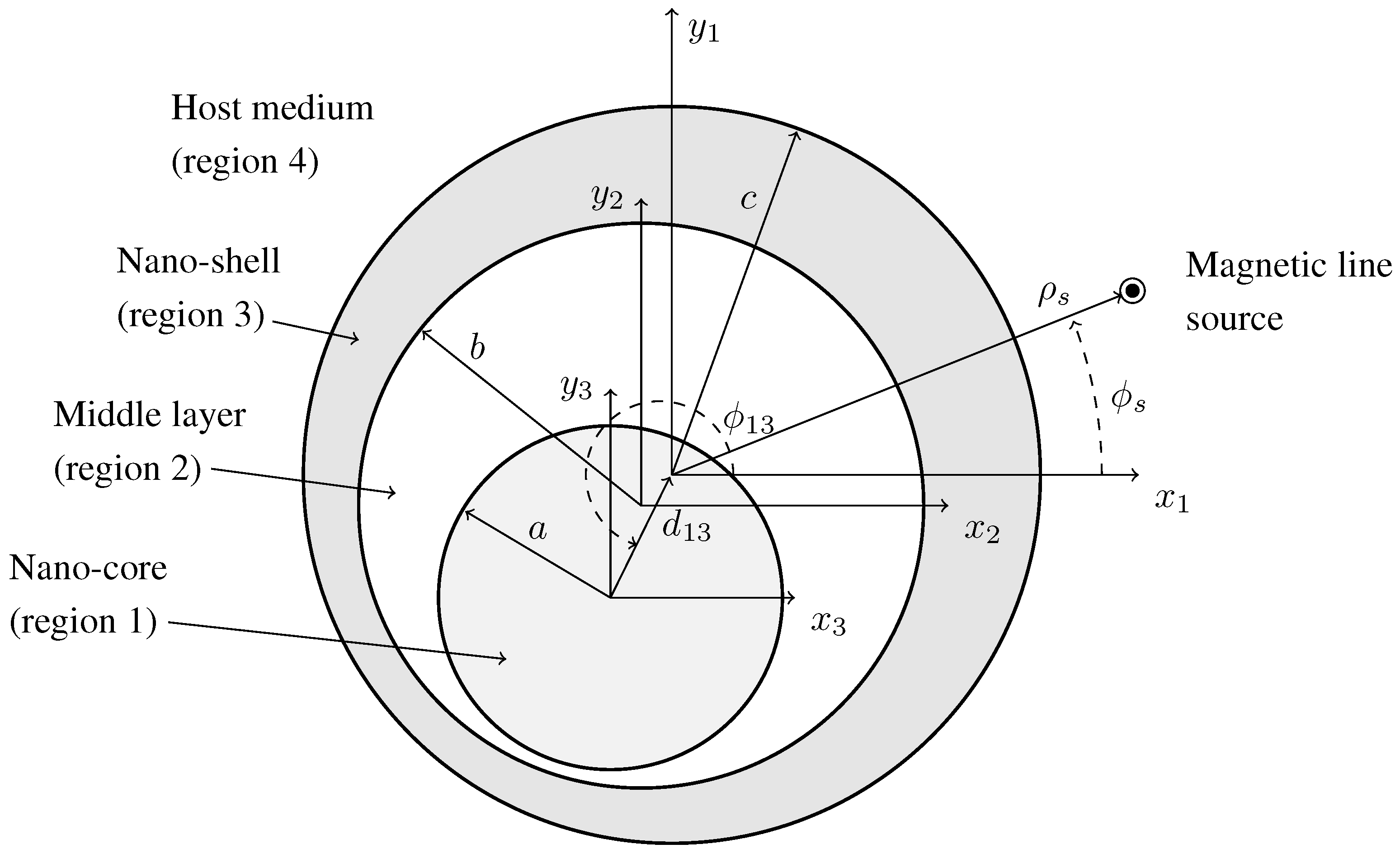
2.1. Configuration

The cross-section of the 3L NP is shown in Figure 1. It is made of a cylindrical nano-core of radius a (Region 1), surrounded eccentrically with a middle layer of outer radius b (Region 2) and a nano-shell of outer radius c (Region 3) and is embedded in an unbounded host medium (region 4). The particle is illuminated by the field of a near-by and infinite magnetic line source (MLS) driven by a constant magnetic current I m (V). The axes of the particle and the MLS are parallel, and the MLS is located in Region 4. The nano-core and nano-shell regions consist of simple and, in general, lossy materials with permittivity ϵ i = ϵ i ' - j ϵ i ' , permeability μ i = μ 0 , and wave number k i = ω ϵ i μ 0 ( i = 1 , 3 ) ; these will be further discussed in Section 3. The middle layer and the host medium are a free-space with the permittivity, ϵ 0 , the permeability, μ 0 , and the wave number k 0 = ω ϵ 0 μ 0 = 2 π / λ , with λ denoting the free-space wavelength. Three Cartesian ( x i , y i , z i ) and the associated cylindrical, ( ρ i , ϕ i , z i ) coordinate systems ( i = 1 , 2 , 3 ) are introduced, such that the z i -axes of the i = 1 , i = 2 and i = 3 coordinate systems coincide with the center of the nano-core, middle layer and nano-shell, respectively. The coordinates of the MLS are ( ρ s , ϕ s ) , while those of the observation points are ( ρ i , ϕ i ) in their respective coordinate system. The eccentricity of the nano-core, designated by the index ( j = 13 ) , and of the middle layer, designated by the index ( j = 12 ) , is described with respect to the first coordinate system ( i = 1 ) by the radial distance d j and its angle ϕ j with respect to the x 1 -axis.
Figure 1. The configuration of the eccentric three-layer NP excited by a near-by magnetic line source.
Photonics 02 00773 g001

2.2. Analytical Solution

We next outline the main steps of the analytical solution pertaining to the configuration shown in Figure 1. The solution is based on the eigenfunction expansion technique. Appropriate addition theorems for radial functions are employed to express the fields in the same coordinate system as required for the application of the boundary conditions. The approach in [38], where plane wave scattering from an eccentric multi-layered circular cylinder has been considered, is presently adopted in the three-layer configuration excited by a near-by MLS.
In terms of the cylindrical wave functions originating at ρ 1 = 0 , the magnetic field of the MLS in Region 4 reads:
H MLS ( ρ 1 , ϕ 1 ) = - z ^ I m ω ϵ 4 4 n = - H n ( 2 ) ( k 4 ρ s ) J n ( k 4 ρ 1 ) e j n ( ϕ 1 - ϕ s ) , for   ρ 1 ρ s n = - H n ( 2 ) ( k 4 ρ 1 ) J n ( k 4 ρ s ) e j n ( ϕ 1 - ϕ s ) , for   ρ 1 ρ s
with J n ( · ) and H n ( 2 ) ( · ) being the Bessel function and the Hankel function of the second kind, respectively, both of order n. For ρ 1 ρ s , Bessel functions were chosen due to their non-singular behavior at ρ 1 = 0 , whereas for ρ 1 ρ s , Hankel functions were chosen in order to represent outward propagating waves. The field generated by the MLS in (1) is the known field and is referred to as the incident field for the 3L NP problem in Figure 1. The unknown scattered field in Region 4 and the unknown total fields inside the 3L NP are also expanded in terms of cylindrical wave functions and have the form:
H i ( ρ i , ϕ i ) = - z ^ I m ω ϵ i 4 n = - h l , n ( ρ i ) e j n ϕ i
where:
h l , n ( ρ i ) = B n 4 H n ( 2 ) ( k 4 ρ 1 ) e - j n ϕ s , for   l = 4 , ρ 1 c A n 3 J n ( k 3 ρ 3 ) + B n 3 H n ( 2 ) ( k 3 ρ 3 ) , for   l = 3 , b ρ 3 c A n 2 J n ( k 2 ρ 3 ) + B n 2 H n ( 2 ) ( k 2 ρ 3 ) , for   l = 2 , a ρ 3 b A n 1 J n ( k 1 ρ 3 ) , for   l = 1 , ρ 3 a
where l is the region number, while A n l and B n l are the unknown expansion coefficients to be determined. The electric fields corresponding to the magnetic fields in (1) and (2) follow at once through the application of the Maxwell–Amperes law E = × H / ( j ω μ ) ; for the sake of brevity, they are not included here. The unknown expansion coefficients, A n l and B n l , are determined by use of the boundary conditions, which require the continuity of the tangential components of the total electric and magnetic fields at the three cylindrical interfaces of the 3L NP at ρ 1 = c , ρ 2 = b and ρ 3 = a . For this to be practical at the interfaces ρ 1 = c and ρ 2 = b , the fields in Regions 2 and 3 (initially expressed in terms of the i = 3 coordinate system) must be translated to the i = 1 and i = 2 coordinate systems. This is accomplished through the addition theorem for cylindrical wave functions of order n [39]. In this way, the application of the boundary conditions leads to a system of linear equations represented by:
Ψ n = M n - 1 Λ n
where M n is the matrix containing the information about the cylindrical waves at the 3L NP interfaces, Ψ n is the vector containing the unknown expansion coefficients of the fields in Regions 2 and 3, while Λ n is the excitation vector, which depends on the location of the MLS, as well as on the value of the cylindrical waves at the ρ 1 = c . With the knowledge of the expansion coefficients in (4), the unknown expansion coefficients in Regions 1 and 4 can be determined. More specific details related to the determination of the unknown expansion coefficients, as well as the explicit form of the matrix M n are found in Appendix A. In the actual implementation, the infinite summations in the field expansions (1) and (2) have been truncated, such that convergence of the resulting expansions was ensured.
Apart from the examinations of the near-field distributions, the performance of the 3L NP will be quantified in terms of the normalized radiation resistance (NRR) and the directivity D. The NRR (in dB) is given by:
NRR = 10 log 10 n = - J n ( k 0 ρ s ) + B n 4 2
and expresses the power radiated by the MLS in the presence of the particle normalized with the power radiated by the MLS alone in free-space. This quantity has been used in our previous studies, e.g., [10] (Chapter 9) and [22]; it is also equivalent to the radiated power ratio introduced initially in the metamaterial-based antenna studies [40] and to the well-known Purcell factor [41].
The directivity represents the ratio of the radiation intensity in a given direction ϕ 1 to the radiation intensity averaged over all directions and is expressed as:
D ( ϕ 1 ) = n = - j n J n ( k 0 ρ s ) + B n 4 e j n ϕ 1 - ϕ s 2 n = - J n ( k 0 ρ s ) + B n 4 2

3. Geometry, Materials and Gain Model

This section specifies the geometric and material parameters, as well as the gain model employed in the study of the 3L NP. With reference to Figure 1, we note that the 3L NP is composed of a silica (SiO 2 ) nano-core, free-space middle layer and a silver (Ag) nano-shell. The radius of the nano-core is set to a = 18 nm; the outer radius of the middle layer is set to b = 24 nm; and the outer radius of the nano-shell is set to c = 30 nm. In the forthcoming investigations, attention is devoted to the influence of the eccentricity achieved through the core displacements relative to the surrounding layers. To this end, we set the eccentricity parameters d 12 = 0 , ϕ 12 = 0 , such that the i = 2 and i = 3 coordinate systems coincide, while the eccentricity parameters d 13 , ϕ 13 are varied. In particular, the core displacements along the positive and negative x 1 -axis (designated as x 13 = ± x nm, with x being the amount of displacement) and along the positive y 1 -axis (designated as y 13 = y nm, with y being the displacement) will be considered.
Due to the nano-scale design (6 nm-thick silver nano-shell), the permittivity of the silver nano-shell is size dependent; this is presently accounted for as described in [20]. To model an active 3L NP, the gain is introduced in the silica nano-core using a canonical, constant frequency, gain model. Following this model, the permittivity of the nano-core is expressed as ϵ 1 = ϵ 0 ( n - j κ ) 2 = ϵ 0 ( n 2 - κ 2 - j 2 n κ ) , where n is the refractive index maintained at the known silica value of n = 2 . 05 1 2 , while the parameter κ < 0 represents the amount of gain included in the nano-core.
In all of the investigations, the MLS is located outside of the particle at ρ s = 35 nm, ϕ s = 0 , and it is driven by a constant magnetic current of I m = 1 V.
A summary of the relevant parameters for the investigated 3L NP is found in Table 1.
Table 1. The material and geometric parameters of the investigated 3L NP excited by a near-by MLS.
Nano-CoreMiddle LayerNano-ShellHost Medium ( a , b , c ) (nm) ( ρ s , ϕ s ) (nm, ° ) I m (V)
SiO2Free-spaceAgFree-space(18, 24, 30)(35, 0)1

4. Results and Discussion

In the present section, we discuss the near- and far-field properties of concentric and eccentric active 3L NPs. First, the NRR and the near-field distributions are shown. At the outset, the concentric 3L NP is discussed, and subsequently, the influence of the layer eccentricity is assessed. Finally, the associated (far-field) directivity results will be discussed. The results in this section have all been obtained by a developed MATLAB code that implements the analytical expressions pertaining to the eccentric 3L NP from Section 2.2. The code was extensively validated by several means. First, it was used to reproduce successfully the known results for the concentric two-layer active NPs in [23]. Second, we also reproduced the below results in Comsol Multiphysics simulation software. A perfect agreement between our results and those obtained by Comsol Multiphysics was obtained; however, the simulations were far more time consuming when done in Comsol Multiphysics. A few representative results from Comsol Multiphysics will be included below to further confirm the correctness of our analytical results and the developed MATLAB code.

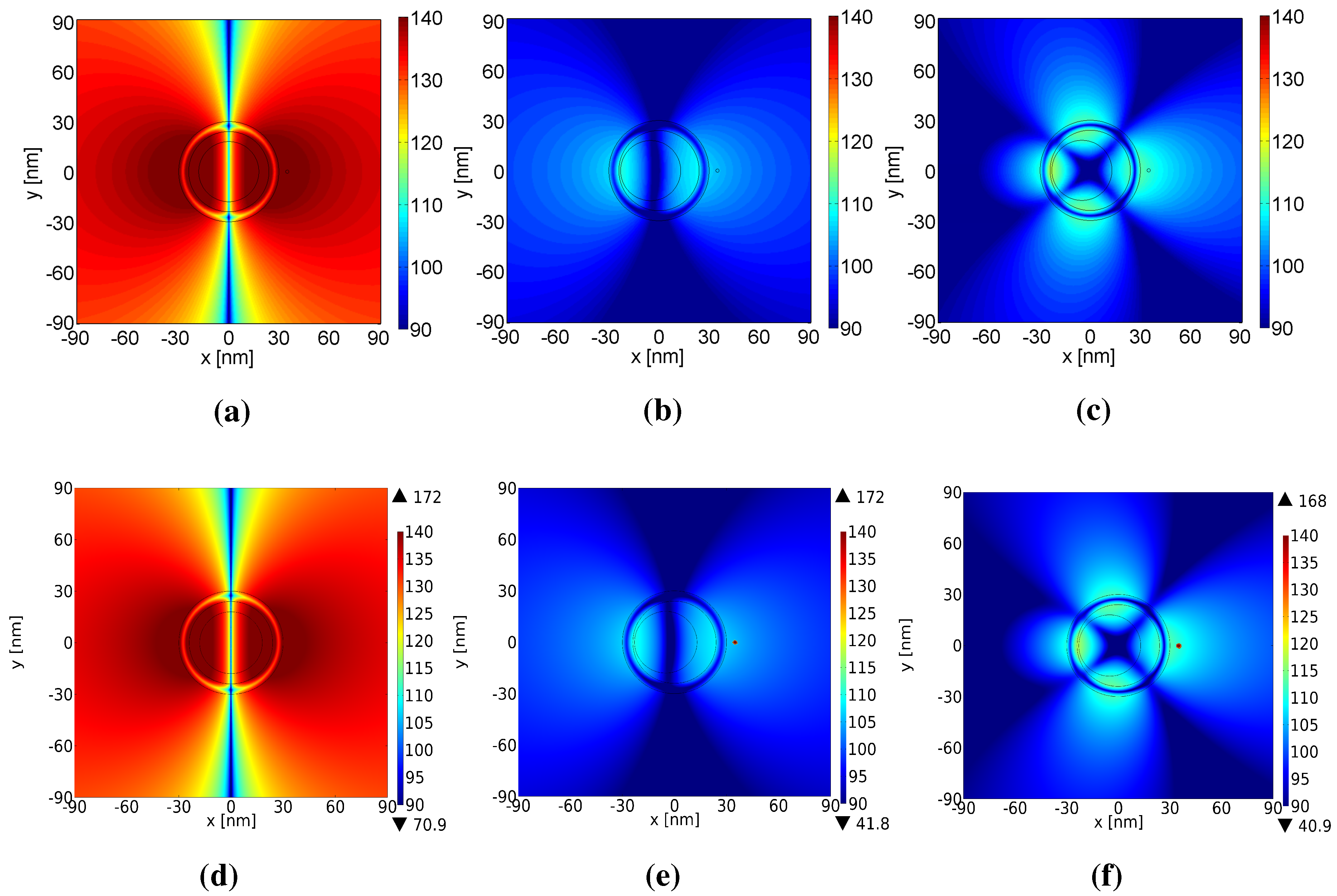
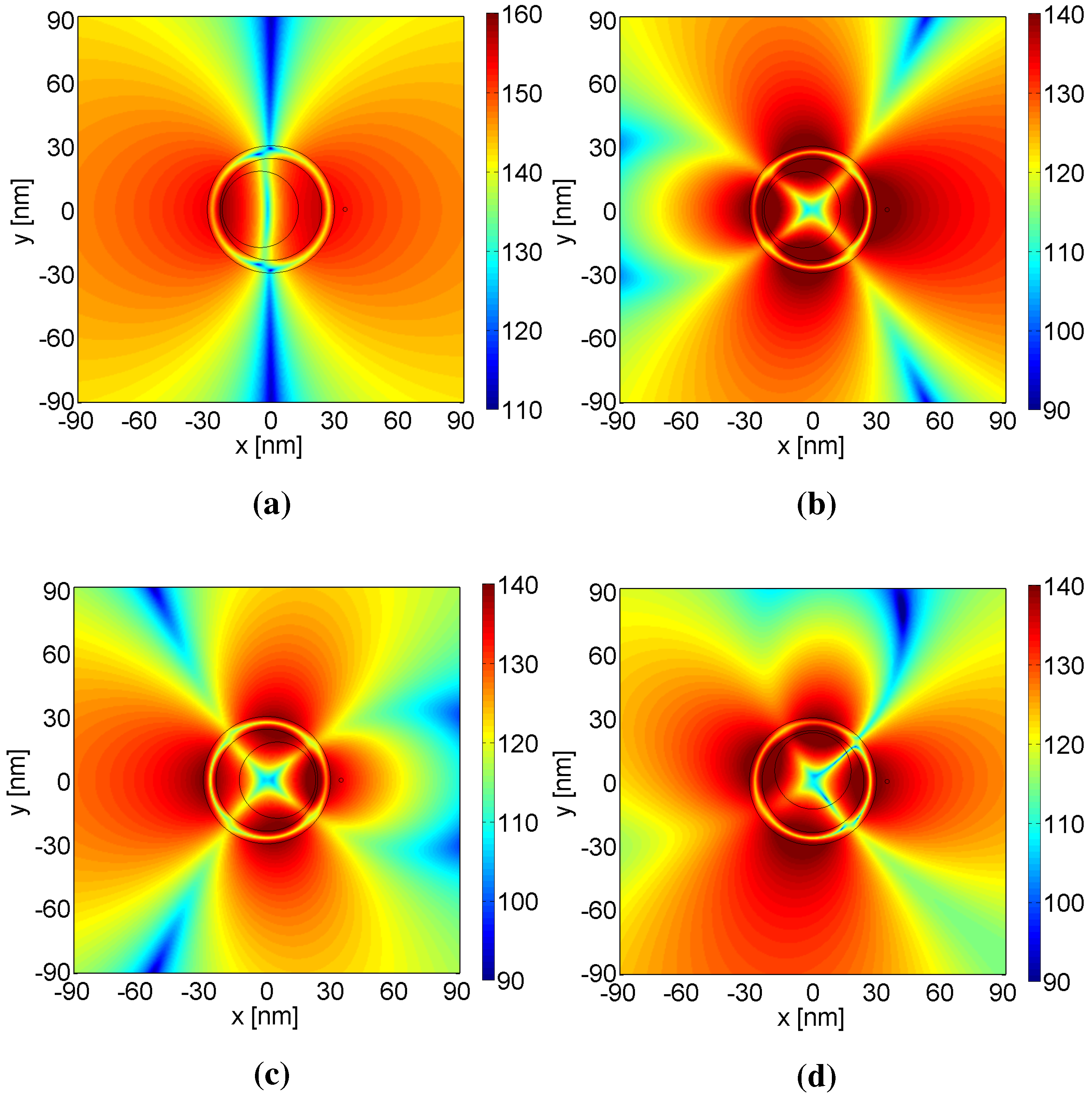
4.1. NRR and Near-Field Distributions

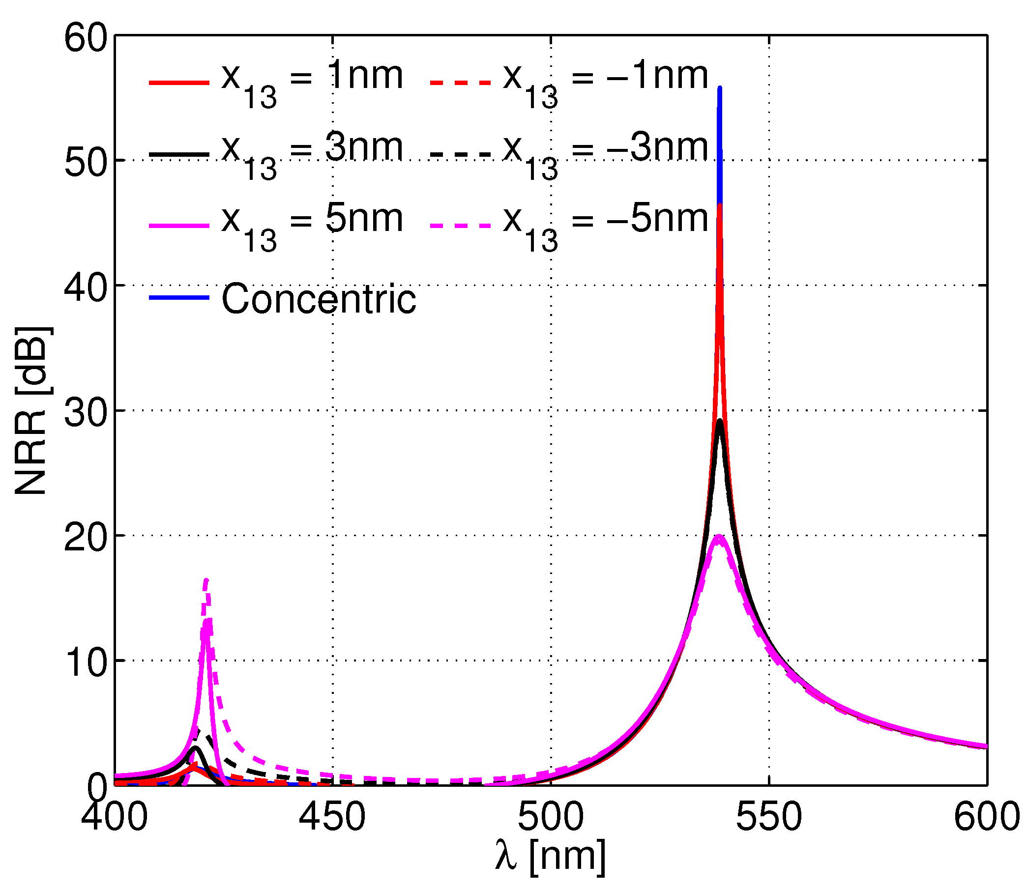
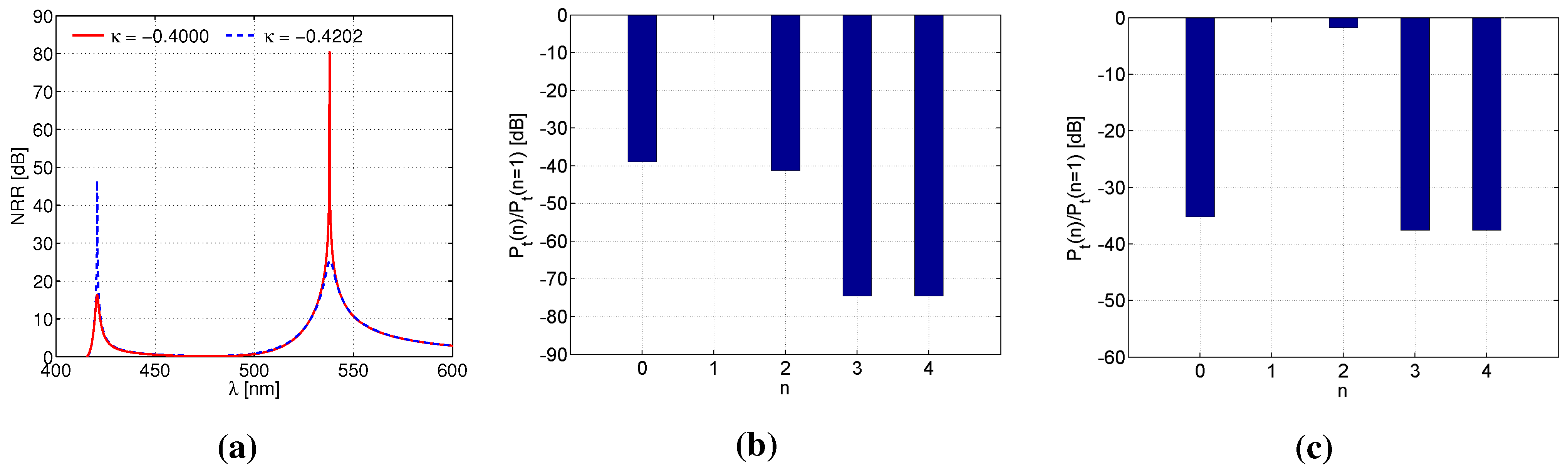
4.1.1. Introducing Eccentricity in Concentric Dipolar Configurations

For a proper value of the parameter κ, a super-resonant state can be found for the 3L NP; at this state, losses in the plasmonic part of the particle are overcome, and large values of the NRR result. For the concentric 3L NP, this state was attained for κ = - 0 . 4409 , and it is illustrated by the very large NRR values shown in Figure 2 as a function of the wavelength λ. Specifically, the maximum NRR is 55 . 8 dB at the wavelength of 538 . 7 nm. To provide insight into the physical mechanism behind the resonant enhancement of the NRR, the total power spectrum of the n-th mode is shown in Figure 3a for the concentric 3L NP. Specifically, the total power in the n = 0 , 1, 2, 3 and 4 modes, normalized by the total power in the n = 1 (dipole) mode, is depicted. Since the vast majority of the power is contained in the dipole mode (for which the bar is then obviously not visible) with only a very negligible portion contained in the other modes, it is clear that its strong excitation leads to the large NRR values. This is also confirmed by the result in Figure 4a, where the quantity 20 log 10 | H | (dB) (with H being the total magnetic field normalized by 1 (V/m) prior to taking the logarithm), clearly shows a strong dipole field distribution. For the sake of the validation of these results, the corresponding numerical result obtained by Comsol Multiphysics is shown in Figure 4d and is found to be in excellent agreement with the result in 4a. A similar electric dipole mode dominated super-resonant behavior in related two-layer active particles was studied previously in [23,36].
Figure 2. The normalized radiation resistance (NRR) as a function of the excitation wavelength λ for the investigated 3L NPs. The results are recorded for κ = - 0 . 4409 , which optimizes the NRR of the concentric 3L NP in the dipole mode operation; concentric and eccentric cases are shown.
Photonics 02 00773 g002
Figure 3. The total power spectrum of the n-th mode, i.e., the total power in the n = 0 , 1, 2, 3 and 4 modes, normalized by the the total power in the dipole ( n = 1 ) mode. (a) Concentric 3L NP, κ = - 0 . 4409 , 538 . 7 nm; (b) eccentric 3L NP, κ = - 0 . 4409 , 538 . 5 nm; (c) eccentric 3L NP, κ = - 0 . 4409 , 421 . 0 nm. For the eccentric cases, the core is displaced by an amount of x 13 = - 5 nm. Refer to the main text for more explanations.
Photonics 02 00773 g003
Figure 4. The magnitude of the magnetic field, 20 log 10 | H | , for the examined 3L NPs. All results are reported for κ = - 0 . 4409 , which optimizes the NRR in the concentric 3L NP. (a) Concentric 3L NP, λ = 538 . 7 nm; (b) eccentric 3L NP, λ = 538 . 5 nm; (c) eccentric 3L NP, λ = 421 . 0 nm. For the eccentric cases, the core is displaced by an amount of x 13 = - 5 nm. The field is shown in a square region of 90 × 90 nm 2 . Curves illustrating the cylindrical surfaces of the 3L NP are also shown. For the sake of the validation of these results, the corresponding numerical results obtained by Comsol Multiphysics are shown in (df) and are found to be in excellent agreement with the results in (a–c) produced by the developed MATLAB code.
Photonics 02 00773 g004
To assess the influence of the core displacements, Figure 2 also shows the NRR for gradual displacements of the core along the x 1 -axis by an amount x 13 = ± ( 1 , 3 , 5 ) nm. Several interesting results are found upon the introduction of the eccentricity. Compared to the concentric case around 539 nm, the NRR decreases with the increasing core displacements; e.g., the peak NRR is 19 . 4 dB at 538 . 5 nm for the x 13 = - 5 nm core displacement. In all cases, the resonant wavelength remains the same (or almost the same) as in the concentric case. The total power in the n = 0 , 1, 2, 3 and 4 modes, normalized by the the total power in the dipole mode, is shown in Figure 3b for the x 13 = - 5 nm displacement ( 538 . 5 nm). Clearly, the dipole mode still dominates the response in this eccentric 3L NP. However, the other modes now contribute somewhat more than in the concentric case. The eccentricity thus causes a slightly stronger excitation of these other modes, leading to a reduced strength of the dipole mode. This is also confirmed by Figure 4b, where the magnetic near-field is shown for the x 13 = - 5 nm displacement; the field is still dominated by the dipole mode, although its strength is reduced, and the pattern is slightly asymmetric due to the increased presence of other modes (the corresponding numerical result obtained by Comsol Multiphysics is shown in Figure 4e and is found to be in excellent agreement with the result in Figure 4b).
With the decreasing NRR around 539 nm, an increasing core displacement moreover induces additional peaks at significantly shorter wavelengths. This is most so for the largest core displacements; particularly along the negative x 1 -axis (see Figure 2), where a peak of 16 . 4 dB is found at 421 . 0 nm for x 13 = - 5 nm. The corresponding total power in the n = 0 , 1, 2, 3 and 4 modes, normalized by the the total power in the dipole mode, is depicted in Figure 3c. While the dipole mode is still the largest one, the eccentricity induces a more profound n = 0 (monopole) mode than before, and even more interestingly, it induces at this wavelength a very strong n = 2 (quadrupole) mode that is comparable in strength to the dipole mode. The combination of the modes, in particular the dipole and quadrupole ones, leads to a very interesting magnetic near-field shown in Figure 4c for the x 13 = - 5 nm core displacement. The near-field distribution is asymmetric and rather directive, with a main beam directed along the positive x 1 direction; this is opposite of the direction of the core displacement (the corresponding numerical result obtained by Comsol Multiphysics is shown in Figure 4f and is found to be in excellent agreement with the result in Figure 4c).
It is interesting to note how the introduction of eccentricity in a 3L NP, initially designed to operate in a dipole mode, causes the appearance of other modes; in particular, the quadrupole (higher order) mode comparable in strength to the dipole mode is excited. The simultaneous excitation of these modes can form interesting asymmetric, rather directive and enhanced near-field distributions.
The super-resonant values of the NRR (and the corresponding wavelengths) reported in Figure 2 for the 3L NP are summarized in Table 2.
Table 2. The resonant wavelength and the NRR values for the super-resonant states of the 3L NP reported in Figure 2. The core is displaced along the positive and negative x 1 -axis. The subscript l refers to the longer wavelength where the dipole mode dominates, while s refers to the shorter wavelength, where other, particularly quadrupole, modes are excited together with the dipole mode.
x 13 (nm) λ s (nm)NRR (dB) λ l [nm]NRR (dB)
5420.913.1538.519.8
3418.82.9538.729.1
1418.11.7538.746.4
0418.31.3538.755.8
−1418.71.4538.746.3
−3419.54.5538.728.8
−5421.016.4538.519.4

4.1.2. Optimization of Eccentric Configurations

Thus far, we have found that introducing the eccentricity in the above, initially concentric 3L NP with κ = - 0 . 4409 lowers the NRR at the dipole resonance (around 539 nm), while simultaneously introducing an additional peak around 421 nm, where both the dipole and the quadrupole modes are comparably excited. In the case of x 13 = - 5 nm displacement, the recorded peak values of the NRR were 19 . 4 dB at 538 . 5 nm and 16 . 4 dB at 421 nm; cf. Table 2. It is, however, useful to note that each of these eccentric 3L NPs can be further gain optimized to yield a large NRR response at either of the two wavelengths of interest, as shown in Figure 5a for the largest, x 13 = - 5 nm, core displacement along the negative x 1 -axis. The maximum NRR is found at 538 . 7 nm for κ = - 0 . 4000 and at 420 . 7 nm for κ = - 0 . 4202 . The corresponding total power in the n = 0 , 1, 2, 3 and 4 modes, normalized by the the total power in the dipole mode, is shown in Figure 5b,c; the dipole mode is by far the strongest mode at 538 . 7 nm in the eccentric 3L NP for κ = - 0 . 4000 , while it blends effectively with the quadrupole mode at 420 . 7 nm in the eccentric 3L NP for κ = - 0 . 4202 . These power spectra largely correspond to those discussed above for the non-optimized eccentric 3L NP, except that in the present case, the n = 0 (monopole) mode is considerably more suppressed relative to the non-optimized eccentric 3L NPs. Thus, the dipole and quadrupole modes dominate the response even more in the gain-optimized eccentric 3L NP around421 nm than in the previously-discussed cases.
Figure 5. (a) The NRR as a function of the excitation wavelength λ for the eccentric 3L NPs ( x 13 = - 5 nm), which optimize the NRR at the two resonances of interest (around 539 nm and 421 nm). The corresponding total power spectrum of the n-th mode, i.e., the total power in the n = 0 , 1, 2, 3 and 4 modes, normalized by the the total power in the dipole ( n = 1 ) in the gain-optimized eccentric 3L NPs. (b) κ = - 0 . 4000 , 538 . 7 nm; (c) κ = - 0 . 4202 , 420 . 7 nm. The core is displaced by an amount of x 13 = - 5 nm. Refer to the main text for more explanations.
Photonics 02 00773 g005
The magnetic fields corresponding to the peaks in Figure 5a are shown in Figure 6a,b. A strong dipole mode, although with some asymmetry, is in evidence at 538 . 7 nm; cf. Figure 6a. The field in Figure 6b, recorded at 420 . 7 nm, is similar in shape, but significantly enhanced in strength, relative to the one found in Figure 4c. It is asymmetric and rather directive with most of the field radiated in the x 1 > 0 half-space in the direction opposite the core displacement direction.
The influence of the nano-core displacements in other directions on the directive properties of the 3L NPs has also been investigated. By displacing the core in the positive x 1 -direction or even along the y 1 -axis, the main beam direction of the resulting field distribution is effectively shifted, as shown in Figure 6c,d. The main beam again occurs in the direction opposite the core displacement direction (for the displacement along the positive x 1 -axis) and almost opposite of it (for the displacement along the positive y 1 -axis); the latter being due to the asymmetric MLS location with respect to the 3L NP. As a consequence, the introduction of the eccentricity in the presently examined 3L NPs offers, through excitation of dipole and quadrupole modes, a very interesting means of attaining rather directive near-field distributions, as well as the possibility to effectively steer its main radiation direction by the direction of the core displacements.
Figure 6. The magnitude of the magnetic field, 20 log 10 | H | , for the optimized eccentric 3L NPs. The result in (a) is for κ = - 0 . 4000 , λ = 538 . 7 nm and represents the field that leads to the maximum NRR at 538 . 7 nm in Figure 5a. The results in (bd) are for κ = - 0 . 4202 , λ = 420 . 7 nm. The result in (b) represents the field corresponding to the maximum NRR at 420 . 7 nm in Figure 5a, i.e., x 13 = - 5 nm, while the displacement in (c) is x 13 = 5 nm and in (d) y 13 = 5 nm. The field is shown in a square region of 90 × 90 nm 2 . Curves illustrating the cylindrical surfaces of the 3L NP are also shown.
Photonics 02 00773 g006

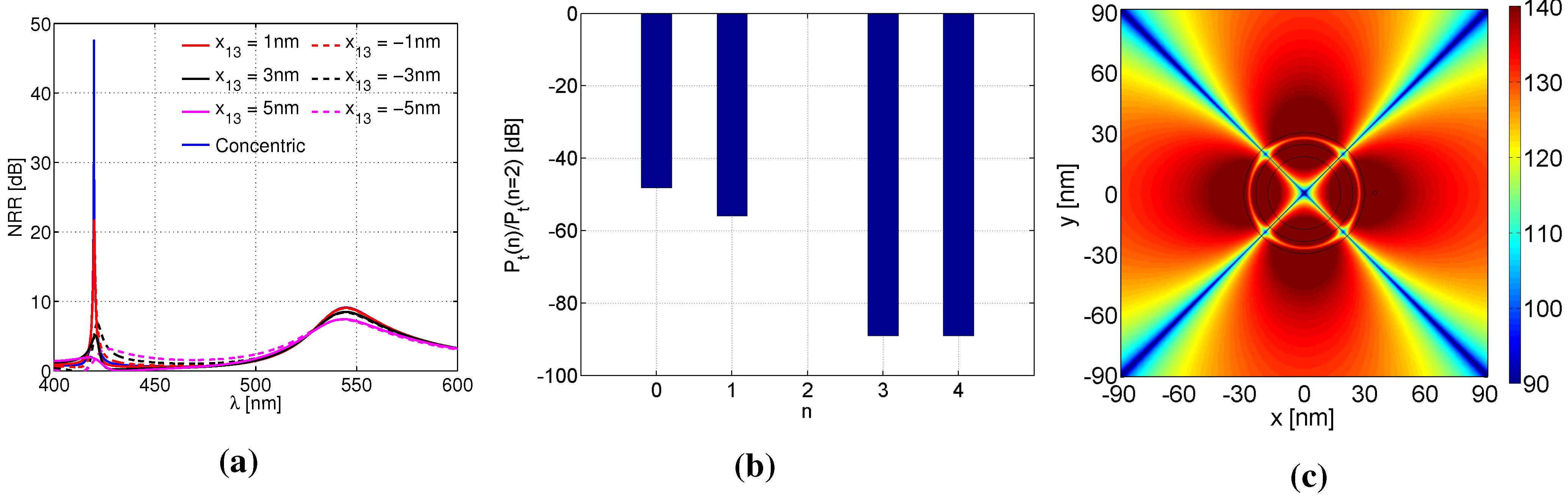
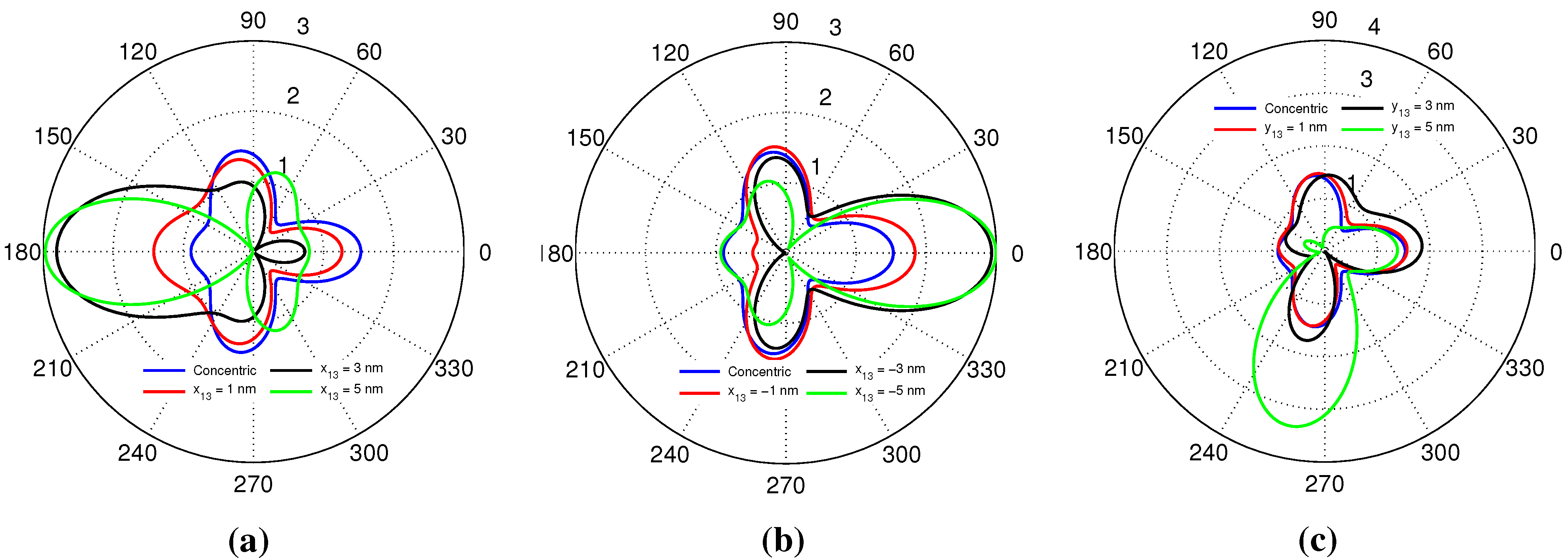
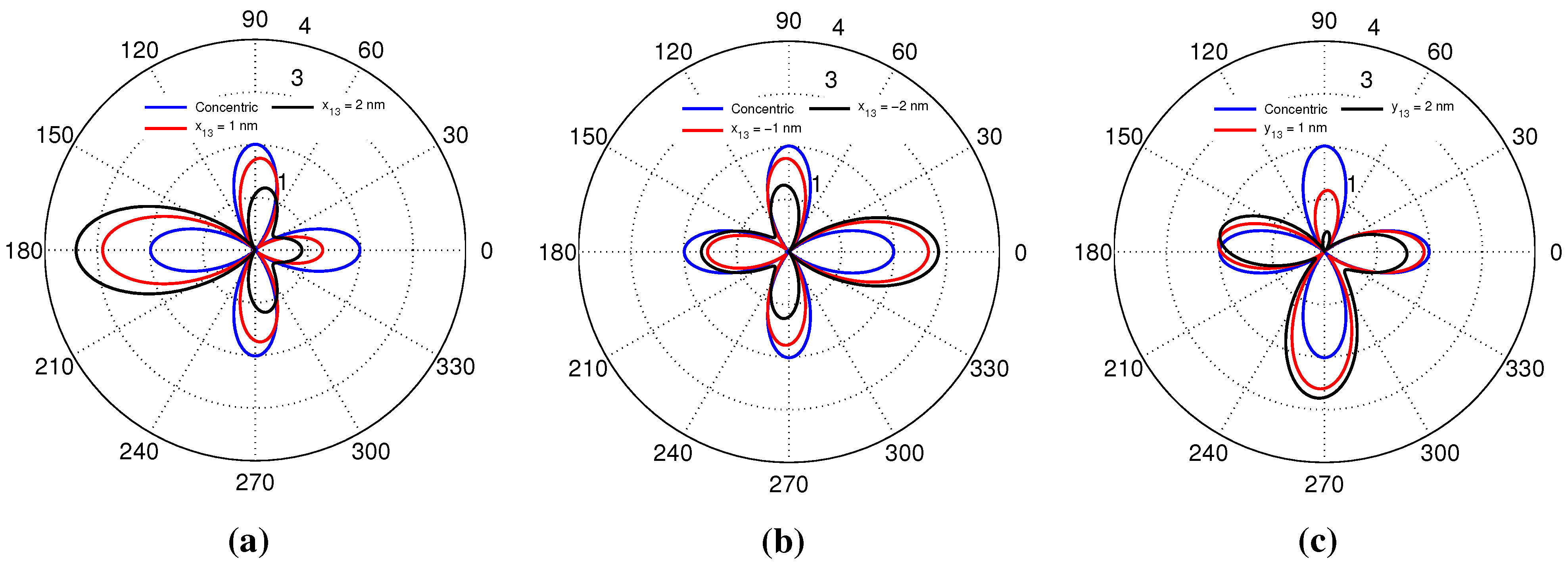
4.1.3. Introducing Eccentricity in Concentric Quadrupolar Configurations
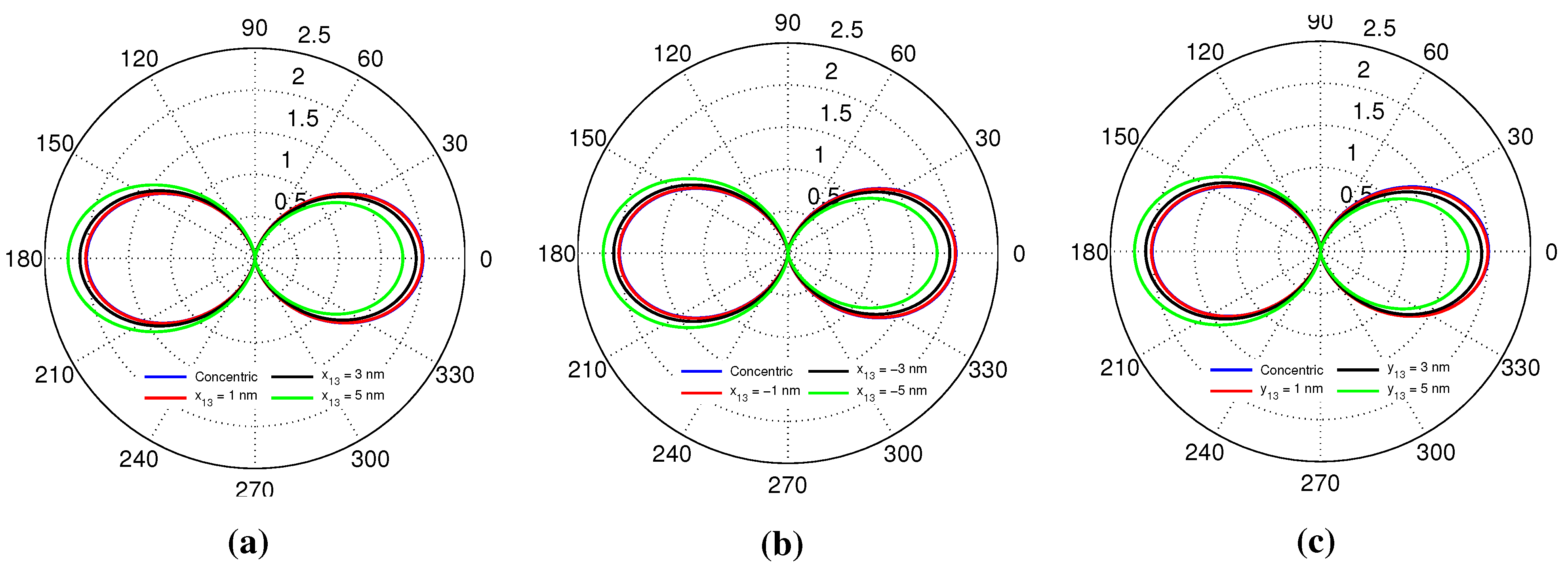
The above discussion was initiated through a consideration of a concentric 3L NP designed to provide a strong dipole mode response and was subsequently extended to assess the influence of the eccentricity. By proper adjustments of the parameter κ, the concentric 3L NP can likewise be optimized to give a significantly larger NRR response around the shorter wavelength of 421 nm. This is illustrated in Figure 7a, where a large peak in the NRR is found for κ = - 0 . 6202 in the concentric case. The corresponding total power spectrum of the n-th mode (the total power in the n = 0 , 1, 2, 3 and 4 modes, normalized by the the total power in the n = 2 (quadrupole) mode) is shown in Figure 7b, from which it clearly follows that the reported peak in the NRR is due to the excitation of a strong quadrupole mode (for which the bar is then obviously not visible) at this wavelength. This is also confirmed by the magnetic field result in Figure 7c, where a strong quadrupole mode is found. It is important to note that the resonances in this case are very susceptible to even the smallest core displacements; e.g., the NRR decreases to around 6 dB at x 13 = - 3 nm. Even though the power spectra are not included presently for these eccentricities, they have revealed a significantly increased presence of other than the quadrupole mode (particularly the monopole and dipole modes) upon the introduction of the eccentricity in the present 3L NPs. However, in all cases, the quadrupole mode remained the strongest.
Figure 7. The NRR as a function of the excitation wavelength λ for the concentric and eccentric 3L NPs for κ = - 0 . 6202 ; this value optimizes the NRR in the concentric 3L NP at 419 . 8 nm. (b) The total power spectrum in the n-th mode, i.e., the total power in the n = 0 , 1, 2, 3 and 4 modes, normalized by the the total power in the quadrupole mode ( n = 2 ) mode for the concentric 3L NP corresponding to the peak NRR in (a). (c) The magnitude of the magnetic field, 20 log 10 | H | , for the concentric 3L NP corresponding to the peak NRR in (a). The field is shown in a square region of 90 × 90 nm 2 . Curves illustrating the cylindrical surfaces of the 3L NP are also shown.
Photonics 02 00773 g007
The present analysis demonstrated a very interesting means to effectively tailor (enhance, reshape and steer) the near-field response through the excitation of several modes by introducing the eccentricity in the examined 3L NPs. Particularly, cases were identified with comparable simultaneous excitation of dipole and quadrupole modes; they possessed enhanced NRRs, as well as enhanced and directive near-fields, with the direction of the main beams controlled by the direction of the core displacement.

4.2. Directivity

Having described how the eccentricity influences the near-field distribution in the examined 3L NPs, we next show that similar results hold also for their far-field properties. To this end, Figure 8 shows the directivity (6) of the concentric and eccentric 3L NPs for κ = - 0 . 4409 ; this corresponds to the NRR results in Figure 2 at the longer wavelength around 539 nm (see also Table 2) where the dipole mode dominates. For the directivity investigations, core displacements x 13 = ± ( 1 , 3 , 5 ) nm and y 13 = ( 1 , 3 , 5 ) nm have been considered. In the concentric case, a symmetric dipole is excited with maximum directivity, D max = 2 in the ϕ 1 = 0 and 180 directions. In all eccentric cases, an increased eccentricity shifts the directivity slightly so that its maximum (slightly above two) occurs for ϕ 1 = 180 . The present directivity results are in line with the corresponding near-field distributions discussed in Section 4.1.
Figure 8. The directivity of the concentric and eccentric 3L NPs for κ = - 0 . 4409 at the longer wavelength around 539 nm where the dipole mode dominates. The directivity is shown for core displacements along (a) the positive and (b) the negative x 1 -axis, as well as along (c) the positive y 1 -axis for 1, 3 and 5 nm.
Photonics 02 00773 g008
Evaluating next the directivities of the same 3L NP, but at the shorter wavelength (see also Table 2) where the dipole and quadrupole modes are of comparable strength, the results in Figure 9 are obtained. As the core displacement increases, an increasingly distinct main beam is formed in the direction opposite the core displacement direction (or almost opposite of it for the displacement along the y 1 -axis). For displacements along the x 1 -axis, both 3- and 5-nm displacements yield rather directive patterns with D max around three; thus, the directivity is enhanced relative to that offered by the dipole mode alone. This is moreover interesting in the former case, since the resulting NRR value is low (3 dB and 4.5 dB); cf. Table 2. For the displacements along the y 1 -axis, only the largest eccentricity leads to a highly directive pattern with D max exceeding three. The directivity pattern for the largest core displacements along the negative x 1 -axis is in agreement with the corresponding near-field results reported in Figure 4c. It is also useful to note that similar directivities, not included here, are obtained for the 3L NPs optimized in the eccentric case to give a peak NRR at the shorter wavelength; the corresponding near-fields are shown in Figure 6b–d.
Figure 9. The directivity of the concentric and eccentric 3L NPs for κ = - 0 . 4409 at the shorter wavelength around 421 nm where the dipole and quadrupole modes are comparable. The directivity is shown for core displacements along (a) the positive and (b) the negative x 1 -axis, as well as along (c) the positive y 1 -axis for 1, 3 and 5 nm.
Photonics 02 00773 g009
As with the discussion of the near-fields in Section 4.1, the initial directivity discussion above was based on a super-resonant 3L NP initially designed to give a dipole-dominated response. If, however, one takes the outset in the 3L NP optimized in the concentric case for a quadrupole mode (see Figure 7 for the NRR, power spectrum and near-field results), the directivities in Figure 10 are obtained in the concentric and the indicated eccentric cases. In the concentric case, the directivity is, as expected, a symmetric quadrupole (with D max = 2 ). As the core displacement increases, the trend follows roughly the previously-reported results; asymmetry in the pattern is introduced (due to several modes contributing, but with the quadrupole mode being the strongest), resulting in the formation of a main beam (with enhanced directivity) in the direction opposite the core displacement direction. However, the patterns show a greater consistency in their form as the displacement increases, and the main beam appears to be narrower than in the previous cases. Note, however, that only displacements up to 2 nm are considered presently, due to the high sensitivity of the quadrupole mode to large displacements, which were found to result in no enhancements of the NRR; cf. our discussions at the end of Section 4.1.
In conclusion, the introduction of the eccentricity in the presently-investigated 3L NPs introduces the required asymmetry in the particle and, thus, causes a simultaneous appearance of several modes. This enables effective tailoring (enhancement, reshaping and steering) of not only the near-field radiation, but also their far-field directivities. Appropriate core displacements in a specified direction can lead to cases where, e.g., dipole and quadrupole modes are comparably excited, with the outcome of rather directive patterns in the direction opposite or almost opposite the core displacement direction. These effects were found to be more pronounced the larger the core displacement is; at the same time, relatively large NRR values were attained implying that a large amount of power is extracted from the near-by MLS and is thus radiated in the direction controlled by the core displacement direction. The investigated 3L NP may therefore serve as an alternative candidate to attain the directive near-, as well as far-field radiation properties relative to solutions proposed in, e.g., [25,26,27,28,29,30,31,32,33,34,35].
Figure 10. The directivity of the concentric and eccentric 3L NPs for κ = - 0 . 6202 at the shorter wavelength around 421 nm. The directivity is shown for core displacements along (a) the positive and (b) the negative x 1 -axis, as well as along (c) the positive y 1 -axis for 1, 3 and 5 nm.
Photonics 02 00773 g010

5. Summary and Conclusions

Resonant properties of three-layer active concentric and eccentric nano-particles comprised of a gain-impregnated silica core, free-space middle layer, coated by a silver shell, were investigated presently for magnetic line source excitation. The problem was solved analytically by employing the eigenfunction expansion technique, and the configuration was subsequently thoroughly investigated through examinations of the resulting near- and far-field results. In particular, the influence of eccentricity, achieved through the silica core displacements, on the radiated power, near-field distributions and directivity for a variety of concentric and eccentric nano-particles was assessed.
It was demonstrated that introducing the eccentricity in a nano-particle, which was initially designed to excite a super-resonant, dipole-dominated state in the concentric configuration (with large values of the radiated power), causes a progressively larger excitation of other, including higher order, modes. This was found to be most pronounced for the largest core displacement. Specifically, careful power spectrum calculations revealed that eccentric nano-particle configurations exist with comparable simultaneous excitations of dipole and quadrupole modes at a specific wavelength; this combined excitation was accompanied by large values of the radiated power and, even more notably, enhanced and rather directive near- and far-field (directivity) patterns. The main beam direction of these patterns was found to be effectively tailored (enhanced, reshaped and steered) by the direction and the amount of the silica core displacement. By further adjustments of the gain inside the silica core, the eccentric nano-particles could be optimized to boost their near-field response and the radiated power. Similar results upon the introduction of the eccentricity were found for nano-particles, which were initially designed to excite a strong quadrupole mode in the corresponding concentric configuration. However, such designs proved more sensitive to even the smallest displacements of the core.
The results of this manuscript demonstrate that eccentric nano-particles can be used for the synthesis of very directive sub-wavelength antennas; the key behind the operation is the eccentricity, which introduces the needed asymmetry required for the excitation of other, including higher order, modes. Thus, as noted elsewhere in the manuscript, the investigated three-layer active and eccentric nano-particles offer an interesting route of achieving directive near- and far-field radiation properties relative to several of the existing solutions [25,26,27,28,29,30,31,32,33,34,35].
Future work on eccentrically-layered nano-particles will address the influence of the source location on their characteristics, as well as investigations of array configurations of the presently-investigated three-layer nano-particles to further increase their directivity response. Moreover, the extension of the eccentricity concepts to the more realistic spherical geometries will be pursued in the near future.

Author Contributions

The idea of using eccentric nano-particles to tailor the near- and far-field properties was conceived by Samel Arslanagić (SA). The analytical solution is due to both authors, whereas the MATLAB code, as well as the Comsol Multiphysics model of the configuration was implemented by Rasmus Ø. Thorsen (RØT). In a close discussion with SA, RØT computed all of the presented results, whereas SA wrote the major part of the manuscript.

Conflicts of Interest

The authors declare no conflict of interest.

A. Determination of the Unknown Expansion Coefficients

The present Appendix contains the steps necessary to determine the expansion coefficients of the unknown fields due to the 3L NP. The employed field expansions have been discussed in Section 2.2. The application of the boundary conditions, requiring the continuity of the tangential components of the total electric and magnetic fields at the various interfaces, yields the following equations:
ϵ 4 J n ( k 4 a ) A n 4 - ϵ 3 J n ( k 3 a ) A n 3 - ϵ 3 H n ( 2 ) ( k 3 a ) B n 3 = 0
k 4 J n ' ( k 4 a ) A n 4 - k 3 J n ' ( k 3 a ) A n 3 - k 3 H n ( 2 ) ( k 3 a ) B n 3 = 0
at the nano-core interface, ρ 3 = a , and:
ϵ 3 n = - J q - n ( k 3 d 23 ) A n 3 J q ( k 3 b ) + B n 3 H q ( 2 ) ( k 3 b ) e - j ( q - n ) ϕ 23 = ϵ 2 n = - J q - n ( k 2 d 23 ) A n 2 J q ( k 2 b ) + B n 2 H q ( 2 ) ( k 2 b ) e - j ( q - n ) ϕ 23
k 3 n = - J q - n ( k 3 d 23 ) A n 3 J q ' ( k 3 b ) + B n 3 H q ( 2 ) ( k 3 b ) e - j ( q - n ) ϕ 23 = k 2 n = - J q - n ( k 2 d 23 ) A n 2 J q ' ( k 2 b ) + B n 2 H q ( 2 ) ( k 2 b ) e - j ( q - n ) ϕ 23
at the intermediate interface, ρ 2 = b , and:
ϵ 1 H q ( 2 ) ( k 1 ρ s ) J q ( k 1 c ) + B q 1 H q ( 2 ) ( k 1 c ) e - j q ϕ s = ϵ 2 n = - J q - n ( k 2 d 13 ) A n 2 J q ( k 2 c ) + B n 2 H q ( 2 ) ( k 2 c ) e - j ( q - n ) ϕ 13
k 1 H q ( 2 ) ( k 1 ρ s ) J q ' ( k 1 c ) + B q 1 H q ( 2 ) ( k 1 c ) e - j q ϕ s = k 2 n = - J q - n ( k 2 d 13 ) A n 2 J q ' ( k 2 c ) + B n 2 H q ( 2 ) ( k 2 c ) e - j ( q - n ) ϕ 13
at the external interface, ρ 1 = c . In the above equations, the prime denotes the derivative with respect to the entire argument of the function. Moreover, in (8a) and (8b), the fields expressed in terms of the i = 3 coordinate system were translated to the i = 2 coordinate system using the addition theorem for cylindrical wave functions of order n [39]. Similarly, in (9a) and (9b), the fields expressed in terms of the i = 3 coordinate system were translated into the i = 1 coordinate system. The solution of the unknown expansion coefficients can be obtained by proper manipulation of the above expressions, as described next. First, consider the nano-core interface. Equations (7a) and (7b) are used to eliminate A n 4 , and by rather straightforward, but lengthy calculations, the resulting expression takes the form of:
τ 1 n A n 3 + τ 2 n B n 3 = 0
where:
τ 1 n = ϵ 3 ϵ 4 J n ( k 3 a ) J n ( k 4 a ) - k 3 k 4 J n ' ( k 3 a ) J n ' ( k 4 a )
τ 2 n = ϵ 3 ϵ 4 H n ( 2 ) ( k 3 a ) J n ( k 4 a ) - k 3 k 4 H n ( 2 ) ( k 3 a ) J n ' ( k 4 a )
Next, consider the intermediate interface. Equations (8a) and (8b) can be rewritten to take the form of:
n = - - χ 1 2 ( q , n ) A n 2 - χ 2 2 ( q , n ) B n 2 + χ 1 3 ( q , n ) A n 3 + χ 2 3 ( q , n ) B n 3 = 0
n = - - χ 3 2 ( q , n ) A n 2 - χ 4 2 ( q , n ) B n 2 + χ 3 3 ( q , n ) A n 3 + χ 4 3 ( q , n ) B n 3 = 0
where:
χ 1 ν ( q , n ) = ϵ ν J q - n ( k ν d 23 ) J q ( k ν b ) e - j ( q - n ) ϕ 23
χ 2 ν ( q , n ) = ϵ ν J q - n ( k ν d 23 ) H q ( 2 ) ( k ν b ) e - j ( q - n ) ϕ 23
χ 3 ν ( q , n ) = k ν J q - n ( k ν d 23 ) J q ' ( k ν b ) e - j ( q - n ) ϕ 23
χ 4 ν ( q , n ) = k ν J q - n ( k ν d 23 ) H q ( 2 ) ( k ν b ) e - j ( q - n ) ϕ 23
with ν = 2 , 3 . Finally, consider the external interface. Equations (9a) and (9b) are used to eliminate B n 1 , and by tedious manipulations, the resulting expression is simplified to yield:
n = - ψ 1 ( q , n ) A n 2 + ψ 2 ( q , n ) B n 2 = ζ q
where:
ψ 1 ( q , n ) = J q - n ( k 2 d 13 ) ϵ 2 ϵ 1 J q ( k 2 c ) H q ( 2 ) ( k 1 c ) - k 2 k 1 J q ' ( k 2 c ) H q ( 2 ) ( k 1 c ) e j ( q ϕ s - ( q - n ) ϕ 13 )
ψ 2 ( q , n ) = J q - n ( k 2 d 13 ) ϵ 2 ϵ 1 H q ( 2 ) ( k 2 c ) H q ( 2 ) ( k 1 c ) - k 2 k 1 H q ( 2 ) ( k 2 c ) H q ( 2 ) ( k 1 c ) e j ( q ϕ s - ( q - n ) ϕ 13 )
ζ q = H q ( 2 ) ( k 1 ρ s ) J q ( k 1 c ) H q ( 2 ) ( k 1 c ) - J q ' ( k 1 c ) H q ( 2 ) ( k 1 c )
Equations (10), (12) and (14) make a system of linear equations for the unknown expansion coefficients, which can be written as:
ψ 1 ( q , n ) ψ 2 ( q , n ) 0 0 - χ 1 2 ( q , n ) - χ 2 2 ( q , n ) χ 1 3 ( q , n ) χ 2 3 ( q , n ) - χ 3 2 ( q , n ) - χ 4 2 ( q , n ) χ 3 3 ( q , n ) χ 4 3 ( q , n ) 0 0 τ 1 n τ 2 n A n 2 B n 2 A n 3 B n 3 = ζ q 0 0 0
where ψ p ( p = 1 , 2 ) is a matrix formulation of (15a) and (15b), χ i ν ( i = 1 , 2 , 3 , 4 ) is a matrix formulation of the expressions in (13), τ p n is a diagonalized matrix comprised of elements (11), A n ν and B n ν are vectors containing the expansion coefficients and ζ q is a vector representation of (15c). The solution of (16) can be written in a compact notation as:
M n Ψ n = Λ n Ψ n = M n - 1 Λ n
where M n is the matrix containing the information about the cylindrical waves at the 3L NP interfaces, Ψ n is the vector containing the unknown expansion coefficients of the fields in Regions 2 and 3, while Λ n is the excitation vector, which depends on the location of the MLS, as well as on the value of the cylindrical waves at the ρ 1 = c interface.
The solution of (17) yields the unknown expansion coefficients in Regions 2 and 3. When these are known, the expansion coefficients in Regions 1 and 4 are obtained by solving (7a) and (9a), respectively, as:
A n 4 = ϵ 3 ϵ 4 J n ( k 3 a ) A n 3 + H n ( 2 ) ( k 3 a ) B n 3 J n ( k 4 a ) ,
B n 1 = ϵ 2 ϵ 1 n = - J q - n ( k 2 d 13 ) A n 2 J q ( k 2 c ) + B n 2 H q ( 2 ) ( k 1 c ) × e - j ( q - n ) ϕ 13 + j q ϕ s - H q ( 2 ) ( k 1 ρ s ) J q ( k 1 c ) 1 H q ( 2 ) ( k 1 c )
Note that identical coefficients could be obtained by solving (7b) and (9b) instead.

References

  1. Choi, I.; Choi, Y. Plasmonic nanosensors: Review and prospect. IEEE J. Sel. Top. Quant. Electron. 2012, 18, 1110–1121. [Google Scholar] [CrossRef]
  2. Hill, M.T. Status and prospects for metallic and plasmonic nano-lasers. J. Opt. Soc. Am. B 2010, 27, B36–B44. [Google Scholar] [CrossRef]
  3. Engheta, N. Circuits with light at nanoscale: Optical nanocircuits inspired by metamaterials. Science 2007, 317, 1698–1702. [Google Scholar] [CrossRef] [PubMed]
  4. Catchpole, K.R.; Polman, A. Plasmonic solar cells. Opt. Express 2008, 16, 21793–21800. [Google Scholar] [CrossRef] [PubMed]
  5. Atwater, H.A.; Polman, A. Plasmonics for improved photovoltaic devices. Nat. Mater. 2013, 9, 205–213. [Google Scholar] [CrossRef] [PubMed]
  6. Jain, P.K.; Huang, X.; El-Sayed, I.H.; El-Sayed, M.A. Noble metals on the nanoscale: Optical and photothermal properties and some applications in imaging, sensing, biology, and medicine. Acc. Chem. Res. 2008, 41, 1578–1586. [Google Scholar] [CrossRef] [PubMed]
  7. Sikdar, D.; Rukhlenko, I.D.; Cheng, W.; Premaratne, M. Optimized gold nanoshell ensambles for biomedical applications. Nanoscale Res. Lett. 2013, 8, 142–146. [Google Scholar] [CrossRef] [PubMed]
  8. Novotny, L.; Hecht, B. Principles of Nano-Optics, 2nd ed.; Cambridge University Press: Cambridge, UK, 2012. [Google Scholar]
  9. Novotny, L.; van Hulst, N. Antennas for light. Nat. Photonics 2011, 5, 83–90. [Google Scholar] [CrossRef]
  10. Agio, M.; Alú, A. Optical Antennas; Cambridge University Press: New York, NY, USA, 2013. [Google Scholar]
  11. Alu, A.; Engheta, E. Theory, modeling and features of optical nanoantennas. IEEE Trans. Antennas Propagat. 2013, 61, 1508–1517. [Google Scholar] [CrossRef]
  12. Oldenburg, S.; Hale, G.; Jackson, J.; Halas, N. Light scattering from dipole and quadrupole nanoshell antennas. Appl. Phys. Lett. 1999, 75, 1063–1065. [Google Scholar] [CrossRef]
  13. Mirin, N.A.; Halas, N. Light-bending nanoparticles. Nano Lett. 2009, 9, 1255–1259. [Google Scholar] [CrossRef] [PubMed]
  14. Halas, N.J. Plasmonics—An emerging field fostered by Nano Letters. Nano Lett. 2010, 10, 3816–3822. [Google Scholar] [CrossRef] [PubMed]
  15. Engheta, N.; Ziolkowski, R.W. Metamaterials: Physics and Engineering Explorations; John Wiley & Sons: Hoboken, NJ, USA, 2006. [Google Scholar]
  16. Alú, A.; Engheta, E. Polarizabilities and effective parameters for collections of spherical nanoparticles formed by pairs of concentric double-negative, single-negative, and/or double-positive metamaterial layers. J. Appl. Phys. 2005, 97, 094310. [Google Scholar] [CrossRef]
  17. Arslanagić, S.; Ziolkowski, R.W.; Breinbjerg, O. Analytical and numerical investigation of the radiation and scattering from concentric metamaterial cylinders excited by an electric line source. Radio Sci. 2007, 42, RS6S15. [Google Scholar] [CrossRef]
  18. Arslanagić, S.; Ziolkowski, R.W.; Breinbjerg, O. Analytical and numerical investigation of the radiation from concentric metamaterial spheres excited by an electric Hertzian dipole. Radio Sci. 2007, 42, RS6S16. [Google Scholar] [CrossRef]
  19. Bergman, D.J.; Stockman, M.I. Surface plasmon amplification by stimulated emission of radiation: quantum generation of coherent surface plasmons in nanosystems. Phys. Rev. Lett. 2003, 90, 027402. [Google Scholar] [CrossRef]
  20. Gordon, J.A.; Ziolkowski, R.W. The design and simulated performance of a coated nano-particle laser. Opt. Express 2007, 15, 2622–2653. [Google Scholar] [CrossRef] [PubMed]
  21. Noginov, M.A.; Zhu, G.; Belgrave, A.M.; Bakker, R.; Shalaev, V.M.; Narimanov, E.E.; Stout, S.; Herz, E.; Suteewong, T.; Wiesner, U. Demonstration of a spaser-based nanolaser. Nature 2009, 460, 1110–1113. [Google Scholar] [CrossRef] [PubMed]
  22. Arslanagić, S.; Ziolkowski, R.W. Active coated nano-particle excited by an arbitrarily located electric Hertzian dipole—Resonance and transparency effects. J. Opt. A 2010, 12, 024014. [Google Scholar] [CrossRef]
  23. Arslanagić, S.; Liu, Y.; Malureanu, R.; Ziolkowski, R.W. Impact of the excitation source and plasmonic material on cylindrical active coated nano-particles. Sensors 2011, 11, 9109–9120. [Google Scholar] [CrossRef] [PubMed]
  24. Boriskina, S.V.; Zheludev, N. Singular and Chiral Nanoplasmonics; Pan Stanford Publishing Pte. Ltd.: Singapore, 2014. [Google Scholar]
  25. Krasnok, A.E.; Miroshnichenko, A.E.; Belov, P.A.; Kivshar, Y.S. All-dielectric nanoantennas. Proc. SPIE 2013, 8806. [Google Scholar] [CrossRef]
  26. Fu, Y.H.; Kuznetsov, A.I.; Miroshnichenko, A.E.; Yu, Y.F.; Luk'yanchuk, B. Directional visible light scattering by silicon nanoparticles. Nat. Commun. 2013, 4, 1527. [Google Scholar] [CrossRef] [PubMed]
  27. Krasnok, A.E.; Simovski, C.R.; Belov, P.A.; Kivshar, Y.S. Superdirective dielectric nanoantennas. Nanoscale 2014, 6, 7354–7361. [Google Scholar] [CrossRef] [PubMed]
  28. Sikdar, D.; Cheng, W.; Premaratne, M. Optically resonant magneto-electric cubic nanoantennas for ultradirectional light scattering. J. Appl. Phys. 2015, 117, 083101. [Google Scholar] [CrossRef]
  29. Campbell, S.; Ziolkowski, R.W. Simultaneous excitation of electric and magnetic dipole modes in a resonant core-shell particle at infrared frequencies to achieve minimal backscattering. IEEE J. Sel. Top. Quantum Electron. 2013, 19, 4700209. [Google Scholar] [CrossRef]
  30. Liu, W.; Miroshnichenko, A.E.A.E.; Neshev, D.N.; Kivshar, Y.S. Broadband unidirectional scattering by magneto-electric core-shell nanoparticles. ACS Nano 2012, 6, 5489–5497. [Google Scholar] [CrossRef] [PubMed]
  31. Alú, A.; Engheta, N. Enhanced directivity response from subwavelength infrared/optical nano-antennas loaded with plasmonic materials or metamaterials. IEEE Trans. Antennas Propagat. 2007, 55, 3027–3039. [Google Scholar] [CrossRef]
  32. Ruan, Z.; Fan, S. Superscattering of light from subwavelength nanostructures. Phys. Rev. Lett. 2010, 105, 013901. [Google Scholar] [CrossRef]
  33. Ruan, Z.; Fan, S. Design of subwavelength superscattering nanospheres. Appl. Phys. Lett. 2011, 98, 04101. [Google Scholar] [CrossRef]
  34. Liberal, I.; Ederra, I.; Gonzalo, R.; Ziolkowski, R.W. Induction theorem analysis of resonant nanoparticles: Design of a Huygens source nanoparticle laser. Phys. Rev. Appl. 2014, 1, 044002. [Google Scholar] [CrossRef]
  35. Campbell, S.D.; Ziolkowski, R.W. Near-field directive beams from passive and active asymmetric optical nanoantennas. IEEE J. Sel. Top. Quantum Electron. 2014, 21, 4800112. [Google Scholar] [CrossRef]
  36. Arslanagić, S.; Ziolkowski, R.W. Directive properties of active coated nano-particles. Adv. Electromag. 2012, 1, 57–64. [Google Scholar] [CrossRef]
  37. Balanis, C.A. Advanced Engineering Electromagnetics, 2nd. ed.; John Wiley & Sons: Hoboken, NJ, USA, 2012. [Google Scholar]
  38. Kishk, A.A.; Parrikar, R.P.; Elsherbeni, A.Z. Electromagnetic scattering from an eccentric multilayered circular cylinder. IEEE Trans. Antennas Propagat. 1992, 40, 295–303. [Google Scholar] [CrossRef]
  39. Stratton, J.A. Electromagnetic Theory; McGraw-Hill: New York, NY, USA; London, UK, 1941. [Google Scholar]
  40. Ziolkowski, R.W.; Kipple, A. Application of double negative metamaterials to increase the power radiated by electrically small antennas. IEEE Trans. Antennas Propag. 2003, 51, 2626–2640. [Google Scholar] [CrossRef]
  41. Purcell, E.M. Spontaneous emission probabilities at radio frequencies. Phys. Rev. 1946, 69, 681. [Google Scholar]

