Review

A Comprehensive Review of UAV-Assisted FSO Relay Systems

Instituto de Telecomunicações, Universidade de Aveiro, Campus Universitário de Santiago, 3810-193 Aveiro, Portugal
*
Author to whom correspondence should be addressed.
Photonics 2024, 11(3), 274; https://doi.org/10.3390/photonics11030274
Submission received: 9 February 2024 / Revised: 9 March 2024 / Accepted: 15 March 2024 / Published: 20 March 2024
(This article belongs to the Special Issue New Perspectives in Free-Space Optical Communications and Networks)

Abstract

:
The evolving requirements of next-generation mobile communications networks can be met by leveraging vertically deployed Unmanned Aerial Vehicle (UAV) platforms integrated with Free Space Optical communications (FSO). This integration offers a flexible and scalable architecture capable of delivering high-rate communication without requiring licenses while aligning with the multi-gigabit paradigm. In recent times, the increasing availability of commercial aerial platforms has facilitated experimental demonstrations of UAV-enabled FSO systems, which play a crucial role in proposed backhaul networks and point-to-point communications by overcoming Line-of-Sight (LOS) challenges. These systems can be rapidly deployed to meet sudden demand scenarios. This document provides a comprehensive review of relevant field demonstrations of UAV-enabled FSO relay systems, with a particular focus on commercially available, free-flying platforms that are driving advancements in this domain. It categorizes the different platforms by considering the operational altitudes of these systems and their payload actuation capacity, which determines their adaptability to variables. The analysis aims to distill the design considerations that lead to optimal performance regarding communications throughput and other relevant metrics. Moreover, it also attempts to highlight areas where design choices have fallen short, indicating gaps in current research efforts toward the widespread adoption of UAV-enabled FSO relay systems. Finally, this work endeavors to outline effective design considerations, guidelines, and recommendations to bridge these identified gaps. It serves as a valuable reference guide for researchers involved in developing UAV-enabled FSO relay systems, enabling them to make informed decisions and pave the way for the successful implementation of such systems.

1. Introduction

The current commercialization of 5G mobile technology predicts massive growth of mobile traffic and disruptive services within the next decade, which is evident in the growing bandwidth demands from data-intensive applications that have put a strain on the current RF spectrum. This trend has led researchers to speculate about the prospects of next-generation 6G networks [1]. To cope with this fast-growing demand, Free Space Optical (FSO) communications, which pertain to secure and license-unrestricted optical wireless wavelengths in the range of 1300–1600 nm [2], provide a solution that is becoming mainstream. Nevertheless, in addition to FSO, wireless communication methods such as mmWave [3] and Terahertz [4] techniques are alternative technologies that are currently being developed to meet the demands of high-rate networks and are therefore relevant to shaping the 5th and 6th generation of mobile wireless communications. However, FSO offers enhanced security due to its immunity to frequency interference, while its narrow beam width and high directivity enable high data rate transmission over long distances. Another benefit of FSO is that it avoids regulatory hurdles, which allows for smoother research efforts in the field. Moreover, FSO provides a higher data rate transmission and lower latency, making it well-suited for real-time applications. By employing direct air-to-fiber coupling, it is possible to seamlessly integrate a fiber-based network with a wireless optical link, paving the way for FSO to implement coherent communications, employing cutting-edge adaptive modulation schemes and digital signal processing that have been demonstrated to achieve Tbps data rates per channel [5]. The attributes inherent to FSO communications render its practical application to point-to-point communication scenarios feasible. For example, it can provide low latency, high-speed backhaul/fronthaul communication between access points and the core network. Furthermore, it can also be adopted as a cost-effective, high-speed alternative for last-mile connectivity between infrastructure in metropolitan areas [6]. Another FSO application is for Data Center Interconnect (DCI) to reduce transmission latency and minimize fiber connections within the data center [5], enabling efficient scalability, as well as high-speed data backup or replication. Additionally, FSO’s electromagnetic immunity is suited for communication within industrial and manufacturing environments where reliable and low-latency connectivity is crucial for process control, automation, and robotics [7], facilitating information exchange between intelligent transport systems. Moreover, FSO finds utility beyond terrestrial scenarios, including precise, low-latency satellite-to-satellite data exchange, thus fostering orbital coordination exemplified by the Starlink constellation [8], as well as NASA’s TeraByte Infrared Delivery (TBIRD) program, which has demonstrated a 6U nano-satellite multi-Gigabit FSO space-to-ground downlink [9].
Although FSO offers unrivaled transmission unique to its attributes, its key challenge involves maintaining a precise Line of Sight (LOS) between the transmitter and receiver. This encompasses its susceptibility to atmospheric parameters and sensitivity to pointing offsets, thus posing strict requirements for long-distance FSO connectivity. However, by leveraging the mobility of Unmanned Aerial Vehicles (UAVs) in three dimensions (3D), a flexible, aerial-based communication relay architecture can be achieved to evade static or mobile obstacles, thereby solving the LOS problem and complementing existing terrestrial infrastructure.
The illustration in Figure 1 captures this concept and shows how the flexibility provided by UAV-assisted FSO communications can bridge gaps inherent to terrestrial infrastructure. Moreover, a UAV-assisted FSO relay system offers vertical mobility that can extend the reach of high data rate communications, while circumventing unfavorable transmission regions by optimizing location, speed, and flight dynamics [10], since the channel characteristics depend on the conditions between the UAV and the ground terminal. Moreover, by freely varying proximity, UAVs can foster connection with fewer transmission power requirements [11]. Figure 1 illustrates several application scenarios expected for future communication whereby a high-altitude FSO relay configuration provides high-capacity communication solutions, enabled by diverse UAV implementations. Below is a brief discussion of the identified scenarios.
  • Non-LOS FSO Communications:
    The absence of a direct Line of Sight between the transmitting and receiving terminals is the key challenge of FSO communication, which relay systems primarily aim to solve. As a solution, UAV platforms relay the transmission from high altitudes and enable communication between terrestrial Optical Ground Stations (OGSs) that have obstacles between. In a UAV-enabled FSO relay system, the Transmitter (Tx) and Receiver (Rx) OGS establish and maintain a stable link by utilizing transmission equipment such as laser sources, amplifiers, modulators, lenses, steering mirrors, collimators, and adaptive optics for encoding and transmitting optical signals. The Rx equipment at the OGS includes telescopes, collimators, photodetectors, amplifiers, filters, demodulators, and communication interfaces. To track and align with the UAV, the OGS employs a Pointing, Acquisition, and Tracking (PAT) system that includes actuated gimbal mechanisms, steering mirrors, controllers, and beam or visual tracking apparatus like position-sensing detectors or cameras. A feedback system, potentially using a Radio Frequency (RF) wireless system, facilitates data exchange between the ground and aerial nodes. Comparatively, the UAV platform consists primarily of a payload module housing a reflective module and, optionally, a stabilization module. UAVs typically incorporate an Inertial Measurement Unit (IMU) suite for sensing orientation and motion, as well as an RF module for PAT feedback communication with the OGS. Overall, in a UAV-assisted FSO relay system, the OGS involves a wide range of equipment, giving researchers flexibility in selecting and configuring components to meet performance requirements, customization needs, and design constraints. Meanwhile, UAVs should only include the strictly necessary components for operation, with payload selection or customization dependent on the research objectives.
    Furthermore, by using UAV functionalities like collision avoidance and obstacle detection, the system can evade mobile obstacles and even be adaptive to maintain the relay transmission with mobile OGS. Moreover, different aerial platform form factors ranging from buoyant to tethered forms can be exploited for specific performance capabilities, primarily operating at various altitudes to achieve wider coverage and longer endurance operations, respectively.
  • Wireless Connectivity to Remote Areas:
    UAV platforms present a cost-effective vertical FSO communication infrastructure, and their deployment has minimal time and complexity implications. This implies that FSO communication can be promptly deployed to deliver 5G/6G connectivity to remote locations such as mountains, deserts, and oceans that are deprived of readily available communication infrastructure, and even rural and low-population locations, where terrestrial infrastructure is not economically viable for modern cellular or internet connectivity.
  • Disaster Events Relief Efforts:
    UAV-assisted FSO relay systems can be deployed to provide prompt and temporary infrastructure enabling reliable communication, even where massive, low-latency connections to devices are required to aid relief services, and where the communication infrastructure needs mobility to adapt to an active/ongoing disaster/hazard. Such events could lead to the failure of terrestrial infrastructure, and aerial platform deployment can complement the cellular network [12], ensuring continuous connectivity. The authors of [13] support the utility of aerial platforms for such scenarios, where timely and economical terrestrial infrastructure deployment is infeasible.
  • Interfacing between Terrestrial and Satellite Communications:
    Space-air-ground integrated network (SAGIN) is an architecture considered to overcome geographical boundaries and support global high data rate connectivity. The mobility and heterogeneity of UAV-enabled FSO relay systems/networks can be exploited to adapt to high satellite rates and provide an intermediate communication relay node between the satellite platform and OGS [14], thereby significantly extending satellite visibility [15].
  • High Altitude Networks/Swarms:
    By deploying multiple aerial platforms, UAV-enabled FSO systems are projected to achieve UAV-to-UAV topology that can offer a scalable aerial network capable of backhaul/fronthaul connectivity [16]. Furthermore, such implementation can achieve a cooperative swarm formation adaptable to further extend the transmission range [17].
Ultimately, these platforms are considered to be key enablers for the proliferation of next-generation communication architectures [16,18,19]. Owing to their improved cost-efficiency and faster deployment when compared to the corresponding satellite and terrestrial infrastructure, they have the potential to revolutionize communication networks and extend current infrastructures’ connectivity to a global scale [20].
In a bid to further espouse the justification of UAV-enabled FSO communication, it is relevant to note that the proliferation of UAVs has resulted in projections of market expansion from an estimated USD 5 billion annual market in 2019 to about a USD 14.5 billion annual market by 2028, driven by the increasing demand for UAVs in various military, commercial, and civilian applications [21]. It is also expected that the cost of UAVs will decrease and that their performance, payload, and autonomy will increase. Given these trends, UAV-enabled FSO relay systems have strong market viability and are bound to promote economic growth [22] by bridging connectivity gaps in areas lacking the traditional infrastructure necessary to extend telecommunications network coverage that meets the increasing need for high-speed communications and data-heavy applications [21].
For all the aforementioned reasons and motivations, UAV-assisted FSO communications have been an increasingly active area of research, and the availability of commercial UAV systems has encouraged integration with a range of technologies, making UAV-enabled FSO platforms more accessible to researchers. This brings UAV-enabled FSO architectures closer to becoming a concrete component of the global communication paradigm and is thus an important area of interest. This paper aims to review the experimentally demonstrated efforts that constitute the state of the art in the literature, to outline their design requirements and considerations, and finally to discuss some challenges and gaps identified. By scrutinizing these efforts, this work aims to contribute to the field’s growth by providing a review document tailored towards UAV-enabled FSO relay systems, especially utilizing available commercial platforms. To the authors’ knowledge, this work fills an important gap in the literature, given the absence of such a document that could serve to guide future research based on the identified gaps in the state of the art.
The remainder of the paper is organized as follows. In Section 2, the categorization of commonly utilized aerial platforms is addressed, while the PAT implementations and payload systems are discussed in Section 3 and Section 4, respectively. Section 5 briefly reviews the issue of atmospheric turbulence effects and the associated challenge of channel estimation in UAV-FSO systems. Section 6 discusses key design requirements and considerations/recommendations for UAV-assisted FSO relay, while Section 7 addresses the main challenges encountered in relevant aerial experiments. Finally, the concluding remarks are highlighted in Section 8.

2. UAV Platforms and Architectures

Ever since their massive commercialization, UAV platforms have been utilized for multiple technological exploits at higher altitudes, including applications ranging from weather sciences to surveillance and, in more recent times, communications. This section broadly classifies platforms for UAV-enabled FSO relay into High Altitude Platforms (HAPs) and Low Altitude Platforms (LAPs), based on their operational altitudes, with further classification according to unique features and their degrees of freedom. This classification is presented in Table 1, and it is important to note that, for UAV-enabled FSO communication relay systems, the chosen platform type depends on the proposed concept of operations, performance requirements, and constraints.
Generally speaking, the design configuration (this includes the platform and OGS components) in the demonstrations and the choice of different apparatus depend on the research objective. For example, in the works by the authors of [23] and authors of [24], both utilize a co-located OGS configuration, with different Tx and Rx apparatus to achieve distinct performance goals. In study [24], the aim was to investigate impairments and crosstalk within the signal due to atmospheric effects and disturbances from the UAV’s hovering and dynamic flight. To accomplish this, they employed a coherent communication setup that generated an 80 Gbps signal consisting of two multiplexed OAM beams and relayed it via a retro-reflective UAV payload to a collimator optical head at a distance of 50 m. Meanwhile, the authors of [23] aimed to demonstrate the feasibility of a novel Electro-Absorption Modulator (EAM) Modulating Retro-Reflective (MRR) UAV payload to relay an FSO signal between co-located OGSs. For this, they adopted a 500 Mbps On–Off Keying (OOK) modulated signal, relayed via an MRR payload, to a free-space optical receiver at a distance of 560 m. Although both works adopted a co-located OGS configuration, the different mission objectives led to different apparatus setups, which resulted in different performance and communication rates. These examples illustrate how the various efforts discussed in this document employed diverse configurations better aligned with different research mission objectives, setting a precedence for the observed variations in communication performance.
To provide an integrated perspective into the current state of the art of HAP/LAP-based FSO relay systems, a non-exhaustive list of the most relevant and recent works identified in this field have shown their feasibility as relay platforms and are listed and briefly described in Table 2.

2.1. High Altitude Platforms (HAPs)

HAPs are longer endurance aerial vehicles, typically operating in the stratosphere at altitudes of 17–22 km above sea level [40,41]. They are buoyant aerostats with a higher lift capacity to accommodate more communication payload apparatus, making them suited for a wider range of operations. Their operational altitude in regions of low aerosol absorption implies less communication signal distortion and ensures longer-range links over a wide geographical Field of View (FOV). However, their minimal propulsive hardware limits their mobility and maneuverability, making them quasi-stationary, while the ground infrastructure required for their deployment is complex and cost-intensive compared to commercial UAV systems. Several field demonstrations show that HAPs are a suitable component for next-generation communication architectures. In study [25], the authors discuss the use of a pair of balloon platforms at 20 km altitude to augment terrestrial cellular networks with Long-Term Evolution (LTE) wireless internet connectivity by utilizing a long-range 130 Mbps full-duplex FSO link to route data to/from a backhaul ground station.
Also, the authors of [26] describe the efforts of the German Aerospace Center (DLR) to deploy a stratospheric balloon at 22 km altitude and to study the turbulence effect of FSO communications at higher altitudes. By transmitting 1.25 Gbps signals to a ground station, it was demonstrated that stratospheric FSO transmission can be achieved error-free. This claim was further asserted in [42], where the authors refer to Facebook’s demonstration of a 10 Gbps bidirectional optical link between a HAP terminal and a ground station, which achieved error-free transmission.
Although the focus of this review is on “unmanned” aerial platforms, it is worthwhile to mention that human-boarded aircraft have offered an alternative solution for FSO communication, as demonstrated by the authors of [33], where a light Cessna aircraft at an altitude of 5.3 km (17,500 ft) established a 100 Gbps bidirectional optical link over a 20 km range, as well as by the authors of [27], who conducted air-to-ground FSO link tests over a 65 km range to verify the PAT operation of their FSO terminal.

2.2. Low Altitude Platforms (LAPs)

LAPs refer to aerial vehicles operating in the troposphere at altitudes below 10 km [43]. The platforms utilized for FSO relay demonstrations at low altitudes are typically more compact when compared to HAPs, which limits their onboard power storage and payload capacity, thereby reducing the possible communication operations. However, they have better mobility, are more cost-effective, and are quicker to deploy. This makes them more accessible for research and for proof-of-concept experimental demonstrations, and they are better suited for relay communication operations that require quick deployment.
As shown in Table 1, LAPs are further sub-classified into tethered buoyant aerostats and propelled multi-rotor or fixed-winged UAV forms, usually termed drones, which offer more flexibility to freely change their position/location and, therefore, optimize the link performance. These sub-categories will be described in detail next. (Despite not being strictly specified, for safety reasons, this review considers a minimum operational altitude of 300 m and 30 m for tethered and free-flying LAPs, respectively).

2.2.1. Tethered Platforms

Tethered LAPs are lighter-than-air aerostats or balloons that are anchored to the ground, with cross-sectional lengths reaching up to 250 m and a streamlined shape that can resist wind speeds of 20 km/h to 40 km/h [20], thereby providing relative stability. The tether also provides a power and signal conduit that removes power constraints for onboard equipment, enabling long-duration operations. However, the tether length determines the maximum altitude and the associated coverage area. Although tethered platforms are not as cost-effective [44] and require relatively more logistics for deployment, they have a larger payload capacity compared to free-flying platforms [45], allowing the integration of various equipment for a range of applications [20]. A key drawback is that the tether length limits the platform’s range of motion [46] and creates a single point of failure if severed. Works showing their viability as components of an aerial communication architecture include research by the authors of [20], who conducted analyses on the utilization of LAPs for different configurations of FSO communication relays between ground and air terminals. Also, the authors of [28] established an 80 Gbps FSO link from a tethered aerostat at an altitude of 1 km to a ground terminal located 1.2 km away from the point of anchor to prove that tethered LAPs are capable of high-rate communications despite unstable atmospheric conditions. In another experiment, the authors of [29] utilized a tethered aerostat at 1 km altitude to relay a 2.5 Gbps FSO signal, demonstrating a scanning and acquisition scheme that compensates for the platform’s rapid altitude variations. Ultimately, the success of these demonstrations validates the suitability of tethered LAPs for FSO relay operations.

2.2.2. Free-Flying Platforms

Free-flying UAV platforms are primarily characterized by their propeller components that provide lift and are further classified as multi-rotor or winged platforms. In some cases, a combination of both yields hybrid platforms, as illustrated in Table 1. Compared to the buoyant platforms, they have smaller dimensions, and their propulsion provides agile maneuverability over all degrees of freedom. While free-flying platforms are also used for military, commercial, and industrial applications, this review considers commercial multi-rotor platforms, which are low-cost and can be rapidly deployed due to minimal infrastructure requirements. The hover capability of multi-rotor platforms is ideal for aerial communications operations that require the platform to be stationary. They also offer the flexibility to incorporate commercial and customized hardware with open-source implementations that extend their functionality. These features make them a preferred option for researchers and encourage frequent experiments that can drive the achievement of a stable UAV-enabled FSO communications relay system, which is key for the next communication paradigm.
Although they can reach altitudes of up to a few kilometers, airspace regulations limit flight altitudes to a maximum of 120 m [47]. Despite their numerous advantages, free-flying UAV platforms have certain considerations that could affect signal quality, such as impairments caused by vibrations, as well as their sensitivity to adverse weather conditions. Regulatory considerations and the possibility of interference between the UAV’s RF control communications signal and ambient non-optical wireless systems are important factors to address as well. The major challenge of these platforms is their limited flight time that is constrained by battery capacity, which, in turn, depends on the allowable lift weight, necessitating careful payload and hardware selection, as well as power management strategies.
Some of the efforts reviewed in this paper include the work by the authors of [34], who conducted an aerial demonstration using a Modulating Retro-Reflective (MRR) payload to relay a 2 Mbps optical link with a commercial multi-rotor. Similarly, study [23] successfully demonstrated an FSO link between a hexacopter UAV and ground station at a range of 560 m, relaying an OOK 500 Mbps signal using a customized payload module. Moreover, multi-rotor platforms have experimentally relayed high data rate coherent FSO signals, as shown by the authors of [24], who relayed an 80 Gbps FSO signal over a 100 m round-trip distance using a gimbal-mounted passive retro-reflector module. Furthermore, multi-rotor platforms encourage the integration of hardware prototypes into FSO relay systems. A good example is provided by the authors of [39], who integrated a low SWaP payload prototype into a multi-rotor UAV platform and relayed FSO signals over a 7 km range.
In addition to their stable hover and flight control over all degrees of freedom, free-flying multi-rotor platforms can also achieve speeds of approximately 50 km/h [48]. The authors of [37] exploited this speed to demonstrate that a stable FSO relay link was sustained between a co-located OGS and a UAV platform with a flight speed of 60 km/h, housing a Corner-Cube Retro-Reflector (CCR) payload module that relayed a coherent 100 Gbps signal, at an altitude of 120 m over a folded distance of 1.4 km.
Integrating the most relevant characteristics of the previously described state-of-the-art works, in Figure 2, we provide a qualitative comparison of the main features associated with the different UAV platforms, considering six key performance indicators: cost, operational time, FOV, mobility, payload weight, and deployment time. The analysis of this figure can quickly assist the FSO engineer/researcher in selecting a suitable platform for a UAV-enabled FSO relay system based on specific requirements and system drivers.

3. Pointing Acquisition and Tracking

Pointing Acquisition and Tracking (PAT) activities establish and maintain a tight alignment between the transmitting and receiving terminals to sustain a stable FSO transmission link, despite the optical beam’s narrow width and prevalent misalignment factors. The standard procedures of PAT comprise a coarse and fine-tracking sequence, which are initiated after the placement of the OGS and the deployment of the UAV platform. In the coarse pointing stage, the OGS scans the general direction of the aerial terminal to acquire its initial position and re-directs the transmitter for an initial alignment. Following this, the fine-tracking stage employs a closed-loop sequence to achieve a more precise pointing and tracks the platform’s position by continuously computing the error from the initial achieved alignment.
The illustration in Figure 3 depicts the PAT coarse and fine-pointing sequence at a top level and highlights key modules utilized in each stage. These may include Azimuth/Elevation (AZ-EL) gimbals, a Machine Vision Camera (MV CAM) that could either be visual or thermal cameras, and Near Infrared (NIR) cameras for coarse pointing, while the fine-tracking apparatus typically includes options such as Spatial Light Modulators (SLMs), Fast Steering Mirrors (FSMs), AZ-EL gimbals, Position Sensing Detectors (PSDs), MV CAMs, and NIR cameras.
In a review of PAT approaches for UAV-assisted FSO relays, the author of [49] identifies conventional and asymmetric approaches, whereby in the conventional approach, the OGS and aerial platform both require mechanical gimbals to actively align the link, implying heavy hardware onboard the UAV, a setup better suited for larger platforms such as HAPs. Conversely, in an asymmetric approach, the UAV adheres to strict SWaP constraints and uses lightweight compact payload modules, thereby transferring the heavier mechanical gimbals and other PAT apparatus to the OGS. This approach also considers that the PAT configuration could be a visual or beam-tracking method.
In the visual tracking method, visible or thermal-based camera sensors are used to visually identify the deployed UAV platform and thereby locate the relayed beam’s position. Through advances in Deep Neural Network (DNN), image-based object identification utilizes visual information to segment UAVs’ attributes, including proximity and orientation, enabling persistent tracking [50]. This is seen in the work by the authors of [37], who used the UAV’s Global Positioning System (GPS) coordinates to acquire its initial position and then used an image processing technique based on a 500 mm machine vision camera lens to identify and track LED beacons on the UAV retro-reflective payload. Furthermore, the authors of [23] implemented a coarse tracking system using video images from a visible Charge-Couple Device (CCD) camera and a video tracker board. In an alternative tracking approach, the authors of [51] achieved a point-and-range methodology of object tracking using a Micro-Electromechanical System (MEMS) mirror-based imager together with Light Detection and Ranging (LIDAR) on a multi-rotor platform to scan, detect, and track objects.
In the beam-tracking method, the OGS receiver terminal determines the direction of the optical signal by utilizing position sensing detectors such as Quadrant Detectors (QDs) or NIR cameras that detect a dedicated beacon laser pointer [52]. During alignment in a UAV-assisted FSO relay link, the deviation of the relayed beam from the receiver detector’s centroid indicates alignment errors, which are fed back to the actuated transmitter to continuously adjust the beam direction until a stable link is achieved. This method has been used for commercial multi-rotor relay demonstrations by the authors of [53], who tracked the beam with a four-quadrant detector and determined the optimal array size that minimized the tracking error probability influenced by multi-rotor fluctuations. Also, the authors of [24] achieved beam tracking for a beam reflected by an MRR payload back to a co-located receiving terminal, which housed a rotation mechanism and goniometer for the coarse pointing as well as a steering mirror and PSD for fine tracking of the received beam. Furthermore, the authors of [23] also implemented a beam-tracking method for fine-tracking that utilized an InGaAs camera to detect the reflected beam and compute the position of the multi-rotor UAV MRR payload. This was in addition to a visible CCD camera used for their coarse tracking. Similarly, in addition to a wide FOV external camera for visual tracking, the authors of [35] also used a narrow FOV internal camera and a QD for beam tracking.
It is important to note that many UAV-enabled FSO communications relay demonstrations currently reported in the literature employ a configuration whereby the transmitting and receiving OGS are co-located, and the multi-rotor UAV platform employs a retro-reflective payload to return the beam to the proximity of its origin, as shown in scenario 1 in Figure 4. By employing retro-reflective payloads and co-locating the transmitter and receiver terminals, the works reviewed have removed the PAT complexity otherwise associated with UAV-assisted relay between a configuration with separated ground terminals, as shown in scenario 2. This undemanding configuration facilitates researchers’ experiments to validate proof-of-concept relay prototypes and a range of demonstrations of UAV-enabled FSO relay communications. However, by using actuated UAV payloads capable of active beam steering, it becomes possible to enhance the PAT activities and even track mobile terminals, as illustrated in scenario 2. This supports the inclusion of active payloads for UAV-enabled relay systems.

4. Payloads for UAV FSO Relay

In UAV-assisted FSO communications, the transmitted beam is relayed by utilizing the payload’s reflective surface for beam redirection. However, by incorporating dual-axis actuation mechanisms, the payloads can also possess adaptive steering capabilities. With this consideration, the payloads for UAV FSO relay systems can be classified into passive reflective or active reflective payloads, which are analyzed in more detail in the following.

4.1. Passive Reflective

Passive payload modules exploit their reflective qualities and unique geometry to relay optical signals from transmitting to receiving stations. For UAV-enabled FSO relay systems, retro-reflective modules include CCR and MRR modules. They have the geometrical quality to reflect a narrow light beam back to the direction of its source, as illustrated in Figure 4, scenario 1, regardless of slight motions or fluctuations [54]. This quality removes the requirements of the UAV to actively steer the beam to the OGS receiving terminal. Hence, the retro-reflective module serves as a reference point that can be coarsely detected from the OGS to improve the alignment until a stable and reliable link is achieved [31,54].
Various demonstrations of the FSO relay with commercial UAVs that utilize passive retro-reflective payloads typically have a co-located ground station configuration, as depicted in Figure 4, scenario 1. This includes work by the authors of [35], who demonstrated using a UAV-mounted CCR module to relay an FSO signal over a 240 m round-trip at 15 and 20 m hover altitudes. Similarly, study [23] successfully relayed an FSO signal to a co-located receiving station via a multi-rotor UAV at a range of 560 m using an MRR module. To enable higher transmission rates, retro-reflective passive payloads have also been used to relay coherent FSO signals, as demonstrated by the authors of [37], who used a 2 in CCR mounted on a gimbal to relay a 100 Gbps DP-QPSK signal from an altitude of 120 m to a co-located OGS, as well as the authors of [24], who used a gimbal-mounted retro-reflector to relay an 80 Gbps FSO communication link multiplexing 2 OAM modes between a ground Tx and Rx over a 100 m round-trip distance.
Passive payload modules have lower mass implications, with CCRs having typical weights ranging from 10 g to 200 g [55] for stand-alone modules. However, the total payload weight depends on the integrated customizations, such as beacons, cameras, and the housing/mount units, which may lead to a total weight of less than 4.5 kg, as observed from the demonstration by the authors of [35], shown in Table 3. Although their low mass makes them suited for the mass and size constraints of commercial platforms that cannot accommodate heavier FSO signal-generating equipment [31], their lack of actuated moving parts limits their operational FOV, which encourages the use of active payloads.

4.2. Active Reflective

Active payload modules have actuation mechanisms that steer the reflective surface/mirror about the tip and tilt axes. Modules such as FSM, with high-frequency deflections, can reposition the incoming beam at a specific angle with precision below micro-radians, thus enabling beam switching between two or more terminals. This is possible since the mirror steering controller uses feedback containing the receiver terminals’ location to compute the pointing difference. The actuation mechanism precisely adjusts the mirror’s angle, redirecting the reflected beam toward the desired receiver. The authors of [56] demonstrated accurate beam switching between two APD receivers with a 5 separation using a MEMS FSM. Furthermore, to track mobile receiver terminals, the mirror position is continuously adjusted based on real-time location information obtained through GPS coordinates, visual detection using a camera, or a beacon signal.
Furthermore, FSMs can be used to suppress vibration from UAVs, since they incorporate a high-bandwidth control system that rapidly deflects the mirror to respond to vibrations in real time. This capability was successfully demonstrated by the authors of [56], who utilized MEMS FSMs to suppress simulated UAV/satellite platform vibrations reproduced using a shaker/slip table. By integrating FSMs with a stabilization gimbal as a payload unit, it is possible to increase the range of motion, hence the FOV, and improve the efficiency of PAT operations. It is worth noting that the stabilization gimbal inherently cancels out vibrations, further enhancing the system’s performance.
FSM modules are commercially available with specifications ranging from 32 g mirror heads with a 15 mm diameter mirror up to 900 g heads with a 75 mm diameter mirror [57]. However, the supporting circuitry and customizations can increase the overall mass according to the use case, as shown in study [39], where they achieved an 8 kg payload that included a steerable mirror mechanism with a vibration suppression unit. Typically, FSMs offer an angular range of ± 25 , with a pointing accuracy of less than 5 microradians [57,58]. Alternatively, the MEMS modules are miniaturized and lightweight forms, with manufacturer mirror sizes ranging from 0.8 mm to 9.0 mm, and they have an angular range of ± 6 , with an angular resolution of less than 10 microradians [59,60,61]. To integrate FSMs into stabilization gimbals, a conceptual illustration is provided in Figure 5.
Customized active payloads have already been integrated into UAV FSO relay systems to explore use cases suited to vast scientific investigations. For example, the authors of [39] utilized a payload prototype based on a low SWaP dual-axis mirror mechanism capable of rapid scanning to establish a 7 km FSO link transmitting quantum key-distributed signals between ground terminals. In some cases, customized active payloads have a high SWaP implication, thus resulting in less flight time. Consequently, some researchers tether the multi-rotor platforms with power and signal-providing cables to extend the operational duration, eliminate communication interruptions due to battery recharge/exchange, and reduce the hardware required on the aerial terminal. The authors of [30] demonstrated a tethered multi-rotor UAV FSO experiment with a lasercom prototype payload terminal that relays 10 Gbps Ethernet signals. By using a powered tether cable, the authors eliminated communication interruptions from battery exchange/recharge activities. Reflective Intelligent Surfaces (RISs) are considered active payloads since they are programmable to change their configuration, hence capable of actuation. Consequently, RIS-assisted UAV is considered a promising method for UAV-enabled FSO relay owing to its ability to provide focus adjustment, reduce losses, and increase transmission distance [62]. The authors of [63] proposed a UAV-mounted RIS to achieve an enhanced FSO relay between non-LOS receiving ground stations. Also, the authors of [64] proposed a UAV-based relay system for a hybrid FSO/RF link, utilizing RISs, and conducted analyses to validate its performance considering various pointing error sources.
To conclude this section, an integrated summary of payload types and associated steering mechanisms that have been recently utilized in UAV-relayed FSO systems is provided in Table 3. Additional technical considerations such as payload weight and hovering altitude are also indicated in this table, thereby providing a holistic view of the manifold research efforts that currently define the state of the art in this field.

5. Impact of Atmospheric Turbulence, UAV Vibration, and the Role of Channel Estimation

Atmospheric effects pose a key challenge for outdoor FSO transmission. These effects include losses that occur when energy is diminished due to absorption by atmospheric particles as well as signal distortion due to regions of turbulence. Atmospheric turbulence refers to variations in the channel or medium caused by temperature gradients and pressure differences. Turbulent regions, known as eddies, lead to changes in the refractive index of the atmosphere, quantified by the refractive index structure parameter C n 2 , with values ranging from 10 17   m 2 / 3 to 10 13   m 2 / 3 for weak to strong turbulence, respectively. The presence of eddies causes the light beam to deviate from its intended path, leading to beam wander and potential pointing errors. These regions also lead to beam scintillation, resulting in fluctuating irradiance and fading of the received beam. Scintillation is typically measured by the scintillation index (normalized variance of irradiance), while the strength of scintillation can be quantified by the Rytov variance, σ R 2 . In addition, beam spreading occurs, causing the beam to extend beyond its diffraction limit and resulting in distortion of the wavefront and reduced received power intensity.
The impact of turbulence in UAV-assisted relay is evident in the received signal’s power, as determined by authors of [38], who conducted static and dynamic tests with an MRR payload and observed that atmospheric turbulence resulted in fluctuations in the power level measurements.
It is therefore important to account for the effects of turbulence in the channel and provide compensation to maintain signal quality and enhance throughput over a larger distance. It is noteworthy that several works have found that the level of turbulence experienced is influenced by the aerial platform’s altitude, elevation, and range. Towards this end, the authors of [26] discuss a HAP experiment that studied turbulence at the stratosphere and stated that, at higher altitudes, there are lower turbulence impairment effects. Also, the authors of [31] conducted a flight campaign using a winged free-flying platform with MRR payload at a distance of 4.3 km and observed that, for platforms operating at higher altitudes, the beam’s path is in a condition of low scintillation, and thus the system can transmit over longer distances. Moreover, for a UAV-enabled FSO relay system, it is important to consider that turbulence induced by the dynamics of free-flying platforms, specifically multi-rotors, may have significant effects on the FSO link. Hence, the contributions from the atmospheric factors and the platform’s random vibrations must be quantified and pre-compensated for at the transmitter to maintain the received FSO signal fidelity, as illustrated in Figure 6.
Some works have already attempted to quantify these contributions, including the authors of [35], who conducted an experimental exploration of the channel effects of a UAV-to-ground retro-reflected FSO link, which revealed that fluctuations in the received signal were induced by the turbulence present in the propagation path and by the misalignment from propeller vibrations and random trajectories inherent to the UAV’s flight modes. Also, the authors of [53,65] observed in their beam tracking investigation that the stability of FSO air-to-ground relay links is degraded by random fluctuations of a hovering UAV. Furthermore, using a retro-reflective payload, the authors of [24] observed that turbulence from the atmosphere as well as from the UAV propeller airflow increased power fluctuations by 4.3 dB and increased inter-modal crosstalk across channels when the UAV moves in the air at a speed of approximately 0.1 m/s compared to hovering.
Typically, power fluctuations due to scintillation often exceed 10 dB and must be accounted for in the link budget over any significant distance, making channel estimation a necessary aspect of designing wireless communication systems. Although well-tested and established methods such as Least Squares (LS), Minimum Mean Square Error (MMSE), and pilot-based channel estimation have proven effective, the unique characteristics of UAV-assisted FSO systems, including diverse configurations and challenging scenarios, require more efficient, intelligent, and data-driven channel estimation and compensation methods. These methods should be capable of identifying impairment contributions specific to UAV-based relay configurations. Conventional communication systems are generally based on well-established mathematical models. Hence, channel estimation algorithms such as MMSE require knowledge of channel statistics. However, in [35], the theoretical Power Density Functions (PDFs) of misalignments and composite channel models were derived from approximation approaches, which resulted in some discrepancies with the experimental data, especially at the tails of the distributions. Such results support the assertion by the authors of [66] that utilizing Machine Learning (ML) algorithms offers a data-driven perspective that does not rely on channel statistics and approximations. This makes ML algorithms suitable for emerging and unique communication configurations where channel statistical modeling is challenging.
Several works have already exploited ML to estimate channel features and enhance FSO signal links. In [67], the author used a Maximum Likelihood Estimation (MLE) and Bayesian estimation technique to estimate the channel coefficients for an experimental FSO link. Support Vector Machine (SVM) and Convolutional Neural Network (CNN) regressors were comparatively used by the authors in [68] to predict the amplified spontaneous emission (ASE) noise, turbulence, and pointing error parameters that cause impairments in FSO links. In another paper, the authors of [69] proposed a CNN to detect turbulence strength. Essentially, it is important to understand which ML method is suited to the nature of the problem at hand, and for this reason, the authors of [70] exploited an extensive dataset for FSO links over a maritime environment to compare the prediction accuracy of different methods, determining that a shallow Artificial Neural Network (ANN) performed best. In [66], the authors also demonstrated the effectiveness of shallow ANNs over deep learning methods when constrained by a smaller training sample size. The effectiveness of ANNs was further shown by the authors of [71], who used a shallow Nonlinear AutoRegressive eXogenous (NARX) ANN to accurately estimate channel state using experimental data from an outdoor FSO link transmitting coherent signals.

6. Design Requirements and Considerations

UAVs have been widely adopted as tools to extend technologies and demonstrate research efforts due to their ability to incorporate innovation, affordability, operational flexibility, and scalability. However, this means that, amidst the optional form factors, key design requirements have to be considered carefully during the selection of a suitable platform. Bringing together the most relevant experimental results, technical challenges, and achieved milestones identified from the state of the art, in Table 4, we make an effort to summarize the key design requirements and considerations for UAV-FSO relay systems using commercial platforms. By exposing an integrated view of the typical work process that is required to develop and deploy a UAV-assisted FSO system, Table 4 is targeted to provide researchers working in this field with a set of condensed design rules that should be followed to achieve successful FSO transmission in a 3D network.
Table 4 presents a set of key considerations to guide the design process of a UAV-enabled FSO relay system that ensures successful development and optimal operation. It involves several key aspects, such as clearly defining the proposed system’s configuration and the concept of operations. These definitions are necessary to specify more detailed requirements that yield expected performance for both the communication and UAV components. It is crucial to research available commercial modules that meet these requirements and performance metrics and to plan for redundancy for critical system elements by adopting a modular design that allows for replacement and scalability. Ultimately, conducting a cost–benefit analysis is necessary to ensure scalability, reliability, and high performance while staying within the allocated budget constraints. Balancing these factors will contribute to the successful design of UAV-enabled FSO relay systems.

7. Challenges and Research Gaps

After a review of demonstrated FSO relay efforts with commercial platforms and a discussion of some key components that influence the performance of these different design alternatives, the challenges inherent to these systems and gaps identified in the literature are provided in the following summary.

7.1. SWaP Constraints

Commercial free-flying UAVs’ stringent SWaP constraints remain a key challenge for long-duration operations. This places a limit on the allowable battery mass and implies a limited flight time, leading to the need to land frequently to change/recharge batteries, which causes interruptions to the established communications relay link. Furthermore, the constrained size limits the possible hardware flown, which reduces the range of communication operations possible. Although this presents fewer issues with HAPs and tethered systems, since they have a larger weight allowance, a trade-off has to be made between the maneuverability, dynamic freedom, and adaptability that free-flying platforms offer. As a solution to the limited available power that constrains operational time, integrating redundancy could involve strategies like wireless lightweight charging, a method that has been proposed by [72]. Also, employing multiple UAVs that implement a scheduling-based charging pattern has been proposed by [73]. Furthermore, some authors have included tethers on multi-rotor UAVs that will convey power and signals, allowing more hardware to be located on the ground. However, in the longer term, this approach could present a single point of failure in the tether and also limit the degrees of freedom, which is the key advantage of the free-flying systems in the first place.

7.2. Passive vs. Active Payloads

Passive payloads have a minimal FOV and lack the mechanism to cancel or compensate for signal fluctuations or to steer beams to switch between different receiver terminals. From the works reviewed, the inability of retro-reflectors to actuate means the performance is subject to geometric imperfections in the fabrication of the retro-reflector, which can cause angular errors in the reflected beam. Also, when the transmitted beam is not incident on the retro-reflector center, a differential optical path length can cause lateral displacements and angular tip/tilt misalignments between the beam’s center and the Rx aperture center. Such displacement could influence performance through crosstalk with neighboring spatial demands and power-coupling losses and, for the cases where the transmitter and the receiver are placed on different sides of a link, both displacements could be significant. Although passive payloads minimize the design complexity and SWaP requirements, it is important to develop compact, low-SWaP active payloads that offer a vast operational range, and their customization even allows for communications with satellites and UAV FSO relays [74].

7.3. Atmospheric Turbulence

The regions of turbulence in the transmission channel are associated with phenomena that impair the signal through mechanisms such as beam scintillation, beam wander, and beam spreading. Moreover, for a UAV-enabled FSO relay system, the UAV vibrations and propeller airflow aggravate the effects of turbulence on the relayed beam. This introduces a unique challenge to aerial FSO relay systems. The following potential solutions have been identified.
(i)
Experimental active payloads: Resorting to a combination of FSMs with adaptive optics algorithms might be effective in counterbalancing the degrading effects of receiving the optical wave off-axis [75]. Although this is a solution to terrestrial point-to-point turbulence effects, integrating FSMs as an active UAV payload opens the possibility for the UAV platform to compensate for offsets introduced by atmospheric effects. However, this solution still requires experimental validation.
(ii)
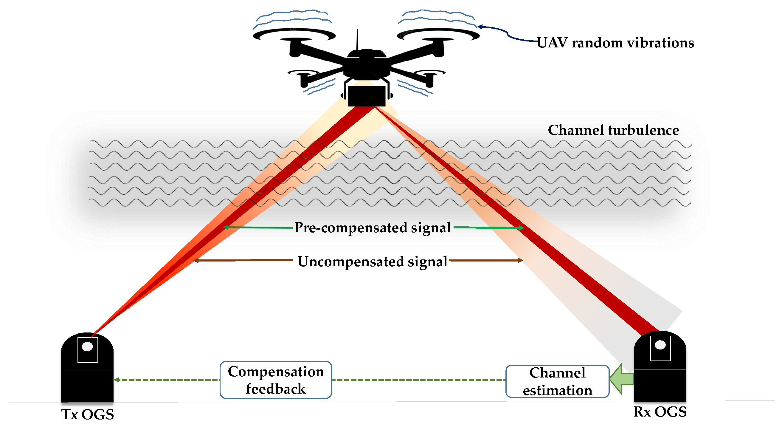
Optical power control: Another potential solution is to employ optical power control to provide power level compensation at the transmitter or the receiver terminals. Implementing this solution at the receiver terminal implies boosting the power levels using optical amplifiers such as an Erbium-Doped Fiber Amplifier (EDFA) to compensate for power losses from the atmosphere, while implementing power control at the transmitter side is based on pre-compensation of predicted signal attenuation from the channel. Both architectures aim to ensure that the power levels do not fall below acceptable threshold values.
(iii)
Adaptive optics: Another solution that has been frequently exploited for point-to-point FSO links is to employ adaptive optics techniques that utilize real-time feedback to dynamically correct distortions to the beam. This includes using wavefront sensors and deformable mirror modules like SLM to compensate for aberrations to the wavefront.
(iv)
Adaptive signal modulation: A promising solution is found in advanced methods such as adaptive modulation schemes, which have been shown to improve transmission capacity by adapting the modulation scheme based on the channel’s conditions. Although adaptive modulation has been explored for terrestrial experiments, implementing it in a UAV-relay scenario to compensate for atmospheric losses is a solution to be explored. Also, robust modulation schemes like Trellis-Coded Modulation (TCM) and Orthogonal Frequency-Division Multiplexing (OFDM) help combat fading and errors caused by turbulence.
(v)
Hybrid RF-FSO: Furthermore, a solution can be found in adopting a hybrid RF-FSO communication method that allows switching between optical and RF links or simultaneous operation. This provides communication redundancy and flexibility to accommodate impairments from unfavorable atmospheric conditions and ensure link reliability. However, challenges such as data rate mismatch and optimal signaling and routing need to be addressed [76].
(vi)
Spatial diversity: Diversity techniques at the transmitter and receiver terminals involve utilizing multiple parallel optical paths or multiple receiver apertures to mitigate the impact of a turbulent channel. By combining the signals received from different paths or apertures, the effects of turbulence can be mitigated. Implementing such techniques in a UAV-enabled relay scenario, possibly with a UAV swarm of multiple relays, could be worth exploring as a possible solution.
(vii)
Improved fiber coupling: Several UAV relay scenarios adopt photodetector-based receivers. However, high-rate communication methods, such as coherent communications capable of hundreds of Gbps up to multi-Tbps, utilize optical collimator heads that focus the beam into a coupled fiber and thus are sensitive to geometric alignment between the beam wavefront and the fiber interface. Hence, a tight fiber coupling is required to eliminate losses from distorted beam angles. Also, special fibers with larger core diameters might be utilized to accommodate the received beam even at its distorted angle.
Although the identified solutions apply to terrestrial point-to-point FSO transmission scenarios, they are also suited to UAV relay systems. However, owing to the contributions of the UAV, the degree of precision of such methods is subject to experimental validation in future work.

7.4. Pointing and Tracking

The key challenges in the PAT of a UAV-enabled relay system stem from the dynamic nature of the aerial platform, allied with the tight requirements of an FSO link. The exploration of actuation mechanisms and customizations for UAV payloads, which can compensate for pointing errors, is restricted by strict SWaP constraints. Additionally, low tracking speeds and tracking lag in PAT systems make it difficult to maintain link alignment between the OGS and UAVs during high-speed and large-scale motions, potentially leading to communication disruptions. To address these issues, agile PAT solutions are required that enable rapid signal acquisition or re-acquisition to restore the link quickly and incorporate redundancies to minimize disruptions. The suggested solutions are adapted from terrestrial point-to-point configurations to accommodate the contributions of UAV platforms.
(i)
Vibration-aware PAT: The unique vibrations experienced by UAVs require solutions that accommodate high-frequency motion to cancel them out effectively. One solution to mitigate beam misalignment by platform vibrations is the use of active UAV payloads such as FSMs, coupled with stabilization mechanisms. These payloads provide UAV beam steering and vibration compensation to minimize misalignments and assist in PAT operations while offering higher control freedom and increased FOV. However, to address SWaP constraints, compact modules such as MEMS FSMs can be utilized.
(ii)
Hybrid RF-FSO: Another solution is the implementation of a hybrid RF-FSO system that can switch between FSO and RF methods if the optical signal is lost due to misalignment, allowing for signal re-acquisition. The constant RF feedback ensures quick reacquisition of the UAV terminal, especially during large-scale motion. Additionally, the RF component serves as a backup link during communication disruptions.
(iii)
Receiver aperture: Increasing the number of receiver apertures on the ground can help reduce PAT requirements. Photodiode receivers are more resilient to pointing errors or offsets, and they offer potentially larger aperture sizes as well as the option of an array of multiple receivers that can capture the FSO beam. However, a wider aperture implies that there may be a trade-off between aperture size and achievable data rate.
(iv)
Adaptive optics methods: Coherent communication paradigms that employ optical-to-fiber collimators require strict placement of the beam into the fiber core. In such setups, adaptive methods, such as using SLMs, can be employed to fine-tune the received beam’s position.
Overall, the scarcity of research efforts dedicated to enhancing PAT performance in UAV-enabled FSO relay systems and the integration and synchronization between OGS and aerial platform modules pose hurdles to effectively streamlining the system’s functionality.

7.5. Intelligent Methodologies

Recent advances in ML and Artificial Intelligence (AI) can be leveraged in UAV-enabled relay systems to enhance their operations in dynamic environments by being adaptable to varying atmospheric conditions, moving targets, or unforeseen sources of communication disruption. A lack of intelligence implies the system may struggle to proactively adjust parameters, resulting in sub-optimal performance. Therefore, intelligent methods and algorithms can learn from historical data and recorded system performance metrics to identify optimal parameters to enhance efficiency and performance. For example, in the area of power management, battery power can be optimized by considering performance objectives, operational profiles, and energy constraints to dynamically allocate power resources among modules and components. This enables efficient power usage, extending the flight time/operational duration of the UAV and maximizing the performance of the FSO relay system. This is also important for determining optimal flight trajectories and flight profiles that can also evade obstacles and reduce power consumption during flight.
Furthermore, by analyzing system data and patterns, intelligent methods can identify potential faults, anomalies, or performance degradation. This enables proactive/predictive robust fault detection and recovery capabilities. Also, to exploit active payloads, intelligent methods can optimize the beam steering process to dynamically adjust the beam pointing direction for optimal signal strength and link quality between the UAV and the OGS. This ensures that the FSO relay system maintains a reliable and efficient connection. Moreover, to maintain high data rates, intelligent methods can dynamically adapt the modulation and coding schemes based on real-time channel conditions and link quality to ensure that the FSO relay system achieves the highest possible data rate while maintaining reliable communication under varying atmospheric conditions [71]. Finally, machine learning-enabled object identification and tracking is a method already investigated by [50] as a way to enhance PAT and is another example that validates the need for intelligent methodologies in UAV-enabled FSO relay systems.
Due to the combined effects of UAV random motion and propeller airflow to turbulence, instead of adopting traditional statistical models for channel estimation, a good approach is to utilize ML methods based on growing UAV-based FSO communication datasets to model the unique impairments, which could foster better data-driven forecasting/compensation. Similarly, intelligent methods could incorporate ML-based visual tracking of UAVs, which could be a suitable contribution to tracking the large-scale motion of UAVs by exploiting object identification and tracking models as well as flight path prediction algorithms. However, care must be taken when tracking platforms in high-speed motion since larger corrections are needed, especially during abrupt deceleration at flight boundaries.

7.6. Security and Safety

Given their narrow beam width, electromagnetic neutrality, and their point-to-point transmission, security and data privacy are intrinsic to FSO transmissions. However, in the case of operational networks where a variable number of UAVs work with other communication systems, such as terrestrial networks or satellite links, the integration of handover mechanisms into the network may require security considerations such as robust encryption and authentication to protect data during handovers [77]. Furthermore, as more platforms are deployed into the next-generation 3D network, safety becomes more important and demands strict adherence to necessary flight regulations [78], with the possible need to acquire licenses and/or certificates that authorize flight operations within specified air spaces [16]. If not proactively addressed, such regulatory and compliance issues can pose a hurdle to prompt deployment logistics. Although such regulations are still maturing, it is important to stay up to date on their evolution. For example, several Canadian, U.S., and European organizations have been working to harmonize the regulatory approaches for flying platforms in their respective air spaces for commercial use, with a focus on the platforms equipped with risk management equipment, especially if the platforms operate beyond LOS and in populated urban areas [16]. Finally, risk factors to life and property must be given consideration; creating secure operations requires strategies to prevent collisions and implement emergency, failure, and recovery strategies while maintaining LOS integrity and preventing transmission outages. Obstacle avoidance offers well-researched solutions, with a range of flexible collision avoidance strategies [79,80] that should be considered along with optimal route planning.

8. Conclusions

Addressing the rapidly growing interest in 3D optical wireless communications, this paper provides a comprehensive review of UAV-assisted FSO relay systems. Special focus is given to commercially available free-flying platforms that are driving advancements in this domain, emphasizing their adaptability, affordability, operational flexibility, and scalability, which makes them the ideal tools for researchers to demonstrate experimental efforts and to extend the technologies necessary for the proliferation of UAV-enabled FSO communication architectures. To establish suitability for different use cases and performance requirements, we have categorized the different platforms based on operational altitudes and payload actuation capacity, highlighting design considerations for optimal performance in terms of communication throughput and other relevant metrics. After a review of efforts in this field, this study identifies gaps in current demonstrations and provides recommendations to bridge these gaps, serving as a reference guide for researchers involved in the development of UAV-enabled FSO relay systems. Overall, the paper serves as a valuable resource for researchers involved in the development of the next-generation 3D wireless network, enabling them to make informed decisions and pave the way for the successful implementation of UAV-enabled FSO relay systems [61].

Author Contributions

Conceptualization, N.J.N., M.A.F., F.P.G., and G.M.F.; methodology, N.J.N., M.A.F., F.P.G. and G.M.F.; software, N.J.N.; validation, N.J.N., M.A.F., P.P.M., F.P.G., and G.M.F.; formal analysis, N.J.N.; investigation, N.J.N.; resources, P.P.M. and F.P.G.; data curation, N.J.N.; writing—original draft preparation, N.J.N. and G.M.F.; writing—review and editing, N.J.N., M.A.F., P.P.M., F.P.G., and G.M.F.; visualization, N.J.N., M.A.F., F.P.G., and G.M.F.; supervision, M.A.F., P.P.M., F.P.G., and G.M.F.; project administration, P.P.M. and F.P.G.; funding acquisition, F.P.G. and P.P.M. All authors have read and agreed to the published version of the manuscript.

Funding

This work was partially supported by FEDER, through the CENTRO 2020 programme, project ORCIP (CENTRO-01-0145-FEDER-022141), the MSCA RISE programme through project DIOR (grant agreement no. 101008280), and by FCT/MCTES through project OptWire (PTDC/EEI-TEL/2697/2021). Gil M. Fernandes acknowledges a contract program from FCT with code 2022.07168.CEECIND.

Conflicts of Interest

The authors declare no conflicts of interest.

References

  1. Raghavan, V.; Li, J. Evolution of Physical-Layer Communications Research in the Post-5G Era. IEEE Access 2019, 7, 10392–10401. [Google Scholar] [CrossRef]
  2. Hamza, A.S.; Deogun, J.S.; Alexander, D.R. Classification Framework for Free Space Optical Communication Links and Systems. IEEE Commun. Surv. Tutor. 2019, 21, 1346–1382. [Google Scholar] [CrossRef]
  3. Rangan, S.; Rappaport, T.S.; Erkip, E. Millimeter Wave Cellular Wireless Networks: Potentials and Challenges. Proc. IEEE 2014, 102, 366–385. [Google Scholar] [CrossRef]
  4. Akyildiz, I.F.; Jornet, J.M.; Han, C. TeraNets: Ultra-Broadband Communication Networks in the Terahertz Band. IEEE Wirel. Commun. 2014, 21, 130–135. [Google Scholar] [CrossRef]
  5. Fernandes, M.A.; Monteiro, P.P.; Guiomar, F.P. Single-Wavelength Terabit FSO Channel for Datacenter Interconnects Enabled by Adaptive PCS. In Proceedings of the 2021 Optical Fiber Communications Conference and Exhibition (OFC), San Francisco, CA, USA, 6–10 June 2021; pp. 1–3. [Google Scholar]
  6. Sabri, A.A.; Hameed, S.M.; Hadi, W.A.H. Last Mile Access-Based FSO and VLC Systems. Appl. Opt. 2023, 62, 8402–8410. [Google Scholar] [CrossRef] [PubMed]
  7. An, N.; Yang, F.; Cheng, L.; Song, J.; Han, Z. Free Space Optical Communications for Intelligent Transportation Systems: Potentials and Challenges. IEEE Veh. Technol. Mag. 2023, 18, 80–90. [Google Scholar] [CrossRef]
  8. Chaudhry, A.U.; Yanikomeroglu, H. Free Space Optics for Next-Generation Satellite Networks. IEEE Consum. Electron. Mag. 2021, 10, 21–31. [Google Scholar] [CrossRef]
  9. Schieler, C.M.; Riesing, K.M.; Bilyeu, B.C.; Chang, J.S.; Garg, A.S.; Gilbert, N.C.; Horvath, A.J.; Reeve, R.S.; Robinson, B.S.; Wang, J.P.; et al. On-Orbit Demonstration of 200-Gbps Laser Communication Downlink from the TBIRD CubeSat. In Proceedings of the Free-Space Laser Communications XXXV, San Francisco, CA, USA, 28 January–3 February 2023; Hemmati, H., Robinson, B.S., Eds.; SPIE: Bellingham, WA, USA, 2023; p. 1. [Google Scholar] [CrossRef]
  10. Zeng, Y.; Zhang, R.; Lim, T.J. Wireless Communications with Unmanned Aerial Vehicles: Opportunities and Challenges. IEEE Commun. Mag. 2016, 54, 36–42. [Google Scholar] [CrossRef]
  11. Mozaffari, M.; Saad, W.; Bennis, M.; Nam, Y.H.; Debbah, M. A Tutorial on UAVs for Wireless Networks: Applications, Challenges, and Open Problems. IEEE Commun. Surv. Tutor. 2019, 21, 2334–2360. [Google Scholar] [CrossRef]
  12. Huo, Y.; Dong, X.; Lu, T.; Xu, W.; Yuen, M. Distributed and Multilayer UAV Networks for Next-Generation Wireless Communication and Power Transfer: A Feasibility Study. IEEE Internet Things J. 2019, 6, 7103–7115. [Google Scholar] [CrossRef]
  13. Li, B.; Fei, Z.; Zhang, Y. UAV Communications for 5G and Beyond: Recent Advances and Future Trends. IEEE Internet Things J. 2019, 6, 2241–2263. [Google Scholar] [CrossRef]
  14. Chen, J.; Zhang, H.; Xie, Z. Space-Air-Ground Integrated Network (SAGIN): A Survey. IEEE Commun. Surv.Tutor. 2023, 20, 2714–2741. [Google Scholar] [CrossRef]
  15. Alimi, I.A.; Mufutau, A.O.; Teixeira, A.L.; Monteiro, P.P. Performance Analysis of Space-Air-Ground Integrated Network (SAGIN) Over an Arbitrarily Correlated Multivariate FSO Channel. Wirel. Pers. Commun. 2018, 100, 47–66. [Google Scholar] [CrossRef]
  16. Alzenad, M.; Shakir, M.Z.; Yanikomeroglu, H.; Alouini, M.S. FSO-Based Vertical Backhaul/Fronthaul Framework for 5G+ Wireless Networks. IEEE Commun. Mag. 2018, 56, 218–224. [Google Scholar] [CrossRef]
  17. Majumdar, A.K. Free-Space Optical (FSO) Platforms: Unmanned Aerial Vehicle (UAV) and Mobile. In Advanced Free Space Optics (FSO): A Systems Approach; Majumdar, A.K., Ed.; Springer Series in Optical Sciences; Springer: New York, NY, USA, 2015; pp. 203–225. [Google Scholar] [CrossRef]
  18. Han, B.; Jiang, W.; Habibi, M.A.; Schotten, H.D. An Abstracted Survey on 6G: Drivers, Requirements, Efforts, and Enablers. arXiv 2021, arXiv:2101.01062. [Google Scholar]
  19. Akhtar, M.W.; Hassan, S.A.; Ghaffar, R.; Jung, H.; Garg, S.; Hossain, M.S. The Shift to 6G Communications: Vision and Requirements. Hum.-Centric Comput. Inf. Sci. 2020, 10, 53. [Google Scholar] [CrossRef]
  20. Belmekki, B.E.Y.; Alouini, M.S. Unleashing the Potential of Networked Tethered Flying Platforms: Prospects, Challenges, and Applications. IEEE Open J. Veh. Technol. 2022, 3, 278–320. [Google Scholar] [CrossRef]
  21. Ghamari, M.; Rangel, P.; Mehrubeoglu, M.; Tewolde, G.S.; Sherratt, R.S. Unmanned Aerial Vehicle Communications for Civil Applications: A Review. IEEE Access 2022, 10, 102492–102531. [Google Scholar] [CrossRef]
  22. Levitate Capital. The Future of the Drone Economy. Levitate Capital Technical Report. 2020. Available online: https://levitatecap.com/levitate/wp-content/uploads/2020/12/Levitate-Capital-White-Paper.pdf (accessed on 6 December 2023).
  23. Quintana, C.; Wang, Q.; Jakonis, D.; Oberg, O.; Erry, G.; Platt, D.; Thueux, Y.; Faulkner, G.; Chun, H.; Gomez, A.; et al. A High Speed Retro-Reflective Free Space Optics Links with UAV. J. Light. Technol. 2021, 39, 5699–5705. [Google Scholar] [CrossRef]
  24. Li, L.; Zhang, R.; Zhao, Z.; Xie, G.; Liao, P.; Pang, K.; Song, H.; Liu, C.; Ren, Y.; Labroille, G.; et al. High-Capacity Free-Space Optical Communications between a Ground Transmitter and a Ground Receiver via a UAV Using Multiplexing of Multiple Orbital-Angular-Momentum Beams. Sci. Rep. 2017, 7, 17427. [Google Scholar] [CrossRef]
  25. Moision, B.; Erkmen, B.; Keyes, E.; Belt, T.; Bowen, O.; Brinkley, D.; Csonka, P.; Eglington, M.; Kazmierski, A.; Kim, N.h.; et al. Demonstration of Free-Space Optical Communication for Long-Range Data Links between Balloons on Project Loon. In Proceedings of the Free-Space Laser Communication and Atmospheric Propagation XXIX, San Francisco, CA, USA, 28 January–2 February 2017; SPIE: Bellingham, WA, USA, 2017; Volume 10096, pp. 259–272. [Google Scholar] [CrossRef]
  26. Horwath, J.; Perlot, N.; Knapek, M.; Moll, F. Experimental Verification of Optical Backhaul Links for High-Altitude Platform Networks: Atmospheric Turbulence and Downlink Availability. Int. J. Satell. Commun. Netw. 2007, 25, 501–528. [Google Scholar] [CrossRef]
  27. Cunningham, J.; Foulke, D.; Goode, T.; Baber, D.; Gaughan, B.; Fletcher, M.; Young, D.W.; Juarez, J.C.; Sluz, J.E.; Riggins, J.L. Long Range Field Testing of Free Space Optical Communications Terminals on Mobile Platforms. In Proceedings of the MILCOM 2009—2009 IEEE Military Communications Conference, Boston, MA, USA, 18–21 October 2009; pp. 1–7. [Google Scholar] [CrossRef]
  28. Sova, R.M.; Sluz, J.E.; Young, D.W.; Juarez, J.C.; Dwivedi, A.; Iii, N.M.D.; Graves, J.E.; Northcott, M.; Douglass, J.; Phillips, J.; et al. 80 Gb/s Free-Space Optical Communication Demonstration between an Aerostat and a Ground Terminal. In Proceedings of the Free-Space Laser Communications VI, San Diego, CA, USA, 13–17 August 2006; SPIE: Bellingham, WA, USA, 2006; Volume 6304, pp. 267–276. [Google Scholar] [CrossRef]
  29. Yu, S.; Li, B.; Cao, K.; Hao, G.; Du, H. Design and Verification of Free Space Optical Communication Relay between Ground and Tethered Ball. Trans. Nanjing Univ. Aeronaut. Astronaut. 2023, 60–70. [Google Scholar] [CrossRef]
  30. Ishola, F.; Carrasco-Casado, A.; Dimitar, K.; Trinh, P.; Shiratama, K.; Fuse, T.; Tsuji, H.; Toyoshima, M. Development of Tethered Unmanned Aerial Vehicle Laser Communication Station for Beyond-5G Applications; International Astronautical Federation: Paris, France, 2022. [Google Scholar]
  31. Goetz, P.G.; Rabinovich, W.S.; Mahon, R.; Murphy, J.L.; Ferraro, M.S.; Suite, M.R.; Smith, W.R.; Burris, H.R.; Moore, C.I.; Schultz, W.W.; et al. Modulating Retro-Reflector Lasercom Systems for Small Unmanned Vehicles. IEEE J. Sel. Areas Commun. 2012, 30, 986–992. [Google Scholar] [CrossRef]
  32. Shortt, K.; Giggenbach, D.; Mata-Calvo, R.; Moll, F.; Fuchs, C.; Schmidt, C.; Horwath, J.; Yeh, J.; Selvaraj, V.; Banerjee, R. Channel Characterization for Air-to-Ground Free-Space Optical Communication Links. In Proceedings of the Free-Space Laser Communication and Atmospheric Propagation XXVI, San Francisco, CA, USA, 1–6 February 2014; SPIE: Bellingham, WA, USA, 2014; Volume 8971, pp. 68–80. [Google Scholar] [CrossRef]
  33. Chen, C.; Grier, A.; Malfa, M.; Booen, E.; Harding, H.; Xia, C.; Hunwardsen, M.; Demers, J.; Kudinov, K.; Mak, G.; et al. Demonstration of a Bidirectional Coherent Air-to-Ground Optical Link. In Proceedings of the Free-Space Laser Communication and Atmospheric Propagation XXX, San Francisco, CA, USA, 27 January–1 February 2018; SPIE: Bellingham, WA, USA, 2018; Volume 10524, pp. 120–134. [Google Scholar] [CrossRef]
  34. Quintana, C.; Erry, G.; Gomez, A.; Thueux, Y.; Faulkner, G.E.; O’Brien, D.C. Design of a Holographic Tracking Module for Long-Range Retroreflector Free-Space Systems. Appl. Opt. 2016, 55, 7173–7178. [Google Scholar] [CrossRef] [PubMed]
  35. Trinh, P.V.; Carrasco-Casado, A.; Okura, T.; Tsuji, H.; Kolev, D.R.; Shiratama, K.; Munemasa, Y.; Toyoshima, M. Experimental Channel Statistics of Drone-to-Ground Retro-Reflected FSO Links with Fine-Tracking Systems. IEEE Access 2021, 9, 137148–137164. [Google Scholar] [CrossRef]
  36. Liu, H.Y.; Tian, X.H.; Gu, C.; Fan, P.; Ni, X.; Yang, R.; Zhang, J.N.; Hu, M.; Guo, J.; Cao, X.; et al. Drone-Based Entanglement Distribution towards Mobile Quantum Networks. Natl. Sci. Rev. 2020, 7, 921–928. [Google Scholar] [CrossRef]
  37. Walsh, S.M.; Karpathakis, S.F.E.; McCann, A.S.; Dix-Matthews, B.P.; Frost, A.M.; Gozzard, D.R.; Gravestock, C.T.; Schediwy, S.W. Demonstration of 100 Gbps Coherent Free-Space Optical Communications at LEO Tracking Rates. Sci. Rep. 2022, 12, 18345. [Google Scholar] [CrossRef] [PubMed]
  38. Thueux, Y.; Avlonitis, N.; Erry, G. DAZZLE Project: UAV to Ground Communication System Using a Laser and a Modulated Retro-Reflector. In Proceedings of the SPIE SECURITY + DEFENCE, Amsterdam, The Netherlands, 22–25 September 2014; Volume 9248. [Google Scholar] [CrossRef]
  39. Tu, C.; Shen, J.; Dai, J.; Zhang, L.; Wang, J. A Lower Size, Weight Acquisition and Tracking System for Airborne Quantum Communication. IEEE Photonics J. 2022, 14, 7356908. [Google Scholar] [CrossRef]
  40. Qi, W.; Hou, W.; Song, Q.; Guo, L.; Jamalipour, A. Topology Control and Routing Based on Adaptive RF/FSO Switching in Space-Air Integrated Networks. In Proceedings of the 2016 IEEE Global Communications Conference (GLOBECOM), Washington, DC, USA, 4–8 December 2016; pp. 1–6. [Google Scholar] [CrossRef]
  41. Zhang, N.; Zhang, S.; Yang, P.; Alhussein, O.; Zhuang, W.; Shen, X.S. Software Defined Space-Air-Ground Integrated Vehicular Networks: Challenges and Solutions. IEEE Commun. Mag. 2017, 55, 101–109. [Google Scholar] [CrossRef]
  42. Horwath, J.; Gonzalez, D.D.; Navajas, L.M.; Souto, A.L.; Semerjyan, V.; Raju, G.; Grabowsky, J.; Garcia, C.; Lai, Y.; Bähr, T.; et al. Test Results of Error-Free Bidirectional 10 Gbps Link for Air-to-Ground Optical Communications. In Proceedings of the Free-Space Laser Communication and Atmospheric Propagation XXX, San Francisco, CA, USA, 27 January–1 February 2018; SPIE: Bellingham, WA, USA, 2018; Volume 10524, pp. 417–430. [Google Scholar] [CrossRef]
  43. Cui, J.; Ng, S.X.; Liu, D.; Zhang, J.; Nallanathan, A.; Hanzo, L. Multiobjective Optimization for Integrated Ground-Air-Space Networks: Current Research and Future Challenges. IEEE Veh. Technol. Mag. 2021, 16, 88–98. [Google Scholar] [CrossRef]
  44. Han, S.I. Survey on UAV Deployment and Trajectory in Wireless Communication Networks: Applications and Challenges. Information 2022, 13, 389. [Google Scholar] [CrossRef]
  45. Tethered Aerostats—TCOM. Available online: https://tcomlp.com/aerospace-platforms/tethered-aerostats/ (accessed on 4 January 2024).
  46. Kishk, M.; Bader, A.; Alouini, M.S. Aerial Base Station Deployment in 6G Cellular Networks Using Tethered Drones: The Mobility and Endurance Tradeoff. IEEE Veh. Technol. Mag. 2020, 15, 103–111. [Google Scholar] [CrossRef]
  47. European Union Law. Commission Implementing Regulation (EU) 2019/947 of 24 May 2019 on the Rules and Procedures for the Operation of Unmanned Aircraft (Text with EEA Relevance). Available online: https://eur-lex.europa.eu/eli/reg_impl/2019/947/oj/eng (accessed on 12 December 2023).
  48. Spreading Wings S900—DJI. Available online: https://www.dji.com/pt/spreading-wings-s900 (accessed on 4 January 2024).
  49. Abdelfatah, R.; Alshaer, N.; Ismail, T. A Review on Pointing, Acquisition, and Tracking Approaches in UAV-based Fso Communication Systems. Opt. Quantum Electron. 2022, 54, 571. [Google Scholar] [CrossRef]
  50. Isaac-Medina, B.K.S.; Poyser, M.; Organisciak, D.; Willcocks, C.G.; Breckon, T.P.; Shum, H.P.H. Unmanned Aerial Vehicle Visual Detection and Tracking Using Deep Neural Networks: A Performance Benchmark. In Proceedings of the 2021 IEEE/CVF International Conference on Computer Vision Workshops (ICCVW), Montreal, QC, Canada, 11–17 October 2021. [Google Scholar] [CrossRef]
  51. Kasturi, A.; Milanovic, V.; Atwood, B.H.; Yang, J. UAV-borne Lidar with MEMS Mirror-Based Scanning Capability. In Proceedings of the SPIE Defense + Security, Baltimore, MD, USA, 17–21 April 2016; Turner, M.D., Kamerman, G.W., Eds.; SPIE: Bellingham, WA, USA, 2016; p. 98320M. [Google Scholar] [CrossRef]
  52. Abadi, M.M.; Cox, M.A.; Alsaigh, R.E.; Viola, S.; Forbes, A.; Lavery, M.P.J. A Space Division Multiplexed Free-Space-Optical Communication System That Can Auto-Locate and Fully Self Align with a Remote Transceiver. Sci. Rep. 2019, 9, 19687. [Google Scholar] [CrossRef]
  53. Safi, H.; Dargahi, A.; Cheng, J. Beam Tracking for UAV-Assisted FSO Links with a Four-Quadrant Detector. IEEE Commun. Lett. 2021, 25, 3908–3912. [Google Scholar] [CrossRef]
  54. Dabiri, M.T.; Rezaee, M.; Mohammadi, L.; Javaherian, F.; Yazdanian, V.; Hasna, M.O.; Uysal, M. Modulating Retroreflector Based Free Space Optical Link for UAV-to-Ground Communications. IEEE Trans. Wirel. Commun. 2022, 21, 8631–8645. [Google Scholar] [CrossRef]
  55. MEETOPTICS. Retroreflectors, Corner Cube Reflectors. Available online: https://bitly.ws/3fndd (accessed on 5 March 2024).
  56. Ishola, F.; Cho, M. Experimental Study on Photodiode Array Sensor Aided MEMS Fine Steering Mirror Control for Laser Communication Platforms. IEEE Access 2021, 9, 100197–100207. [Google Scholar] [CrossRef]
  57. Fast Steering Mirrors. Available online: https://www.optotune.com/fast-steering-mirrors (accessed on 5 March 2024).
  58. S-340 Piezo Tip/Tilt Platform. Available online: https://bitly.ws/3fnhL (accessed on 4 March 2024).
  59. Mirrorcle MEMS Mirrors—Technical Overview. 2021. Available online: https://bitly.ws/3fnbt (accessed on 5 March 2024).
  60. Integrated Mirrors. 2024. Available online: https://www.mirrorcletech.com/wp/products/mems-mirrors/dual/integrated/ (accessed on 5 March 2024).
  61. Electromagentically Driven MEMS Mirrors. 2021. Available online: https://www.hamamatsu.com/eu/en/product/optical-components/mems-mirror.html (accessed on 5 March 2023).
  62. Cui, M.; Zhang, G.; Zhang, R. Secure Wireless Communication via Intelligent Reflecting Surface. IEEE Wirel. Commun. Lett. 2019, 8, 1410–1414. [Google Scholar] [CrossRef]
  63. Mohsan, S.A.H.; Khan, M.A.; Alsharif, M.H.; Uthansakul, P.; Solyman, A.A.A. Intelligent Reflecting Surfaces Assisted UAV Communications for Massive Networks: Current Trends, Challenges, and Research Directions. Sensors 2022, 22, 5278. [Google Scholar] [CrossRef]
  64. Malik, S.; Saxena, P.; Chung, Y.H. Performance Analysis of a UAV-based IRS-assisted Hybrid RF/FSO Link with Pointing and Phase Shift Errors. J. Opt. Commun. Netw. 2022, 14, 303–315. [Google Scholar] [CrossRef]
  65. Safi, H.; Dargahi, A.; Cheng, J. Spatial Beam Tracking and Data Detection for an FSO Link to a UAV in the Presence of Hovering Fluctuations. arXiv 2019, arXiv:1904.03774. [Google Scholar] [CrossRef]
  66. Jebur, B.A.; Alkassar, S.H.; Abdullah, M.A.M.; Tsimenidis, C.C. Efficient Machine Learning-Enhanced Channel Estimation for OFDM Systems. IEEE Access 2021, 9, 100839–100850. [Google Scholar] [CrossRef]
  67. Mishra, P.; Sonali; Dixit, A.; Jain, V.K. Machine Learning Techniques for Channel Estimation in Free Space Optical Communication Systems. In Proceedings of the 2019 IEEE International Conference on Advanced Networks and Telecommunications Systems (ANTS), Goa, India, 16–19 December 2019; pp. 1–6. [Google Scholar] [CrossRef]
  68. Esmail, M.A.; Saif, W.S.; Ragheb, A.M.; Alshebeili, S.A. Free Space Optic Channel Monitoring Using Machine Learning. Opt. Express 2021, 29, 10967–10981. [Google Scholar] [CrossRef] [PubMed]
  69. Li, J.; Zhang, M.; Wang, D.; Wu, S.; Zhan, Y. Joint Atmospheric Turbulence Detection and Adaptive Demodulation Technique Using the CNN for the OAM-FSO Communication. Opt. Express 2018, 26, 10494–10508. [Google Scholar] [CrossRef] [PubMed]
  70. Lionis, A.; Peppas, K.; Nistazakis, H.E.; Tsigopoulos, A.; Cohn, K.; Zagouras, A. Using Machine Learning Algorithms for Accurate Received Optical Power Prediction of an FSO Link over a Maritime Environment. Photonics 2021, 8, 212. [Google Scholar] [CrossRef]
  71. Fernandes, M.A.; Nascimento, J.L.; Monteiro, P.P.; Guiomar, F.P. Highly Reliable Outdoor 400G FSO Transmission Enabled by ANN Channel Estimation. In Proceedings of the 2022 Optical Fiber Communications Conference and Exhibition (OFC), San Diego, CA, USA, 6–10 March 2022; pp. 1–3. [Google Scholar]
  72. Cai, C.; Wu, S.; Jiang, L.; Zhang, Z.; Yang, S. A 500-W Wireless Charging System with Lightweight Pick-Up for Unmanned Aerial Vehicles. IEEE Trans. Power Electron. 2020, 35, 7721–7724. [Google Scholar] [CrossRef]
  73. Shin, M.; Kim, J.; Levorato, M. Auction-Based Charging Scheduling with Deep Learning Framework for Multi-Drone Networks. IEEE Trans. Veh. Technol. 2019, 68, 4235–4248. [Google Scholar] [CrossRef]
  74. Carrasco-Casado, A.; Shiratama, K.; Trinh, P.V.; Kolev, D.; Ishola, F.; Fuse, T.; Tsuji, H.; Toyoshima, M. NICT’s Versatile Miniaturized Lasercom Terminals for Moving Platforms. In Proceedings of the 2022 IEEE International Conference on Space Optical Systems and Applications (ICSOS), Kyoto City, Japan, 28–31 March 2022; pp. 213–217. [Google Scholar] [CrossRef]
  75. Barrios, R.; Dios, F. Wireless Optical Communications Through the Turbulent Atmosphere: A Review. In Optical Communications Systems; Das, N., Ed.; IntechOpen: Rijeka, Croatia, 2012. [Google Scholar] [CrossRef]
  76. Khalighi, M.A.; Uysal, M. Survey on Free Space Optical Communication: A Communication Theory Perspective. IEEE Commun. Surv. Tutor. 2014, 16, 2231–2258. [Google Scholar] [CrossRef]
  77. Khalid, H.; Hashim, S.J.; Hashim, F.; Ahamed, S.M.S.; Chaudhary, M.A.; Altarturi, H.H.M.; Saadoon, M. HOOPOE: High Performance and Efficient Anonymous Handover Authentication Protocol for Flying Out of Zone UAVs. IEEE Trans. Veh. Technol. 2023, 72, 10906–10920. [Google Scholar] [CrossRef]
  78. Elamassie, M.; Uysal, M. Free Space Optical Communication: An Enabling Backhaul Technology for 6G Non-Terrestrial Networks. Photonics 2023, 10, 1210. [Google Scholar] [CrossRef]
  79. Seo, J.; Kim, Y.; Kim, S.; Tsourdos, A. Collision Avoidance Strategies for Unmanned Aerial Vehicles in Formation Flight. IEEE Trans. Aerosp. Electron. Syst. 2017, 53, 2718–2734. [Google Scholar] [CrossRef]
  80. Zhu, X.; Liang, Y.; Yan, M. A Flexible Collision Avoidance Strategy for the Formation of Multiple Unmanned Aerial Vehicles. IEEE Access 2019, 7, 140743–140754. [Google Scholar] [CrossRef]
Figure 1. Application of UAV-enabled 3D relay across several scenarios.
Photonics 11 00274 g001
Figure 2. Qualitative comparison of key performance indicators of different UAV platforms.
Photonics 11 00274 g002
Figure 3. Coarse and fine-pointing sequence summary with key OGS and UAV components utilized.
Photonics 11 00274 g003
Figure 4. Active payload relay capable of steering to separated OGSs compared to a passive payload that can relay to originating co-located OGS.
Photonics 11 00274 g004
Figure 5. An integrated stabilization gimbal and steering mirror concept providing enhanced PAT accuracy/stability and wider FOV.
Photonics 11 00274 g005
Figure 6. FSO signal impairment contributions primarily from channel atmospheric turbulence and UAV, as well as the computed pre-compensation to maintain signal fidelity.
Photonics 11 00274 g006
Table 1. Classification and a brief description of aerial platform types according to operational altitudes.
ClassPlatform TypeAltitudeDescription
HAPAerostatPhotonics 11 00274 i00117 km–22 kmLonger endurance vehicles, typically buoyant aerostats, operating in the stratosphere, thereby having a wide field of view, and with a large lift capacity to accommodate a range of communication apparatus.
LAPTethered AerostatPhotonics 11 00274 i002300 m–10 km   More compact and streamlined form, capable of operating within the troposphere. It is usually tethered to the ground, allowing long-duration operations but a with limited range of motion. 
Fixed-wing free-flyingPhotonics 11 00274 i00330 m–10 kmFixed-wing platforms are characterized by propellers and wings that provide horizontal take-off. They are capable of tropospheric flight, and the hybrid variants with multiple rotors and wings are capable of minimal hovering in operation. 
Multi-rotor free-flyingPhotonics 11 00274 i00430 m–120 mMulti-rotor platforms are cost-effective platforms operating within regulated altitudes, capable of vertical take-off, with hover capabilities and agile flight over every degree of freedom.
Table 2. Platform classification and a short description of reviewed FSO demonstrations employing either HAP or LAP platforms.
ClassificationSourceDemonstrationAltitude
HAPs
Aerostat[25]Launched a pair of balloons that utilize long-range FSO links to augment terrestrial cellular networks with LTE wireless internet connectivity.20 km
[26]Deployed a stratospheric balloon to study the turbulence effect of FSO communications at higher altitudes.22 km
Winged/Free-flying[27]Verified the FSO terminal’s PAT operations using a 2.5 Gbps bidirectional link.
LAPs
TetheredAerostat[28]Demonstrated a high-bandwidth UAV-ground FSO link that used a WDM communications technique.1 km
[29]Validated a scanning acquisition scheme that compensates for the platform’s rapid altitude oscillations.1 km
Multi-rotor[30]Demonstrated the viability of a tethered multi-rotor to relay 10 Gbps full-duplex Ethernet connectivity over a 30 km range for an extended duration due to the tether power supply.100 m
Free-flyingWinged[31]Interrogated an array of corner-cube MRR pods installed on the wings of a fixed-wing platform using ground-based transmitter and receiver FSO terminal.
[32]Characterized air-to-ground FSO channels and compared results with theoretical models to identify requirements for future adaptive optics.2 km
[33]Demonstrated a bidirectional optical link transmitting 100 Gbps signals.5.3 km
Multi-rotor[34]Demonstrated visual-based PAT for a multiple quantum well MRR-mounted UAV relaying a 2 Mbps optical link to ground from 300 m.<120 m
[23]Demonstrated a novel EAM-based MRR mounted on a UAV to relay 500 Mbps FSO signals to OGS at 560 m range.<120 m
[35]Investigated the physical channel characteristics of a retro-reflected signal from a commercial multi-rotor UAV that combines channel impairments with random trajectories from the drone’s hovering.15–20 m
[24]Demonstrated the relay of an 80 Gbps FSO signal with two multiplexed OAM modes between Tx and Rx OGS via a UAV-mounted retro-reflector.20 m
[36]Demonstrated a mobile entanglement distribution between two ground stations at a 200 m separation using a UAV-mounted entangle-photon source.
[37]Demonstrated the ability to sustain a relay link between an OGS and a UAV at a horizontal flight speed of 60 km/h.120 m
[35]Investigated the underlying physical channel effects of aerial retro-reflected FSO signals due to the combination of channel effects and the UAV’s hovering random trajectories that result in AoA fluctuations.20 m
[38]Tested of a UAV-mounted MRR module capable of 20 Mbps relay over ranges of 75 m, 500 m, and 1200 m separation to determine its performance by measuring the BER.25 m
[39]Tested a quantum key distribution link between UAV and OGS at 7 km separation, thereby validating a customized low-SWaP payload prototype that integrates a steerable mirror & quantum key distribution hardware.<120 m
Table 3. Classification of demonstrated payloads according to active or passive functionality.
Payload TypeSourceAltitudePayload OperationPayload Weight
Active[25]20 kmLoon FSO communication terminal<50 kg
[26]22 kmLaser + beacon terminal17.54 kg
[33]5.3 kmCoherent transceiver (Telescope + PAT gimbal)≈10 kg
[27]Gimbal + FSO Tx/Rx optics + beacon laser modules
[28]1 kmWDM optical transmitter terminal with PAT + tip/tilt mirror20.5 kg
[29]1 kmLaser-generating terminal + IR camera + PAT<15 kg
[32]2 km1 Gps transmitter, telescope, PAT terminal
[36]A pair of Airborne Entangle Photon Sources (AEPSs) + PAT486 g (×2)
[39]<120 mSteering mirror, camera, quantum source8 kg
[30]100 m10 Gb Ethernet lasercom terminal + optical segment + MEMS FSM<4.5 kg
Passive[31]<120 mCorner-cube MRR array pods3.6 kg
[34]<120 mMQW-based MRR200 g
[23]<120 mEAM-based MRR
[24]20 mRetro-reflector module
[37]120 mGimbal-mounted CCR + beacon LEDs + camera
[35]20 mCCR module + alignment camera
[38]25 mMRR module200 g
[35]15–20 mCorner-cube reflector + camera<4.5 kg
Table 4. Key design requirements and considerations for a UAV-enabled FSO relay system.
Design RequirementsConsiderations
Stability & controlThe UAV should adopt a stabilization module that can counteract the vibrations inherent to propulsion components.
The module should have a wide angular range and accurate pointing resolution to complement OGS PAT during hover, vertical, and horizontal flight, and also compensate for UAV heading deviations from wind buffeting or random flight variables.
The module should cater to the specific payload’s mass, dimension, power, and extension port implications and must protect the payload against impact.
PayloadOwing to a tight SWaP constraint, the need for a passive or active payload module should be clearly determined.
The symmetry of the payload’s reflective surfaces must be flawless in order not to contribute to angular offsets on the relayed signal.
The UAV’s allowable payload capacity must be sufficient to accommodate equipment and modules required for the communication system’s operation while maintaining stable and controllable flight.
Modularity & scalabilityThe system should be designed in a modular fashion that allows easy replacement or addition of payload, equipment, or sensors, to adapt to changing mission needs.
Consider the addition of redundant modules to increase reliability during flight/communications relay operations.
The platform should be compatible with customization and open-source modules that can extend the platform’s performance range, allowing longer duration communication demonstrations and a wider range of experiments.
Safety and reliabilityConduct a risk analysis to determine potential risk factors and consider collision detection and avoidance units to limit possible accidents with property or even humans.
Conduct extensive tests and verification of customized or experimental modules on the ground before conducting flight operations.
Consider fault tolerance to prevent single-point failures by incorporating redundant power and navigation modules and implement failure recovery protocols such as emergency landing modes.
Implement adaptive and recovery techniques to prevent or recover from disruption to the FSO link, respectively.
Communication range & bandwidthThe UAV must have a constant and reliable RF communication link within the specified operational range to transmit flight control and commands, as well as feedback information, including GPS location/orientation, telemetry, and health status, all without interference from ambient signals.
The communication range must remain within regulated separation distance and operational altitudes at the chosen (non-segregated) flight location.
Ease of use & maintenanceThe UAV system must strive for a low-complexity design, with an intuitive, user-friendly interface that does not require an expert skill set, thus ensuring that the focus remains on the FSO communication relay mission.
Consider adopting an open-source approach that caters to vast commercial modules that can be integrated to ensure easy system modification and maintenance.
CostConsider cost-effective commercial multi-rotor platforms that allow for upgrades and customization. Moreover, if the UAV is damaged beyond recovery, commercial platforms can be replaced to ensure the continuity of the relay project.
The cost-effectiveness of commercial platforms encourages the inclusion of extra platform nodes, allowing the system to be scaled up to an FSO relay network or swarm.
SWaPConduct power/mass budget analysis to cater to the payload’s requirements and optimize the allocation to fit within the platform’s constraints.
Utilize miniaturized and lightweight components such as MEMS to maximize payload capacity and overall platform performance.
Implement power management techniques to optimize power distribution and conservation. Consider alternatives like a power tether to increase operational time.
Disclaimer/Publisher’s Note: The statements, opinions and data contained in all publications are solely those of the individual author(s) and contributor(s) and not of MDPI and/or the editor(s). MDPI and/or the editor(s) disclaim responsibility for any injury to people or property resulting from any ideas, methods, instructions or products referred to in the content.

