Article

Optimizing Self-Seeded Perfluorooctane SBS Compressor Configurations to Achieve ~90 ps High-Energy Pulses

by
Aleksej M. Rodin
*,
Augustė Černeckytė
,
Paulius Mackonis
and
Augustinas Petrulėnas
Solid State Laser Laboratory, Department of Laser Technologies, Center for Physical Sciences and Technology, Savanoriu 231, LT-02300 Vilnius, Lithuania
*
Author to whom correspondence should be addressed.
Photonics 2023, 10(9), 1060; https://doi.org/10.3390/photonics10091060
Submission received: 21 August 2023 / Revised: 12 September 2023 / Accepted: 19 September 2023 / Published: 20 September 2023
(This article belongs to the Special Issue Photonics: Theory, Technologies and Applications)

Abstract

:
Three different stimulated Brillouin scattering (SBS) configurations in perfluorooctane were experimentally compared to achieve the ultimate compression of ~1.1 ns pulses from a commercially available Nd:YAG mini-laser. These schemes contained either a focusing lens and a plane feedback mirror, a spherical mirror, or variable pulse splitting to provide self-seeding of the SBS. In the optimal configuration with a focusing lens and return mirror, 93 ps pulses with an energy of 9.5 mJ were achieved at the output of the double-pass phase-conjugated Nd:YAG amplifier. The resulting diffraction-free, high-quality beams with M2~1.2 and excellent pointing stability are of practical interest for scientific, medical, and industrial applications.

1. Introduction

In recent decades, the demand for high-energy picosecond and femtosecond laser pulses has grown rapidly in a wide range of scientific and technological fields. In particular, picosecond pulses have prospects for use in laser ranging [1], processing [2], and medicine [3,4]. Developed methods for generating picosecond laser pulses are burdened by the difficulty of obtaining pulses shorter than ~0.3 ns with Q-switching [5] or output energy limited to the microjoule level for mode-locking [6]. However, micromachining with sub-ns pulses is susceptible to thermal damage and is slow over large areas at µJ energies. Although high-energy picosecond pulses can be obtained from a more expensive master oscillator power amplifier (MOPA), the quality of the output beam due to distortion in the amplifier [7,8] is often not suitable for laser cosmetology. Thus, the development of cost-effective, high-energy picosecond lasers with high beam quality remain a challenge. An alternative approach would then be pulse compression via stimulated Brillouin scattering (SBS) using low-cost nanosecond Q-switched lasers [8].
The key advantage of the SBS compressor is the generation of a time-reversed beam at the Stokes frequency due to the phase-conjugate SBS mirror (SBS-PCM). In addition to pulse compression, this makes it possible to compensate for wavefront distortions caused by optical elements during beam propagation and amplification [9,10]. This approach serves as a low-cost alternative for generating high-energy sub-ns and picosecond pulses. SBS-based pulse compression makes it possible to achieve pulse width of up to ~110 ps in liquids such as perfluorooctane (C8F18) [11] and ~70 ps in carbon tetrachloride (CCl4) [12], as well as ~175 ps in fused quartz [13]. However, the most studied CCl4 for use in medical lasers is toxic and is not suitable for SBS-PCM with double-pass amplifiers, since it is prone to optical breakdown and has a low reflectivity of <40%. In contrast, the safety of C8F18 has been proven by its use as a coolant, tamponade in eye surgery, and as a breathable fluid. The high breakdown threshold and SBS mirror reflectivity above 90% make it suitable for high-energy double-pass phase-conjugated amplifiers [11]. Therefore, it is worth continuing experiments with the compression limits in perfluorooctane, which have not been sufficiently studied.
Single-cell (oscillator) and dual-cell (oscillator with amplifier) SBS compressor setups remain the most studied to date. In the first case, the laser beam is focused into the SBS medium. Despite the high conversion efficiency to backscattered Stokes, this scheme usually suffers from optical breakdown in most SBS-active liquids at elevated pump energies [14]. An SBS oscillator in combination with an SBS amplifier ensures a much higher output energy and an even greater compression ratio by increasing the interaction length of the pump and Stokes pulses [15,16]. An alternative to the two above, the least studied SBS compressor configuration makes it possible to reduce the SBS generation threshold due to the influence of the Stokes component in the reflected pump radiation [17], which was called “self-Stokes-seeding”. The seed pulses were amplified even without a Stokes shift of the carrier frequency relative to oncoming focused pump [12], and were compressed at pump pulse energies below the threshold, since SBS did not arise from the spontaneous scattering noise. In this case, better energy stability, reduced jitter, and shorter pulses were demonstrated, but with output energy limited to <1.5 mJ due to stimulated Raman scattering, self-focusing, and optical breakdown in CCl4. Hereinafter, the definition of self-seeding is consistent with these earlier works [12,17]. With appropriate selection of an SBS-active medium, self-seeded SBS compressors can be an efficient way to generate high-energy picosecond pulses. However, to the best of our knowledge, there have been no studies of self-seeded SBS compressors operating with a phase-conjugated amplifier to generate sub-100 ps pulses with output energies in the tens of mJ.
This paper reports a comparative study of the ultimate compression of ~1.1 ns incident laser pulses at 1064 nm in three different configurations of a self-seeded SBS compressor operating with a double-pass phase-conjugated Nd:YAG amplifier. Depending on the way self-seeding was implemented, these schemes contained a focusing lens with a plane feedback mirror or a spherical mirror, as well as variable pulse splitting. High-purity perfluorooctane was used as an effective, safe, and high damage threshold SBS-active medium. A commercially available mini-laser with an energy of ~2 mJ was used as the source of initial pulses. The incident pulse energy into the SBS compressor was maintained at the same level by using a diode-pumped Nd:YAG gain module. The shortest pulse width 93 ps and the maximum output energy 9.5 mJ were obtained using a focusing lens and a plane return mirror in the SBS compressor. The achieved compression ratio of 11.3 was accompanied by an improvement in output beam quality to M2~1.2 and excellent pointing stability. With further modification of the setup, it is possible to increase the output energy to tens of millijoules. The resulting high-energy picosecond pulses with diffraction-free, high-quality beams can be used in laser dermatology and direct laser interference patterning.

2. Experiment

A TEM00 SLM Nd:YAG passively Q-switched mini-laser operating at a repetition rate of 10 Hz was used as the source of initial pulses with a duration of 1.05 ns and an energy of ~2 mJ at a wavelength of 1064 nm. This compact laser, with a head size of 15 × 9 × 5 cm3, was provided for experiments by QS Lasers (Vilnius, Lithuania). Before entering the SBS compressor, the laser pulses were amplified (Figure 1) in a side diode-pumped gain module LDCH 01-18 (AMP) from Ekspla (Vilnius, Lithuania) with a Nd:YAG rod 5 mm in diameter and 50 mm long. The pumping of the mini-laser and the gain module were mutually synchronized using a BNC 575 pulse delay generator from Berkeley Nucleonics (San Rafael, CA, USA). Accordingly, under optimal conditions, a trigger pulse was applied to the mini-laser with a delay of 76 μs after activation of the gain module. For simplicity, the Nd:YAG rod of the gain module had water cooling in common with the diode bars, which caused inconvenience in the optimal temperature setting. The Galilean beam expanding telescope was formed by two lenses (F1 and F2) with focal length f1 = −25 mm and f2 = +75 mm, respectively. After single-pass amplification, the laser pulses were compressed in an SBS cell with AR-coated windows containing high-purity perfluorooctane (C8F18). For optimal compression of the incident laser pulses, the length of the SBS-active medium should approximately correspond to the length of the propagating laser pulse [18]. Accordingly, we selected an SBS cell length of 30 cm, which roughly corresponds to an incident pulse width of 1.05 ns. Counterpropagating the interaction of pulses with identical carrier frequencies can be implemented in different ways [12]. Experiments were carried out with three different configurations of the self-seeded SBS compressor (Figure 1a–c): with a focusing lens (F3) and a plane feedback mirror (PM), with a spherical mirror (SM), and with variable pulse splitting. Backscattered Stokes radiation, arising near the focal length of the F3 lens (Figure 1a,c), or a spherical mirror (Figure 1b) on the return path, propagated through the quarter-wave retardation plate (λ/4) and acquired linear polarization orthogonal to the incident pump beam, and deflected by a thin-film polarizer (TFP) for spatiotemporal characterization. A dual thin-film polarizer (TFP) and Faraday isolator (FI) were used to protect the mini-laser from unwanted high-intensity backward pulses.
In the first configuration (Figure 1a), the optimal focal length of the converging lens (F3) and the position of the beam waist (towards the rear of the SBS cell) were experimentally determined in order to achieve the shortest high-energy pulses after SBS compression. Then, to increase the reflectivity of the SBS-PCM and the pulse compression ratio, a plane return mirror (PM) with an incidence angle close to 0° was placed behind the SBS cell. This mirror reflected back the pump radiation passed through the SBS cell. Such a mirror allowed hypersonic waves to be excited earlier and ahead of the focal point [12]. The feedback mirror (PM) was set to the minimum reflection angle for best compression and the best SBS-PCM reflectivity, but to avoid tracking the pump path. This made it possible to block reflected pump at the aperture (AP).
In the second configuration (Figure 1b), the plane mirror (PM) and the F3 lens were replaced by a spherical mirror (SM). The beam was then focused onto the return path at the front of the SBS cell. This scheme reduced the number of elements and increased the interaction length in the SBS-active medium.
In the schemes (Figure 1a,b), the feedback signal was inherently delayed relative to the counterpropagating pump pulse, without the possibility of fine-tuning their temporal overlap. In the last configuration (Figure 1c), a small seed part of the radiation, split off at the polarizer (TFP) when detuning the half-wave retardation plate (λ/2), was focused by a lens (F4), providing spatial overlap with the pump beam in the SBS medium. The pump pulse passed through the SBS cell was deflected from the scheme using a polarizing cube (P) and a quarter-wave retardation plate (λ/4). An optical delay line (“Delay” in Figure 1c) was used to adjust the temporal overlap of the pump and seed pulses.
The temporal shapes of the incident and compressed pulses were recorded using an SDA 820Zi-B oscilloscope with a bandwidth of 20 GHz and a sampling rate of 80 GS/s from Teledyne LeCroy (Glasgow, UK). To do this, a small part of the radiation was split off by a fused silica wedge and passed through a multimode fiber onto a DSC10ER-39-FC/APC-V-2 ultrafast InGaAs PIN photodetector of 55 GHz bandwidth from Discovery Semiconductors (Ewing, NJ, USA). The pulse width (FWHM) value was averaged over 1 min of operation, which corresponded to 600 pulses. Since the compressed pulses approached the temporal resolution of the equipment, the actual pulse duration τA was recalculated using the equation:
τ A = τ M 2 τ R 2 ,
where τM is the value measured by the oscilloscope and τR is the response time (τR = 38 ps) to fiber laser pulses with a known duration of 9 ps at a wavelength of 1064 nm.
Beam intensity profiles and M2 measurements were performed using a WinCamD-LCM-C CMOS beam profiler from DataRay (Redding, CA, USA) and a BeamSquared BSQ-SP920 beam propagation analyzer from Ophir (Jerusalem, Israel), respectively. Beam pointing fluctuations were measured at the focal plane of a focusing lens with a focal length of 400 mm. The spectrum of the mini-laser before and after amplification was measured using an AQ6373 optical spectrum analyzer from Yokogawa (Amersfoort, Netherlands). Energy measurements were performed using a LabMax-TOP console with J-10MT-10KHZ EnergyMax and J-10MB-HE energy sensors from Coherent (Saxonburg, PA, USA).

3. Results and Discussion

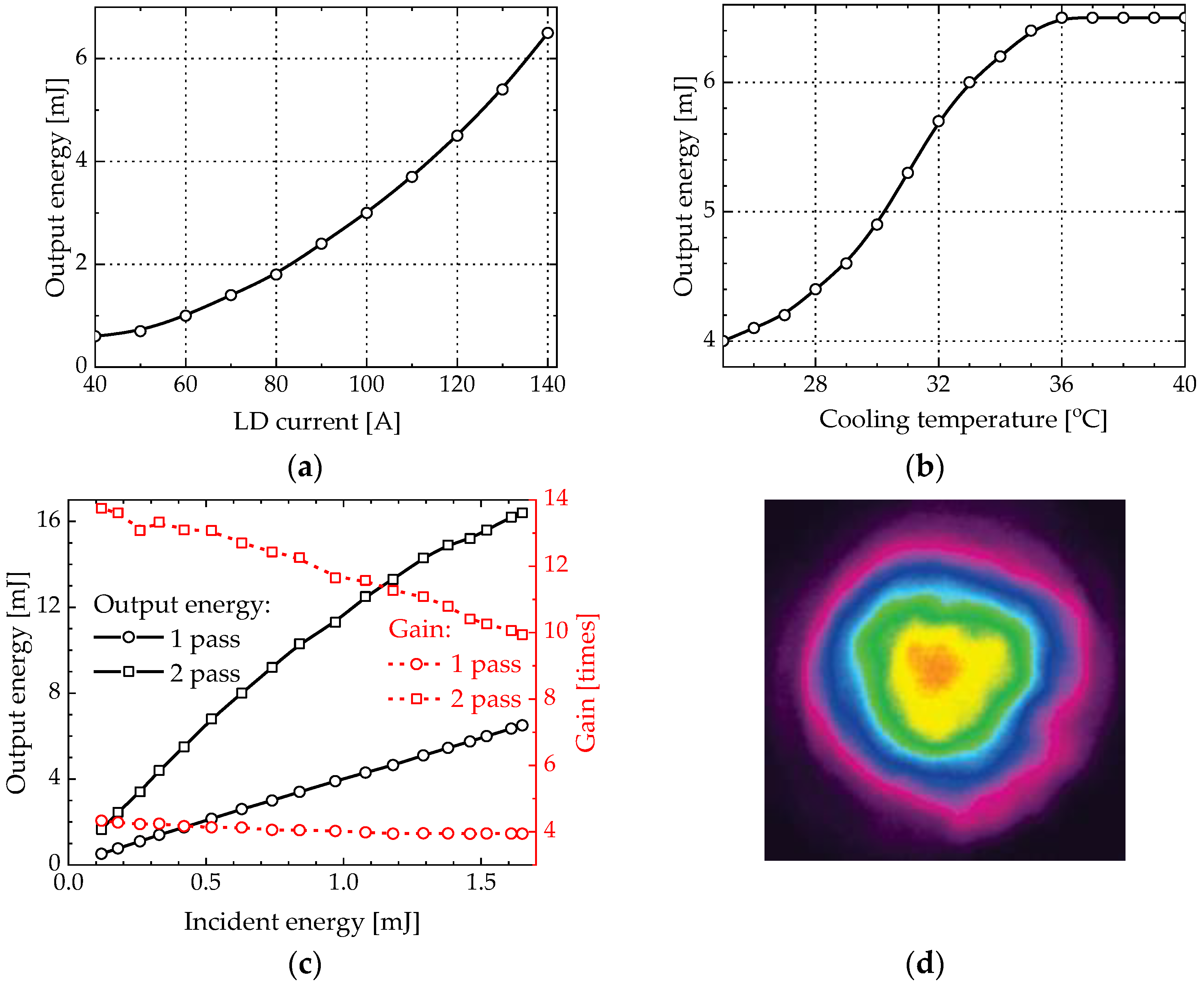
3.1. Optimization of Double-Pass Side Diode-Pumped Nd:YAG Amplifier

The maximum available energy from the mini-laser was limited to 1.65 mJ due to Fresnel losses in the optical elements. To achieve sufficient energy incident into the SBS compressor in our experiments, an additional amplifier was required. The performance of the corresponding Nd:YAG gain module was optimized by varying the pump laser diode (LD) current and cooling temperature. The maximum LD current was set at 140 A (Figure 2a) and limited by the power supply. The LD emission pulse width was 260 μs. The inability to independently control the temperature of the Nd:YAG rod and LD hampered the operation of the gain module. Since the LD emitted at a central wavelength of 802.6 nm at room temperature, the cooling water temperature had to be raised to match the Nd:YAG absorption band. Thus, the optimal cooling temperature of 36 °C was experimentally determined (Figure 2b). Finally, the beam-expanding telescope (F1, F2 in Figure 1) was optimized to achieve the best single-pass gain with a Gausian beam diameter of 3.4 mm (at 1/e2 level). The dependences of the output energy and gain after the first and second passes of the gain module on the energy of the incident pulse are shown in Figure 2c. After a single pass through the amplifier, an output energy of 6.5 mJ and a gain of ~4 times were achieved. In two passes, an output energy of 16.4 mJ and a gain of ~10 times were obtained. Optimizing the design of the gain module would allow for better performance. A distorted beam profile was obtained after two passes (Figure 2d), although the measured beam quality M2 = 1.41 was only slightly worse than M2 = 1.39 for the incident pulse. No deviations were observed in the spectrum of amplified pulses at a central wavelength of 1064.17 nm. The set of optimized parameters for the gain module is given in Table 1.

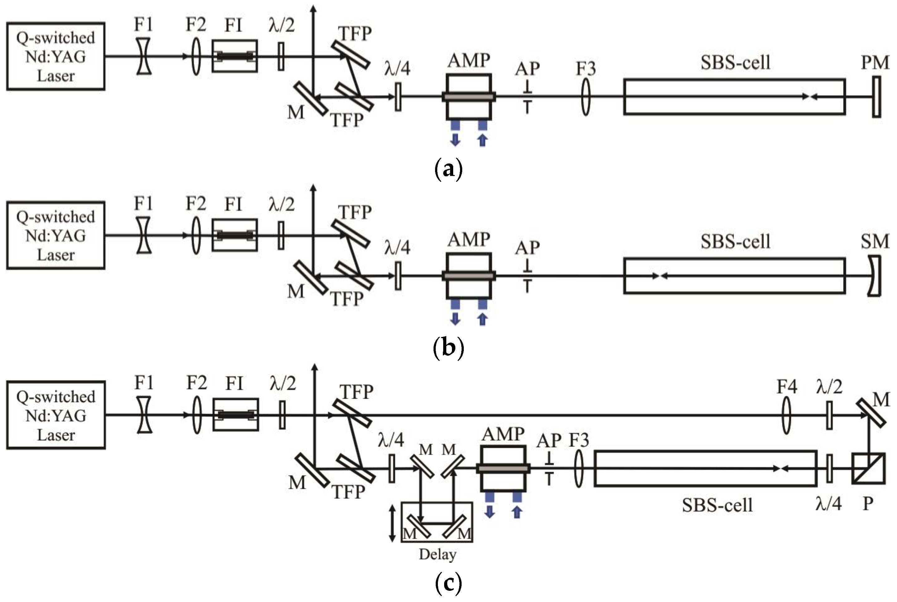
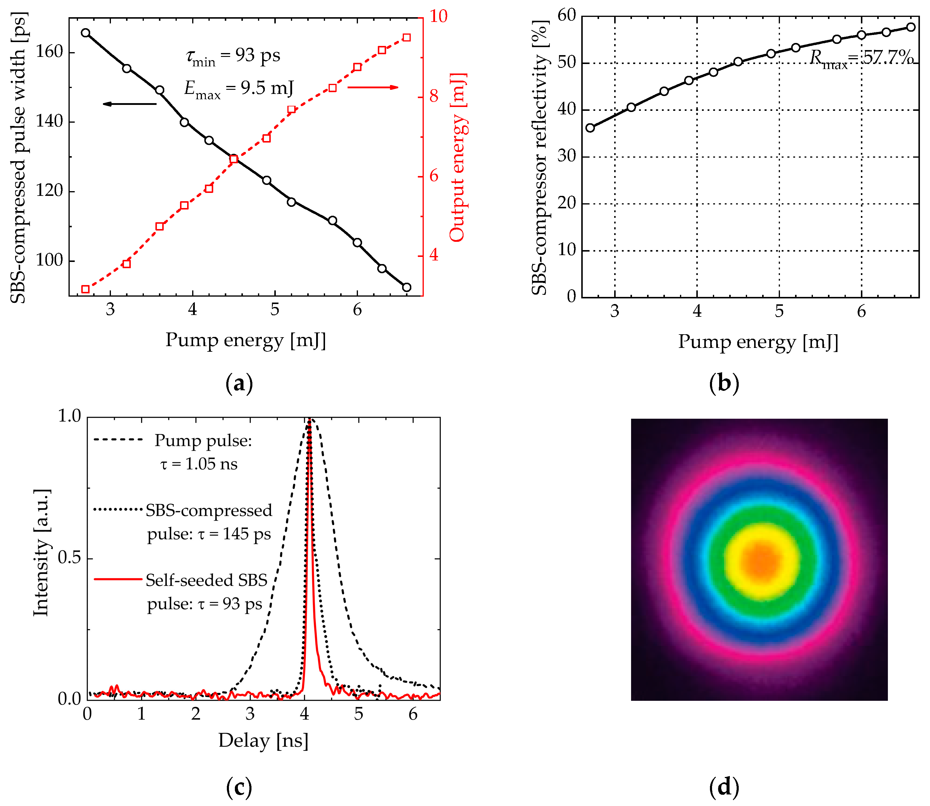
3.2. SBS Compressor with Plane Feedback Mirror and Phase-Conjugated Amplifier

In the general case, the buildup of an acoustic wave is localized in the focal region of the pump beam, propagating over a larger extend of the SBS medium. The distribution of the acoustic wave inside the SBS cell depends on the focal length. Short focal lengths will result in a more compact acoustic wave distribution. The disadvantage of a very short focal length is the high intensity, which can cause optical breakdown. When selecting a lens for an incident laser pulse of a given energy and duration, the intensity in the focal region must significantly exceed the threshold, but be below the optical breakdown value. For the experimental configuration with a plane feedback mirror (Figure 1a), a focusing lens (F3) with a focal length of 250 mm was determined to be optimal. In this case, the beam focusing position was ~3 cm from the rear window of the SBS cell. As the incident pump energy increased, the compressed Stokes pulse narrowed and the SBS compressor reflectivity increased (Figure 3a,b).
At maximum pump energy, the compression ratio Nτ = τp/τc reached 11.3 (where τp and τc are the pump and SBS-compressed pulse width, respectively). Focusing conditions were optimal for both the best compression ratio and maximum energy output. The shortest pulse width (FWHM) of the SBS-compressed pulse of 93 ps (Figure 3c, solid line) and the maximum output energy of 9.5 mJ (Figure 3a, dashed line) were achieved at the highest reflectivity of ~58% (Figure 3b). Although the compressed pulse was almost eight times shorter than the acoustic phonon lifetime of 0.72 ns in C8F18 [18], the curve (Figure 3b) has not yet reached saturation. Therefore, by increasing the pump energy, even higher compression ratio, reflectivity, and output energy can be obtained.
Without a feedback mirror (PM) in the SBS compressor, the compressed pulse was significantly longer (~145 ps in Figure 3c, dotted line) with a compression ratio of 7.2, and a maximum reflectivity of only ~31%. Installing this mirror reduced the SBS threshold by 20% (defined at a 1% SBS reflection level) compared to the unseeded configuration. As expected, the phase-conjugated amplifier demonstrated significantly better quality (M2 = 1.23) of the amplified beam (Figure 3d).

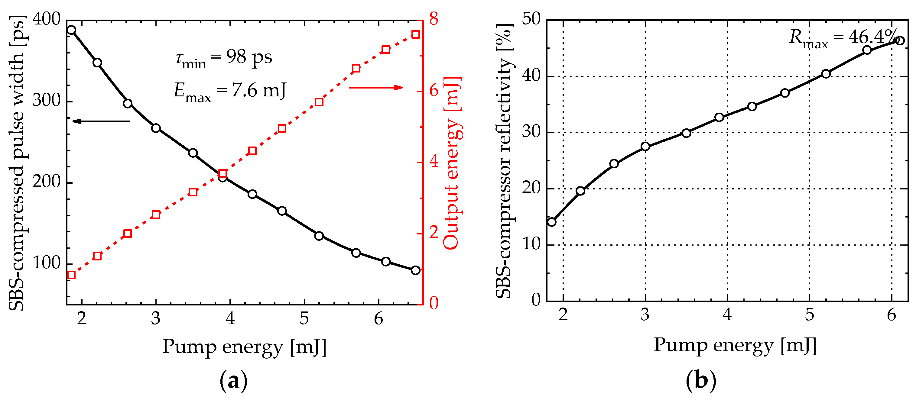
3.3. SBS Compressor with Spherical Mirror and Phase-Conjugated Amplifier

In the second configuration, the lens (F3) and the plane feedback mirror (PM) were replaced by a spherical (concave) mirror (SM in Figure 1b). An even higher compression ratio was expected as a result of increasing the interaction length. The optimal radius of the mirror was determined to be 500 mm with the beam focused to a depth of 3 cm from the front window of the SBS cell. This corresponded to the same optimal focal length as in the SBS compressor configuration with a plane feedback mirror (Figure 1a).
The dependence of the SBS-compressed pulse width (solid line) and the output energy (dashed line) on the pump energy in this configuration is shown in Figure 4a. The shortest pulse width of 98 ps (Nτ = 10.7) and output energy of 7.6 mJ were achieved at the maximum pump energy. As with the SBS compressor with plane feedback mirror, the focusing conditions were optimal for both the best compression ratio and maximum output energy. However, despite the longer interaction length in the SBS-active medium, no advantage in compression ratio or output energy was observed. This may be due to increased energy losses during multiple passes through the window of the SBS cell. The maximum reflectivity of the SBS compressor in this configuration was only 46.4% (Figure 4b).

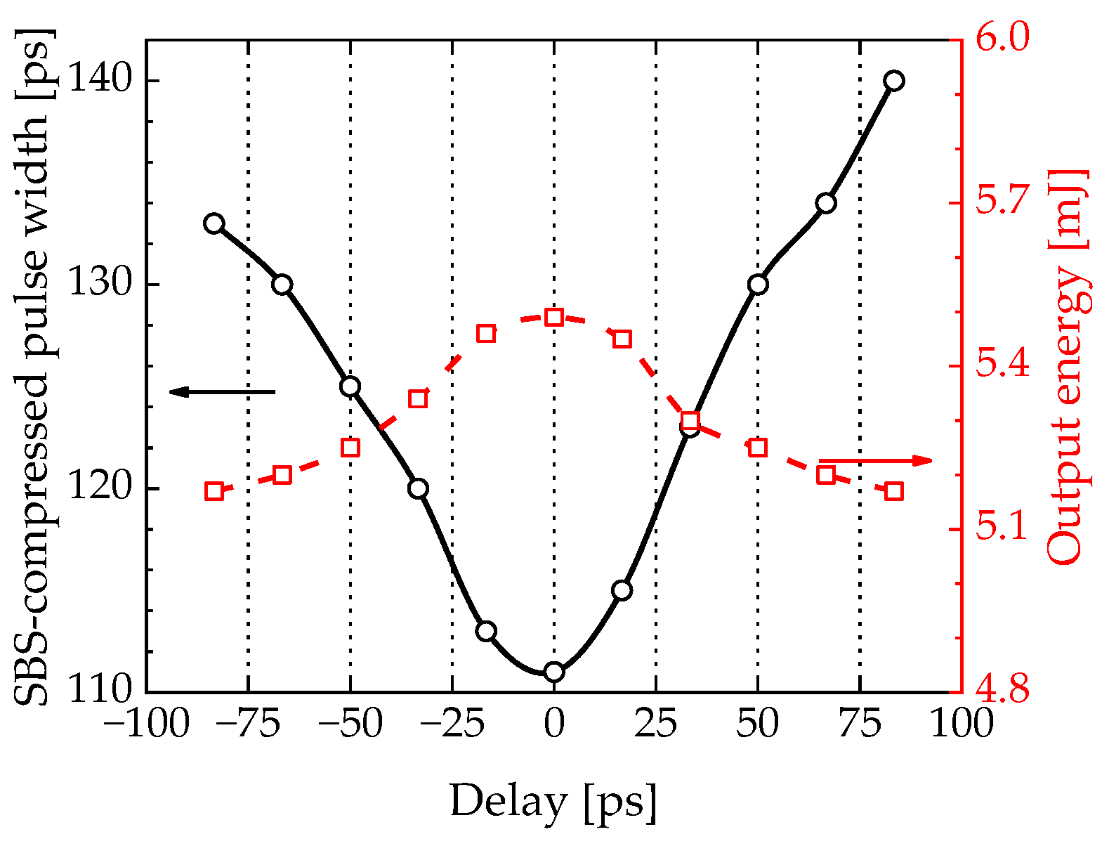
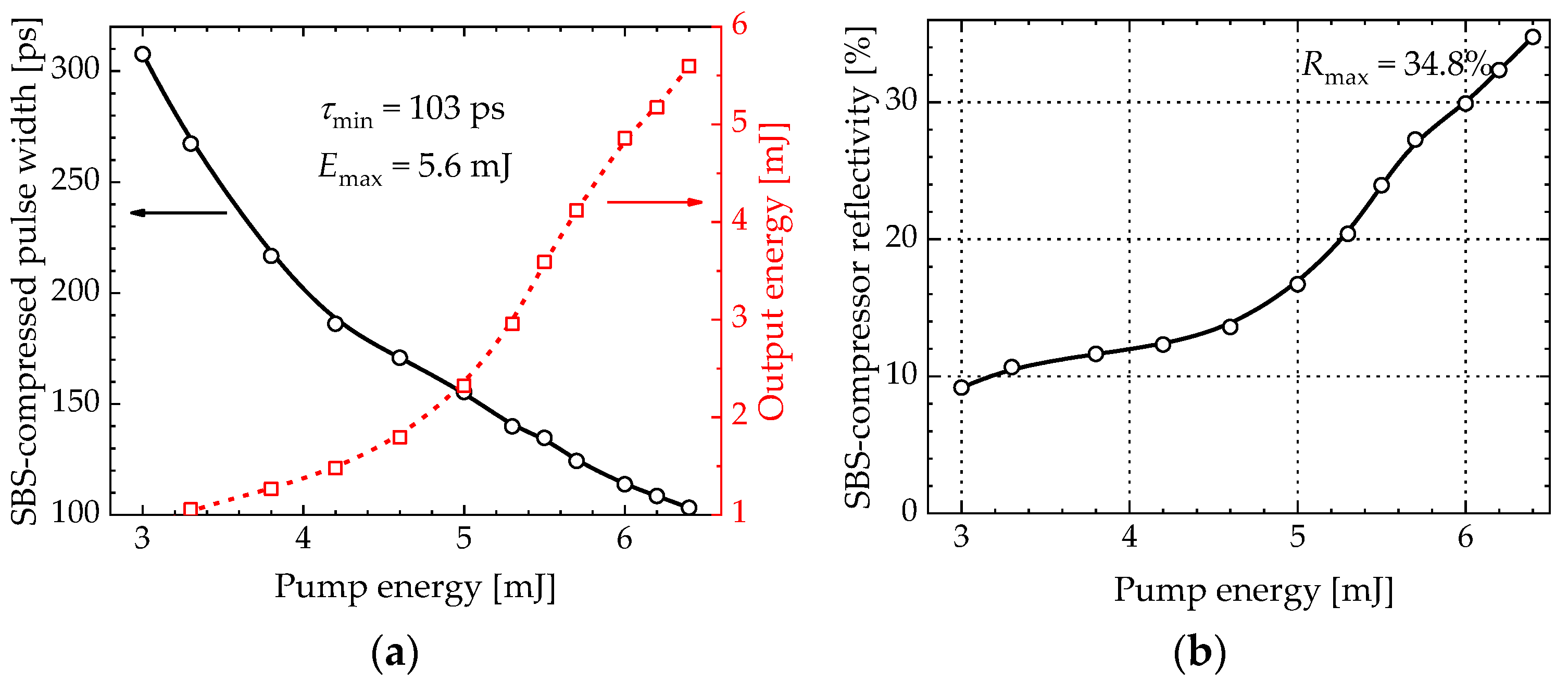
3.4. SBS Compressor with Variable Pulse Splitting and Phase-Conjugated Amplifier

In the last configuration with variable pulse splitting (Figure 1c), focusing lenses (F3 and F4) with optimal focal lengths of 250 mm and 500 mm, respectively, were used for the pump and seed beams. The shorter focal length of the F4 lens (250 mm or 300 mm) resulted in longer pulses after SBS compression. To avoid significant losses of available pump energy, a split of 0.2 mJ for seed pulses and 6.3 mJ for pump pulses was selected, respectively. It has been observed that adjusting the delay between split pulses was important to optimize the output energy and compression ratio (Figure 5).
With a delay variation of ~75 ps, the pulse width changed by ~25 ps, which corresponded to a 23% deviation from the optimal value. Then, the output energy decreased by ~0.25 mJ, i.e., only 5% of the maximum value. Thus, the precise temporal overlap of the seed and pump pulses had a much greater impact on the compression ratio than on the SBS compressor reflectivity. There was no significant difference in the sign of the relative mismatch between the arrival of the seed and pump pulses.
A compressed pulse width of 103 ps (Nτ = 10.2) and an output energy of 5.6 mJ were achieved with an SBS compressor reflectivity of 34.8% (Figure 6) at the optimal delay setting. Thus, the ability to control temporal overlap in a variable pulse split configuration, although providing an improvement over a traditional SBS compressor, did not show advantages over self-seeded schemes (Figure 1a,b), in contrast to [12]. We attribute this to the insufficient seed energy compared to the two previous configurations, as well as energy losses on numerous optical elements and the complexity of alignment. Since the available pump energy was already limited to ~6.4 mJ, further increasing the seed energy would lead to even greater pump depletion. Thus, optimization of such an energy-consuming setup with C8F18 requires an additional gain module, which was beyond the scope of the project.

3.5. Comparison of SBS Compressor Configurations

A comparison of the studied SBS compressor configurations (Table 2) shows that the best performance in terms of pulse width and output energy was obtained when using a plane feedback mirror. The incident 1.05 ns, 1.65 mJ pulses from the mini-laser were converted into 93 ps, 9.5 mJ output pulses with a compression ratio of 11.3. It is important to note that each of the schemes (Figure 1a–c) outperformed a conventional SBS compressor with 145 ps output pulses and a compression ratio of only 7.2. The size of the experimental layout 700 × 250 mm2 can be halved when designing a prototype. Adding a second gain module or using a four-pass amplifier would allow compressed pulse output energies of tens of mJ to be achieved.

3.6. Beam Characterization of Phase-Conjugated Amplifier

High-energy picosecond laser pulses are subject to requirements for beam quality and spatial stability. A smooth, diffraction-free beam is important for laser dermatology, and beam pointing stability is essential for spot stitching in direct laser interference patterning. However, the thermal effects, gain inhomogeneity, and diffraction inherent in MOPA cause beam distortion, and the long path leads to unstable beam position. The properties of SBS-PCM makes it possible to compensate for wavefront distortions. Since the SBS mirror reflectivity smoothly decays towards the periphery, like a soft aperture, diffraction distortions in multipass amplifiers are suppressed. Moreover, the beam reflected from the SBS mirror exactly repeats the path of incidence, regardless of the angular displacement of the SBS cell. The measured characteristics (Table 3) of the incident beam, the beam amplified in a double-pass amplifier with a plane mirror instead of the SBS cell, and the amplified beam after 11-fold pulse compression demonstrated the advantages of phase conjugation. The beam quality M2 has improved from ~1.4 to ~1.2, and unwanted ellipticity and astigmatism have been suppressed. This demonstrates the remarkable beam clean-up capabilities. Also noteworthy was the fourfold improvement in beam pointing stability compared to conventional MOPA.

4. Conclusions

All studied configurations of self-seeded perfluorooctane SBS compressor showed undoubted advantages compared to the commonly used scheme. Since SBS was not excited from the level of spontaneous scattering noise, its threshold was lowered, the reflectivity and compression ratio increased. In particular, the SBS threshold was lower by 20%, and the SBS compressor reflectivity reached ~58%, compared to ~31%. The shortest pulse width ~93 ps, compression ratio 11.3, and output energy ~9.5 mJ were achieved in an SBS compressor with a focusing lens and a plane feedback mirror. This is a significant improvement over the conventional design with a maximum compression ratio of 7.2 and 145 ps output pulses. Optical design options with a spherical mirror and variable pulse splitting were attractive due to longer interaction path or temporal overlap control, respectively. However, compared to using a feedback mirror, these alternative configurations showed no advantage in pulse width or output energy, but were more energy-consuming and difficult to align. It was also shown that the use of a phase conjugated mirror in a double-pass amplifier improved the beam quality M2 from ~1.4 to ~1.2, and suppressed ellipticity and astigmatism. The beam pointing fluctuations were reduced by a factor of 4 compared to a conventional MOPA without an SBS mirror. With an increase in output energy up to tens of mJ, this approach is promising in laser dermatology and direct laser interference patterning.

Author Contributions

Conceptualization, A.M.R.; methodology, A.M.R. and P.M.; validation, A.Č., P.M. and A.M.R.; formal analysis, A.M.R., P.M. and A.Č.; investigation, A.Č., P.M., A.M.R. and A.P.; resources, A.Č., P.M. and A.P.; data curation, A.Č. and P.M.; writing—original draft preparation, P.M., A.Č. and A.M.R.; writing—review and editing, A.M.R. and A.P.; visualization, P.M., A.Č. and A.M.R.; supervision, A.M.R.; project administration, A.M.R.; funding acquisition, A.M.R. All authors have read and agreed to the published version of the manuscript.

Funding

Research Council of Lithuania, agreement S-LU-22-3.

Institutional Review Board Statement

Not applicable.

Informed Consent Statement

Not applicable.

Data Availability Statement

Not applicable.

Acknowledgments

We are grateful to QS Lasers Ltd. for providing the compact Nd:YAG laser.

Conflicts of Interest

The authors declare no conflict of interest.

References

  1. McGarry, J.F.; Hoffman, E.D.; Degnan, J.J.; Cheek, J.W.; Clarke, C.B.; Diegel, I.F. NASA’s satellite laser ranging systems for the twenty-first century. J. Geod. 2018, 93, 2249–2262. [Google Scholar] [CrossRef] [PubMed]
  2. Sugioka, K. Progress in ultrafast laser processing and future prospects. Nanophotonics 2017, 6, 393–413. [Google Scholar] [CrossRef]
  3. Wu, D.C.; Goldman, M.P.; Wat, H.; Chan, H.L. A systematic review of picosecond laser in dermatology: Evidence and recommendations. Lasers Surg. Med. 2020, 53, 9–49. [Google Scholar] [CrossRef] [PubMed]
  4. Li, M.; Huang, Y.; Zhu, W. Clinical Application Progress of Picosecond Laser. J. Pract. Dermatol. 2019, 12, 223–226. [Google Scholar]
  5. Cole, B.; Goldberg, L.; Hays, A.D. High-efficiency 2 μm Tm:YAP Laser with a Compact Mechanical Q-Switch. Opt. Lett. 2018, 43, 170–173. [Google Scholar] [CrossRef] [PubMed]
  6. Keller, U.; Weingarten, K.J.; Kartner, F.X.; Kopf, D.; Braun, B.; Jung, I.D.; Fluck, R.; Honninger, C.; Matuschek, N.; der Au, J.A. Semiconductor saturable absorber mirrors (SESAM’s) for femtosecond to nanosecond pulse generation in solid-state lasers. IEEE J. Sel. Top. Quantum Electron. 1996, 2, 435–453. [Google Scholar] [CrossRef]
  7. Liu, L.; Li, N.; Liu, Y.; Wang, C.; Wang, W.T.; Huang, H.Z. 1 kHz, 430 mJ, sub-nanosecond MOPA laser system. Opt. Express 2021, 29, 22008–22017. [Google Scholar] [CrossRef] [PubMed]
  8. Cao, C.; Wang, Y.; Bai, Z.; Li, Y.; Yu, Y.; Lu, Z. Developments of Picosecond Lasers Based on Stimulated Brillouin Scattering Pulse Compression. Front. Phys. 2021, 9, 747272. [Google Scholar] [CrossRef]
  9. Wang, H.L.; Cha, S.; Kong, H.J.; Wang, Y.L.; Lu, Z.W. Rotating Off-Centered Lens in SBS Phase Conjugation Mirror for High-Repetition-Rate Operation. Opt. Express 2019, 27, 9895–9905. [Google Scholar] [CrossRef] [PubMed]
  10. Tsubakimoto, K.; Yoshida, H.; Miyanaga, N. High-average-power green Laser Using Nd:YAG Amplifier with Stimulated Brillouin Scattering Phase-Conjugate Pulse-Cleaning Mirror. Opt. Express 2016, 24, 12557–12564. [Google Scholar] [CrossRef] [PubMed]
  11. Andreev, N.F.; Grishin, E.A.; Kulagin, O.; Rodin, A. Picosecond Lasers with Brillouin and Raman Pulse Compression. In Proceedings of the International Conference ‘High Power Laser Beams (HPLB-2006)’, Nizhny Novgorod, Russia, 3–8 July 2006. [Google Scholar]
  12. Dement’ev, A.S.; Demin, I.; Murauskas, E.; Slavinskis, S. Compression of pulses during their amplification in the field of a focused counterpropagating pump pulse of the same frequency and width in media with electrostriction nonlinearity. Quantum Electron. 2011, 41, 153–159. [Google Scholar] [CrossRef]
  13. Marcus, G.; Pearl, S.; Pasmanik, G. Stimulated Brillouin scattering pulse compression to 175 ps in a fused quartz at 1064 nm. J. Appl. Phys. 2008, 103, 103–105. [Google Scholar] [CrossRef]
  14. Dane, C.B.; Neuman, W.A.; Hackel, L.A. High-energy SBS pulse compression. IEEE J. Quantum Electron. 1994, 30, 1907–1915. [Google Scholar] [CrossRef]
  15. Schiemann, S.; Ubachs, W.; Hogervorse, W. Efficient temporal compression of coherent nanosecond pulses in a compact SBS generator-amplifier setup. IEEE J. Quantum Electron. 1997, 33, 358–366. [Google Scholar] [CrossRef]
  16. Gaižauskas, E.; Piskarskas, A.; Smilgeavičius, V.; Staliūnas, K. Space and time structure of ultrashort pulses formed by opposed stimulated scattering of laser beams. Sov. J. Quantum Electron. 1987, 17, 650–653. [Google Scholar] [CrossRef]
  17. Guo, S.F.; Lu, Q.S.; Cheng, X.A.; Zhou, P.; Deng, S.Y.; Yin, Y. Influence of stokes component in reflected light on stimulated Brillouin scattering process. Acta Phys. Sin. 2004, 53, 1831–1835. [Google Scholar] [CrossRef]
  18. Bai, Z.; Wang, Y.; Lu, Z.; Yuan, H.; Zheng, Z.; Li, S.; Chen, Y.; Liu, Z.; Cui, C.; Wang, H.; et al. High compact, high quality single longitudinal mode hundred picoseconds laser based on stimulated Brillouin scattering pulse compression. Appl. Sci. 2016, 6, 29. [Google Scholar] [CrossRef]
Figure 1. Self-seeded SBS compressors: (a) with a focusing lens and a plane feedback mirror; (b) with a spherical mirror, and (c) with variable pulse splitting. FI—Faraday isolator; F1,2—beam expanding telescope; F3—focusing lens; λ/2 and λ/4—half-wave and quarter-wave retardation plates; PM—0° plane mirror; SM—spherical mirror; M—45° plane mirrors; TFP—dual thin-film polarizer; AMP—side diode-pumped Nd:YAG gain module; AP—aperture; P—polarizing cube.
Photonics 10 01060 g001
Figure 2. Performance of Nd:YAG gain module: dependence of the output energy after the first pass (a) on the LD current and (b) on the cooling temperature; (c) dependence of the output energy (solid lines) and gain (red dashed lines) after the first and second passes on the incident pulse energy; (d) near-field beam intensity profile after two-pass amplification.
Photonics 10 01060 g002
Figure 3. Performance of the SBS compressor with plane feedback mirror and phase-conjugated amplifier: (a) pulse width (solid line), output energy (red dashed line) of SBS-compressed pulses, and (b) SBS compressor reflectivity as a function of pump energy; (c) temporal shapes of SBS-compressed pulses with a plane feedback mirror (red solid line), without it (dotted line), and a pump pulse (dashed line); (d) near-field output beam intensity profile.
Photonics 10 01060 g003
Figure 4. Performance of SBS compressor with spherical mirror and phase-conjugated amplifier: (a) pulse width (solid line), output energy (red dashed line) of SBS-compressed pulses, and (b) SBS compressor reflectivity as a function of pump energy.
Photonics 10 01060 g004
Figure 5. Pulse width (solid line) and output energy (red dashed line) of SBS-compressed pulses as a function of the relative delay of the seed and pump pulses. The zero-delay value was selected for the best compression ratio and maximum output energy.
Photonics 10 01060 g005
Figure 6. (a) Pulse width (solid line) and output energy (red dashed line) of SBS-compressed pulse, and (b) SBS compressor reflectivity as a function of pump energy for a variable pulse split configuration.
Photonics 10 01060 g006
Table 1. Optimal operating parameters of the gain module.
ParameterValue
LD central wavelength802.6 nm
LD emission pulse width260 μs (FWHM)
LD current140 A
LD voltage49 V
Cooling temperature36 °C
Table 2. Performance overview of SBS compressor configurations. τmin—the shortest compressed pulse width (FWHM), Nτ—compression ratio, Emax—the maximum output energy, Rmax—the highest reflectivity.
SBS Compressor Configurationτmin [ps]NτEmax [mJ]Rmax [%]
without self-seeding1457.24.930.8
with plane feedback mirror9311.39.557.7
with spherical mirror9810.77.646.4
with variable pulse splitting10310.25.634.8
Table 3. Beam characteristics of incident, amplified, and SBS-compressed pulses.
Measurement ConditionsBeam Propagation Distance [mm]M2Astig-matismEllipti-cityBeam Pointing [%]
370400430460490
Nd:YAG
mini-laser output
Photonics 10 01060 i001Photonics 10 01060 i002Photonics 10 01060 i003Photonics 10 01060 i004Photonics 10 01060 i0051.390.391.221.28
After the 2nd pass of the amplifierPhotonics 10 01060 i006Photonics 10 01060 i007Photonics 10 01060 i008Photonics 10 01060 i009Photonics 10 01060 i0101.410.351.131.99
Compressed output pulsesPhotonics 10 01060 i011Photonics 10 01060 i012Photonics 10 01060 i013Photonics 10 01060 i014Photonics 10 01060 i0151.230.041.030.49
Disclaimer/Publisher’s Note: The statements, opinions and data contained in all publications are solely those of the individual author(s) and contributor(s) and not of MDPI and/or the editor(s). MDPI and/or the editor(s) disclaim responsibility for any injury to people or property resulting from any ideas, methods, instructions or products referred to in the content.

