Review

Functionalized Chiral Twisted Optical Fibers: A Review

by
Yifan Zhang
1,2,
Boyao Li
1,*,
Tianrong Huang
1,
Guiyao Zhou
2 and
Yaoyao Liang
3
1
School of Electronic Engineering and Intelligentization, Dongguan University of Technology, Dongguan 523808, China
2
Guangzhou Key Laboratory for Special Fiber Photonic Devices and Applications, School of Information Optoelectronics Science and Technology, South China Normal University, Guangzhou 510006, China
3
Centre de Nanosciences et de Nanotechnologies, CNRS, Univ. Paris-Sud, Université Paris-Saclay, 91120 Palaiseau, France
*
Author to whom correspondence should be addressed.
Photonics 2023, 10(9), 1025; https://doi.org/10.3390/photonics10091025
Submission received: 29 July 2023 / Revised: 26 August 2023 / Accepted: 31 August 2023 / Published: 7 September 2023

Abstract

:
With an increase in the volume of information exchange and perception, the demands for intelligent, miniaturized, and integrated optical devices for information acquisition are also increasing. As the core component of optical networks for transmitting information, further optimization of their structural characteristics to generate richer optical characteristics and apply them to information exchange and optical field control has become a key research hotspot. The introduction of chiral twist characteristics has led to new phenomena and applications in optical field transmission and the transformation of traditional optical fibers or microstructured optical fibers (MOF). Therefore, this review mainly begins with the principle of chiral optical fibers, introduces their preparation and latest application scenarios, and finally discusses their potential future development prospects.

1. Introduction

With the rapid development of information technology, optical fibers have become important components of communication systems and optical devices. Traditional optical fibers have limited scalability as carriers of functional optical devices due to their single structure. To overcome this limitation, a new modification method called “twisting” has attracted much attention in the field of optical fiber modification [1,2]. Chiral structures have been shown to alter the polarization state of light [3], so researchers have attempted to introduce this structure into optical fibers to form the so-called chiral twisted fiber. By twisting ordinary optical fibers or microstructure optical fibers [4,5], a periodic refractive index distribution can be formed in their axial direction. This special waveguide structure has generated unique optical phenomena in the transmission of polarized light, generation and transmission of angular momentum beams, and inter-mode interference [6,7,8]. Scientists have used theories such as spiral Bloch theory [9], mode coupling theory [10], and the photoelasticity effect [11] to explain it. Compared with traditional fiber modification methods, twisted fibers provide new features and applications in information capacity expansion [12,13], fiber lasers [9], amplifiers [14], and sensors [7,15,16].
In this review, to demonstrate the proof-of-concept of functional twisted optical fibers, several milestone studies are investigated, and their application fields are discussed. We begin with the theory of chiral twisted fibers and analyze their light-guiding mechanism. Then, we introduce the currently used methods for preparing twisted fibers and discussed their respective advantages and disadvantages [17,18,19,20]. Furthermore, we provide readers with a comprehensive summary of twisted fibers. In traditional optical fibers, the twisted structure forms a helical long-period grating structure for single-mode fibers. Its optical activity and circular birefringence make it excellent for polarization maintenance, interference sensing, and polarization filtering [21,22,23]. Microstructured fibers, due to their flexible structure, have obvious advantages in fabricating optical devices. Therefore, we also summarize the novel results obtained by introducing a twisted structure into the microstructured fibers. In twisted photonic crystal fibers, the multi-layered air channels affect the transmission of light in the fiber core. Under the influence of the helical lattice, the cladding light is forced to propagate along a helical path, and part of the axial momentum is converted into orbital angular momentum [24]. Various peculiar optical properties are explored by changing the arrangement of air channels [25]. When the twisted structure is introduced into hollow-core fibers, researchers have found that not only can the circular symmetry structure be changed, but also high circular birefringence and stable circular polarization characteristics can be maintained [26]. Additionally, hollow core fibers have an extremely low theoretical transmission loss, which provides new directions for the generation and transmission of Orbital Angular Momentum (OAM) beams [27]. Moreover, when multicore fibers are twisted, the inter-core coupling characteristics change [16], making them not only suitable for the generation of OAM but also highly promising for sensing, amplification, and other fields [28,29,30]. These studies indicate that twisted modified optical fibers have enriched applications in functional devices.
Although chiral twisted fibers have brought many novel applications due to their unique light-guiding mechanism, they still face many challenges in terms of axial stability, long-distance transmission, and rare-earth doping. In Section 4 of this review, we present the challenges, prospects, and promising opportunities of the future functional chiral fiber for functionalized devices. In summary, this paper provides a comprehensive overview of twisted optical fibers and their applications. It is hoped that this review will inspire more research in the field of optical fiber modification and promote the development of functionalized devices.

2. How to Describe the Chiral Twisted Fibers

Compared to traditional axially uniform optical fibers, the most obvious change in the chiral twisted optical fibers is their periodic modulation of the axial refractive index. However, the analysis of axially twisted media is different due to the differences in the fiber end faces and torsion conditions.

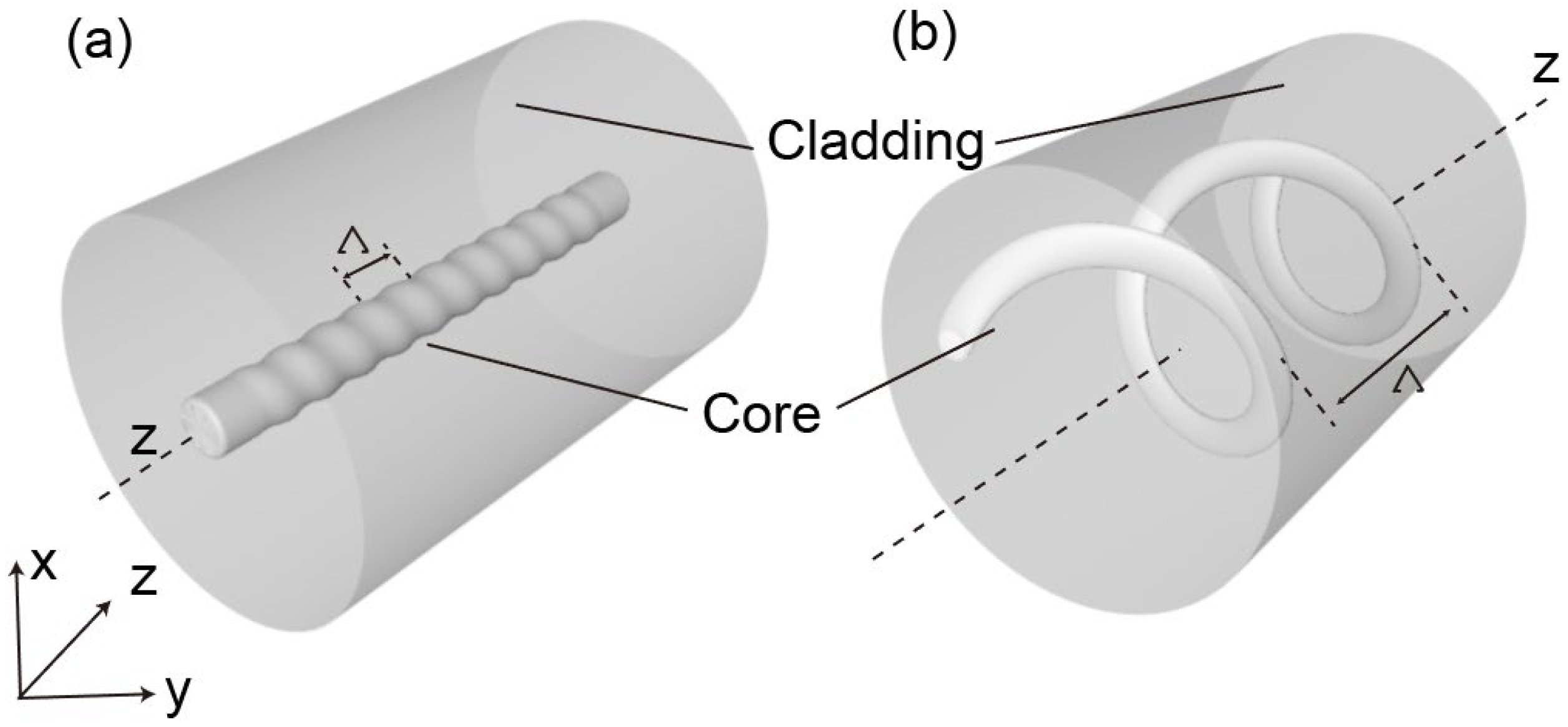
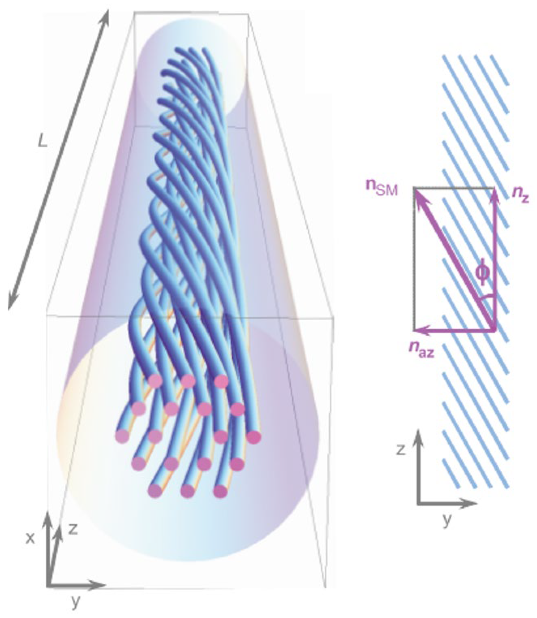
2.1. Analysis of Twisted Structure Characteristics in Single-Core Optical Fibers

Traditional single-core optical fibers introduce a refractive index difference between the core and cladding during the manufacturing process. When the fiber is melted and twisted, the refractive index distribution of its optical guiding channel also changes. Due to the introduction of this periodic structure, helical long-period fiber gratings (HLPGs) can induce coupling between the core and the cladding of the fiber, resulting in the generation of resonant peaks in specific wavelength bands [1], which is similar to conventional long-period fiber gratings whose resonant dips can be expressed as λ 0 = T n , where T is the LPGs grating period, and n is the refractive index difference between the core and cladding modes. The resonance wavelength of HLPGs, caused by phase matching, can be expressed as follows [17]:
λ 1 = ( n e f f c o n e f f c l , m ) Λ
where n e f f c o and n e f f c l , m are the refractive index of the core mode and m-th cladding mode, respectively. The resonance wavelength λ d of HLPGs shifts when there are changes in the refractive index distribution or twisting period Λ of the helical fiber. In Figure 1a, the core of the optical fiber is located at the center of the fiber, and through twisting, the cladding structure remains largely unchanged, whereas the core forms a uniform refractive index periodic distribution. When the grating period changes due to internal variations or external factors, such as temperature, pressure, bending, etc., HLPGs exhibit different transmission spectrum results. Typically, we classify the twisting of the fiber into clockwise and counterclockwise directions, and when light enters the twisted fiber with different polarization states, different optical guiding characteristics are also observed. Moreover, externally applying twists in different directions can also change the period of the HLPG, resulting in the resonance wavelength shifting in different directions. Therefore, HLPGs have great potential for applications in polarization optical transmission, circular birefringence, and torsion sensing.
In addition, when the fiber core is away from the axis of the fiber waveguide, the twisted characteristics become more complex and cannot be analyzed solely by relying on the theory of long-period gratings, as shown in Figure 1b. When the fiber core of the twisted fiber is bent, the cladding whispering gallery modes (WGMs) couple with the twisted core mode. Therefore, under the influence of the bending and twisting of the fiber core, the guided core is transformed into cladding WGMs [4].

2.2. Analysis of Twisted Structure Characteristics in Microstructured Optical Fibers

The torsion structure becomes more complex, such as the torsion of a microstructure optical fibers as shown in Figure 2. At this point, due to the interaction between different structures, the approximation algorithm using single-core optical fibers is not very reliable. More rigorous transformation optics model analysis methods are needed.
Introducing twisting into an optical fiber leads to changes in the refractive index distribution of the material. In electromagnetics, these variations in the material can be translated into changes in the coordinates from {x, y, z} to {x′, y′, z′} [5,31,32]. The new coordinate system’s permeability and permittivity tensors are provided by
ε = J 1 ε J T det ( J 1 )   and   μ = J 1 μ J T det ( J 1 )
where ε and µ are the permeability and permittivity tensors of the fiber in {x, y, z}, respectively, and J 1 is the inverse of the Jacobian matrix:
J 1 = x x x y x z y x y y y z z x z y z z
Coordinate transformations in optics can reduce the dimensionality of certain problems by selecting a coordinate system for a waveguide that is independent of one of its coordinates, taking into account the geometric and material properties. In a twisted optical fiber, we can convert the Cartesian coordinate system to a helical coordinate system, with the corresponding relations as follows [3]:
x = x cos ( A z ) y sin ( A z ) y = x sin ( A z ) + y cos ( A z ) z = z
where A = 2π/Λ represents the twist rate, which describes the angle of rotation −Az of the helical coordinate system’s axes relative to the Cartesian coordinate system’s x and y axes around the z-axis. In the twisted coordinate system, each line that is parallel to the z-axis is represented as a helix in the Cartesian coordinate system. These helices have a pitch distance equal to Λ and are considered left-handed for positive A. The Jacobian matrix J 1 utilized in this situation’s inverse is calculated as follows:
J 1 = cos ( A z ) sin ( A z ) A y sin ( A z ) cos ( A z ) A x 0 0 1 = 1 0 A y 0 1 A x 0 0 1 cos ( A z ) sin ( A z ) 0 sin ( A z ) cos ( A z ) 0 0 0 1 = 1 0 A y 0 1 A x 0 0 1 R ( A z )
where det ( J 1 ) = 1 and R(Az) is the spiral matrix. Based on Equations (1) and (4), the corresponding ε′ can be expressed in the helical coordinate system as follows [3]:
ε ( x , y , z ) = ε ( x , y , z ) 1 + A 2 y 2 A 2 x y A y A 2 x y 1 + A 2 x 2 A x A y A x 1
Using the above calculation, the spiral of the material is transformed into the coordinate system of the spiral. The ε′ in the twisted coordinate system can be expressed in the Cartesian coordinate system. Given the x and y coordinates of the material, the helical coordinates can be represented by a formula independent of z. Ultimately, the complex three-dimensional spiral calculation is transformed into a two-dimensional calculation.

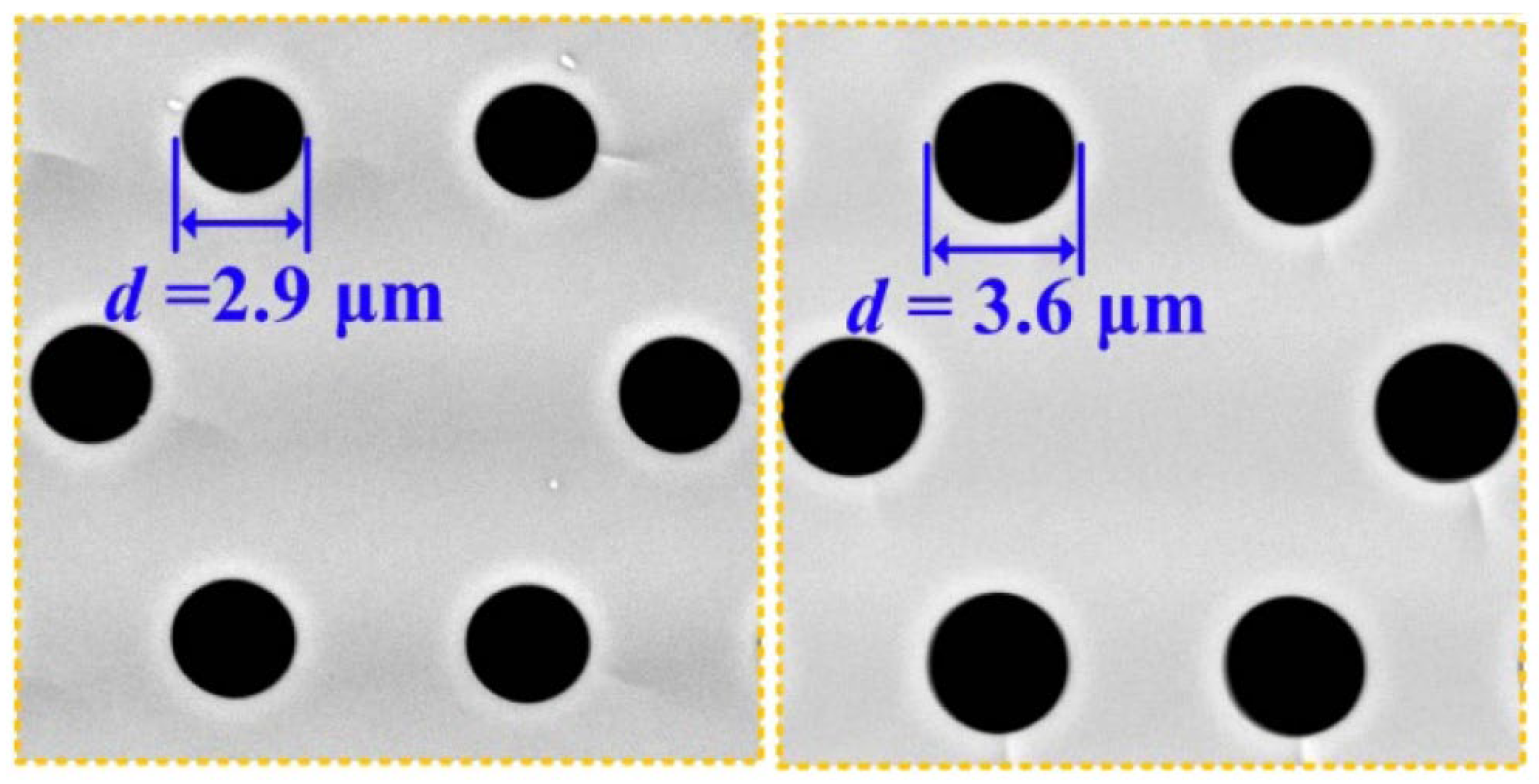
2.3. Fabrication Process of the Twisted Optical Fiber and Challenges

To fabricate a twisted structure in fibers, there are some common methods, as shown in Figure 3. The first method involves using a high-temperature hydrogen–oxygen flame to heat and soften the fibers. By controlling the intensity of the flame and using motors at both ends, the fiber can be twisted and fabricated accordingly. Zhong et al. proposed a method using a hydrogen–oxygen flame to etch twisted structures into fibers [17]. Basic devices with a hydrogen–oxygen flame platform, two translational platforms, and rotators comprise the fabrication setup. These components are utilized to carefully regulate the twisting and etching processes on the surface of the fiber. By utilizing this method, twisted fiber gratings can be fabricated in a stable manner, ensuring their long-term preservation. The controlled twisting and precise etching process enable the creation of durable and reliable twisted fiber gratings that can maintain their properties over an extended period of time. This stability and longevity make the fabricated gratings suitable for various applications in fiber optics and photonics.
Another method for fabricating twisted fibers involves the use of a CO2 laser [18,33,34]. The power of the CO2 laser is controlled by a computer, allowing for more precise and stable heating of the twisting region. Shin et al. created a twisted single-mode fiber (SMF) with CO2 laser beam exposure and examined its properties experimentally [19]. They achieved the formation of a periodic twisted structure by irradiating the fiber with a CO2 laser while uniformly rotating the motor along the fiber axis. This method enables precise control of the twisting period and allows the generation of resonance within extremely short grating lengths.
Automatic arc discharge technology is also utilized for the fabrication of twisted fibers. Sun first used commercial fusion splicer technology to create a twisted structure in the conventional SMFs [20]. The system consists of two electrodes, a spiral motor, and a fixture for holding the fiber in place. By investigating the effect of arc current on the formation of twisted fibers, they determined the appropriate current values to apply, resulting in clear resonance peaks and low insertion loss.
The above-mentioned fabrication methods for twisted optical fibers also face their respective challenges. Although the hydrogen–oxygen flame method has relatively low instrument requirements, the flame intensity is difficult to control, therefore resulting in mediocre sample uniformity. The CO2 laser method requires precise focusing equipment. In addition, the impact of the CO2 laser can cause radial disturbances. As for automatic arc discharge technology due to motor range limitations, the fabricated samples are usually short, which makes long-distance transmission difficult to achieve. Recently, researchers have attempted to introduce twisting during the fiber-drawing process [21]. However, the current twisting period is relatively short, and further exploration is needed for this method. To achieve a stable axial structure and longer sample length for twisted optical fibers, more innovative processes await exploration by researchers.

3. Applications of Chiral Twisted Fibers

Based on the above-mentioned unique structural features of chiral twisted fibers, they can be employed in a wide range of functional device applications. The benefits of the chiral twisted technique paired with various functional fibers are explored more in the following sections. Furthermore, the special uses and significance of functional chiral twisted fibers are explored.

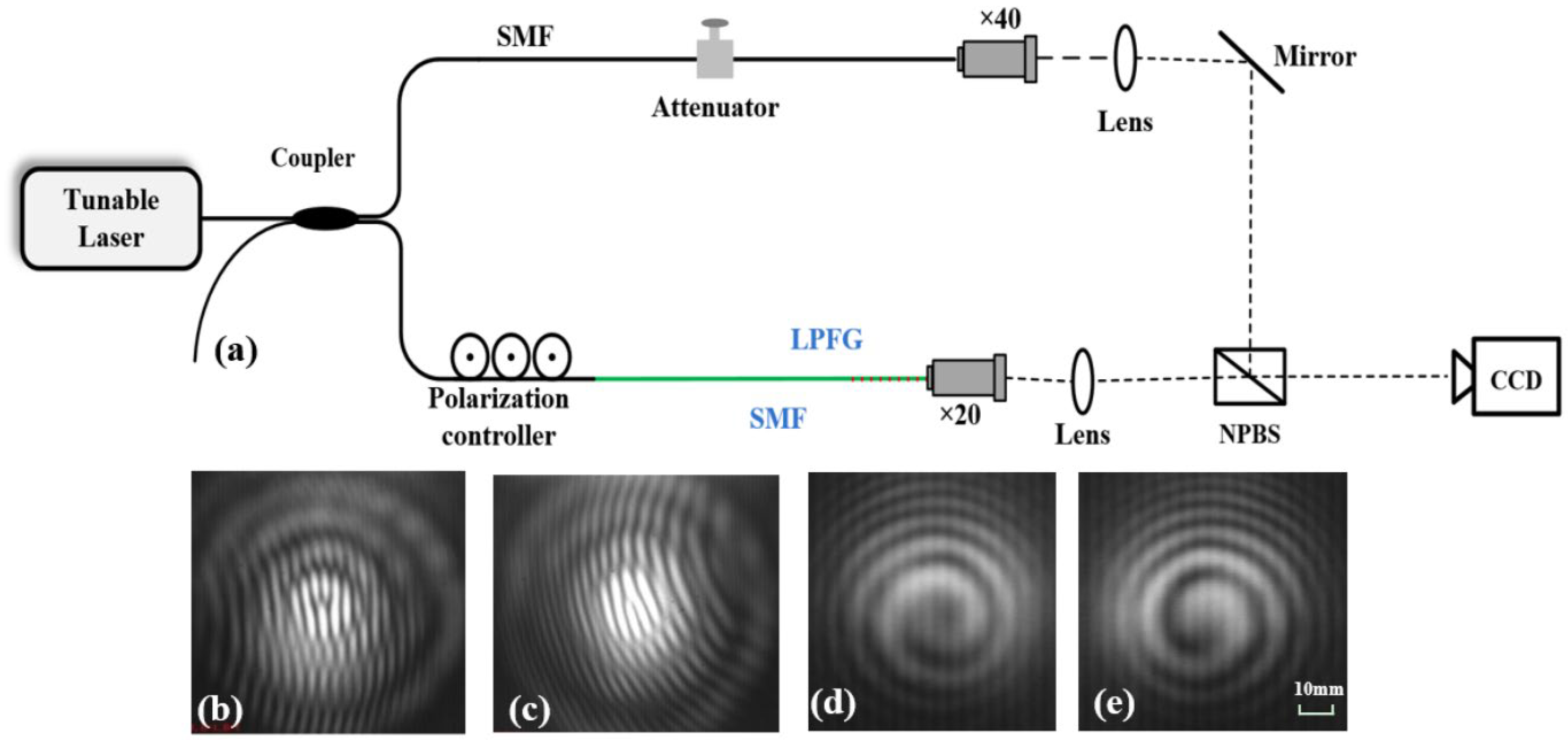
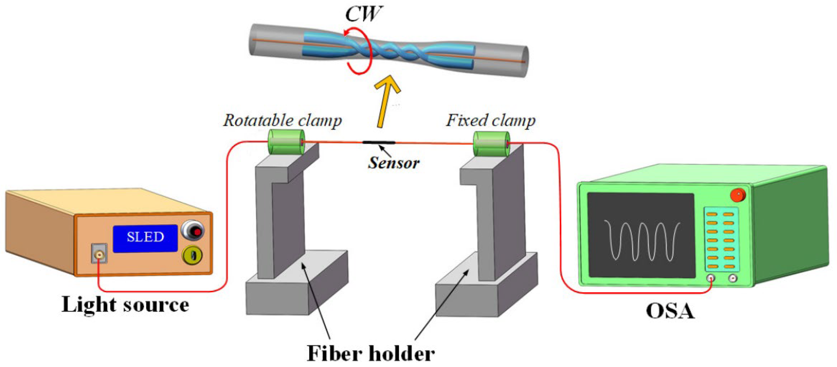
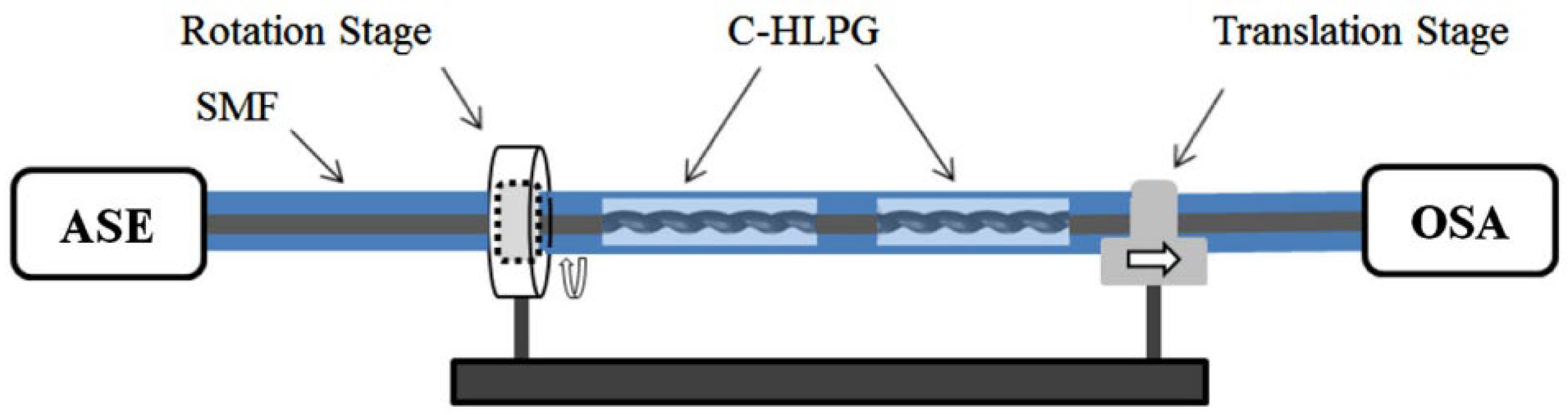
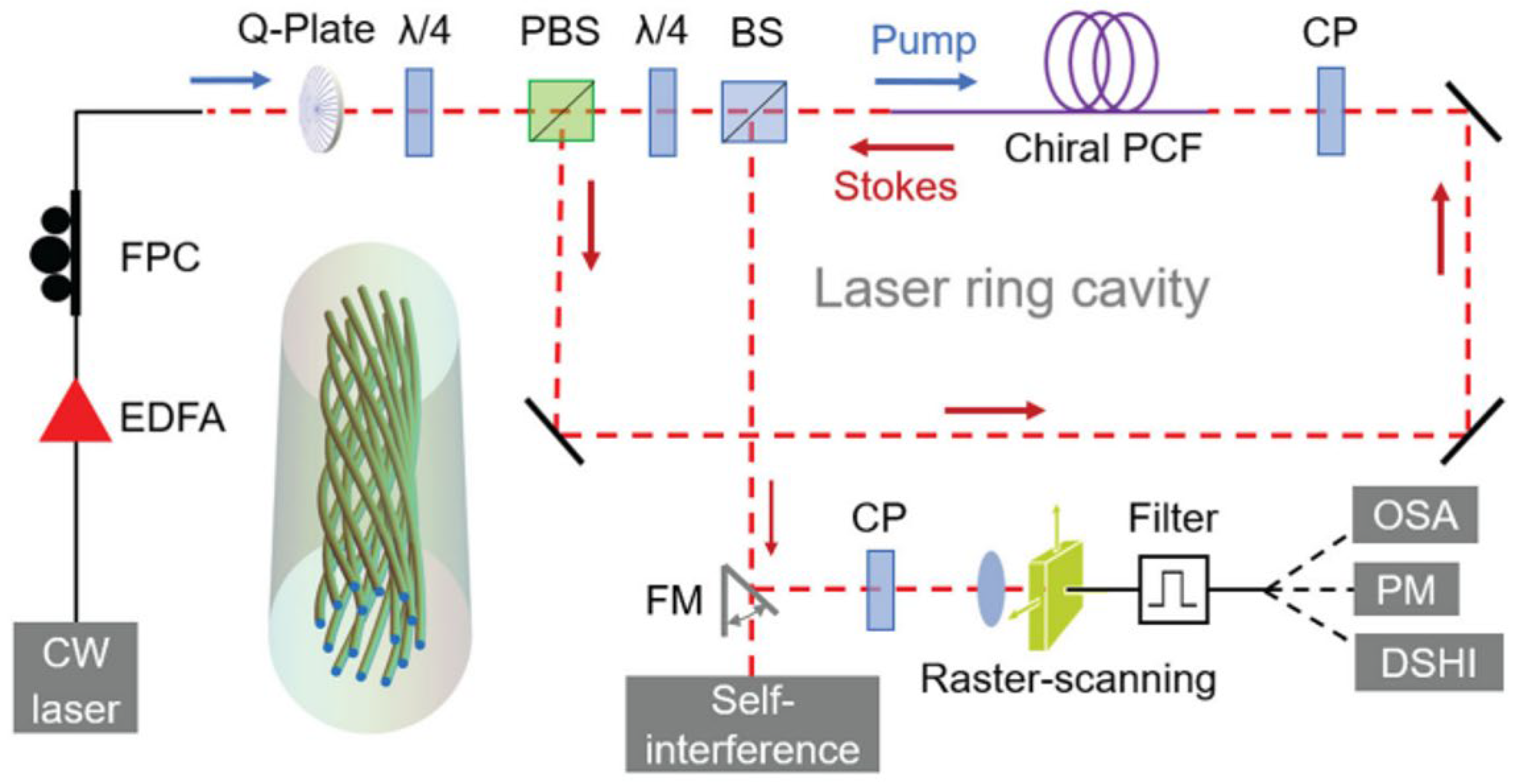
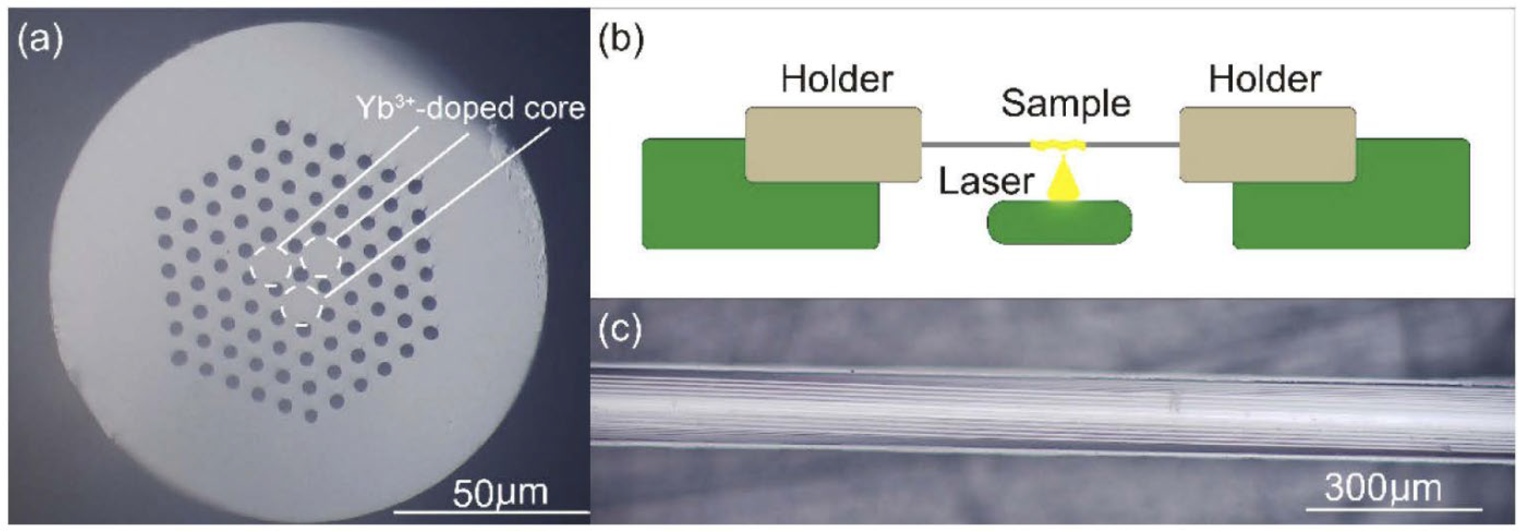
3.1. Characterization Process of Chiral Twisted Fibers

Different types of optical fibers, especially microstructured fibers, exhibit various optical phenomena due to their flexible and diverse internal structures, especially after introducing twisted structures. Moreover, significant changes in their light-guiding characteristics occur with variations in the fiber core position and twist period, allowing for the fabrication of optical devices with different functionalities. Commonly used devices include OAM generators, OAM transmitters, polarizing filters, amplifiers, and sensors. Different characterization methods are required for each specific device.
In the application of OAM beams, the method of spatial optical interference is commonly used to verify the generation of OAM light and explore its order [19]. In Figure 4a, the light from a tunable laser enters the two interferometer arms through a beam splitter. One of the arms passes through a polarization controller and then enters a long-period grating made of twisted fibers. After being focused by an objective lens, it enters a non-polarizing beam splitter (NPBS). The other arm serves as the reference beam and interacts with the first beam after passing through a fiber attenuator to adjust the power, and then enters the NPBS. The interference patterns are recorded and analyzed using a back-end charge-coupled-device (CCD) camera. The resulting interference images of different samples and light sources are shown in Figure 4b–e, allowing for the analysis of the helical phase of the generated OAM beams.
Spectral analysis is crucial for analyzing the characteristic peaks generated by the inter-mode and inter-core interference in twisted fibers. In Figure 5, a broadband light source is received by an optical spectrum analyzer (OSA) after passing through the twisted fibers [35]. The characteristic peaks generated by the interference can be obtained and analyzed. Additionally, the transmission spectrum can be used to verify the transmission loss of OAM beams with different orders generated by twisting and determine their effective transmission wavelengths [12]. This plays an important role in studying the expansion of the fiber transmission capacity and in reducing transmission loss [27].
In addition, twisted fibers have recently made good progress in fields such as amplification and lasers [9,14]. Therefore, when characterizing these devices, researchers will design corresponding experimental plans according to their needs. Twisted fibers are applied to various fields with the deepening of research, and their optical properties still have the potential to be further explored. Therefore, the corresponding characterization methods will also be updated accordingly.

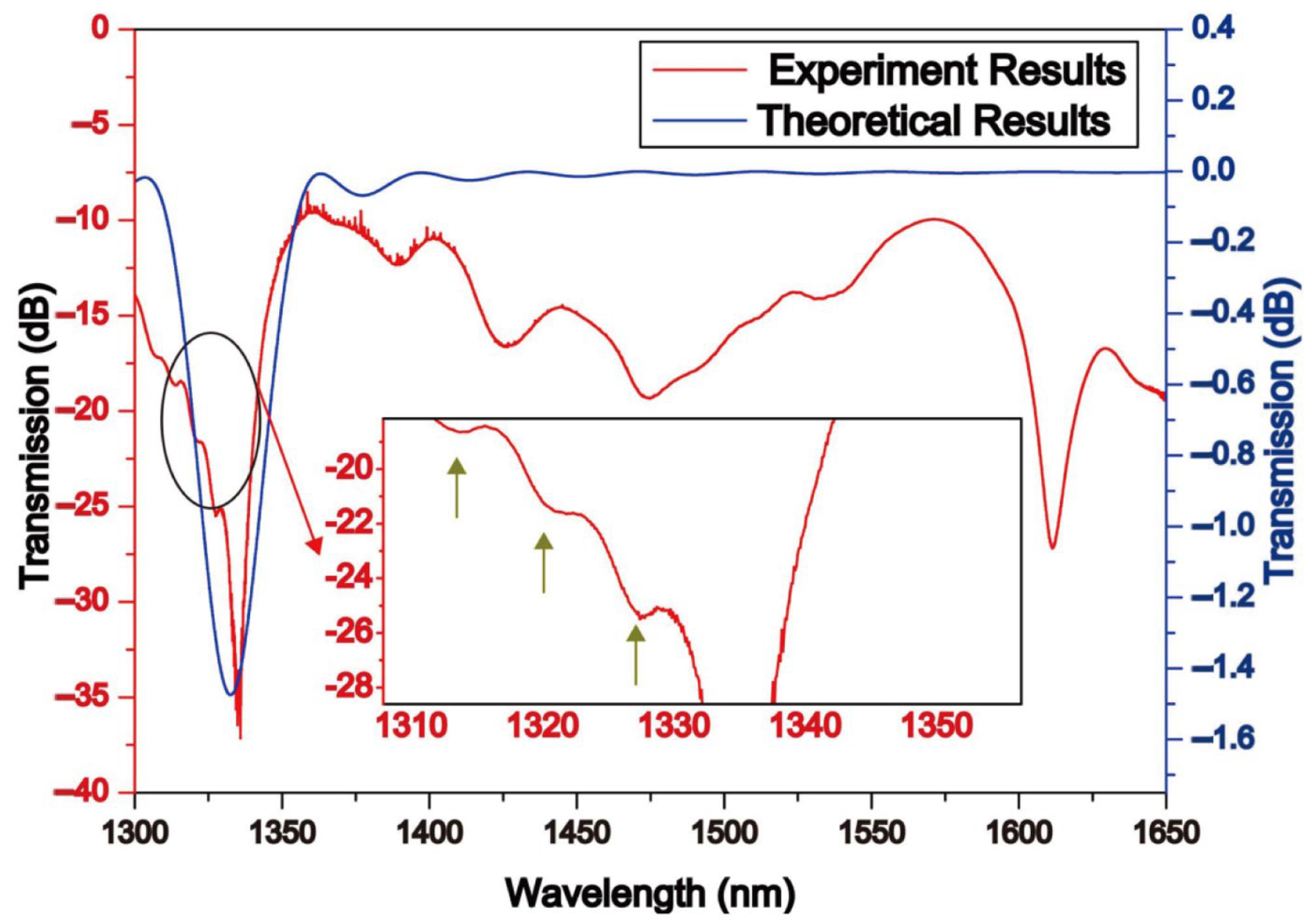
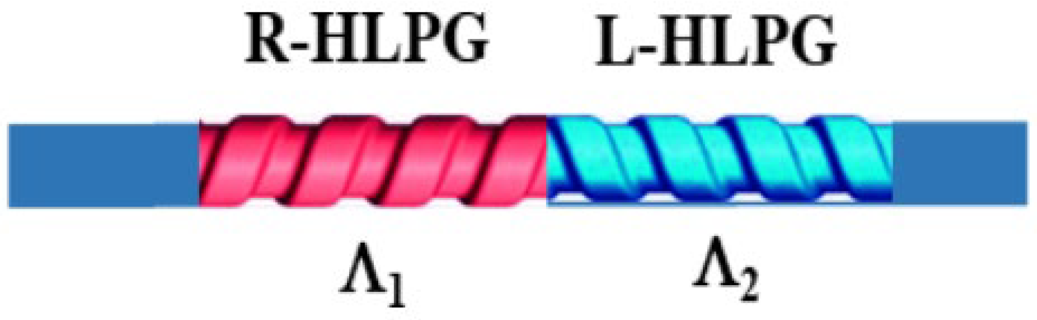
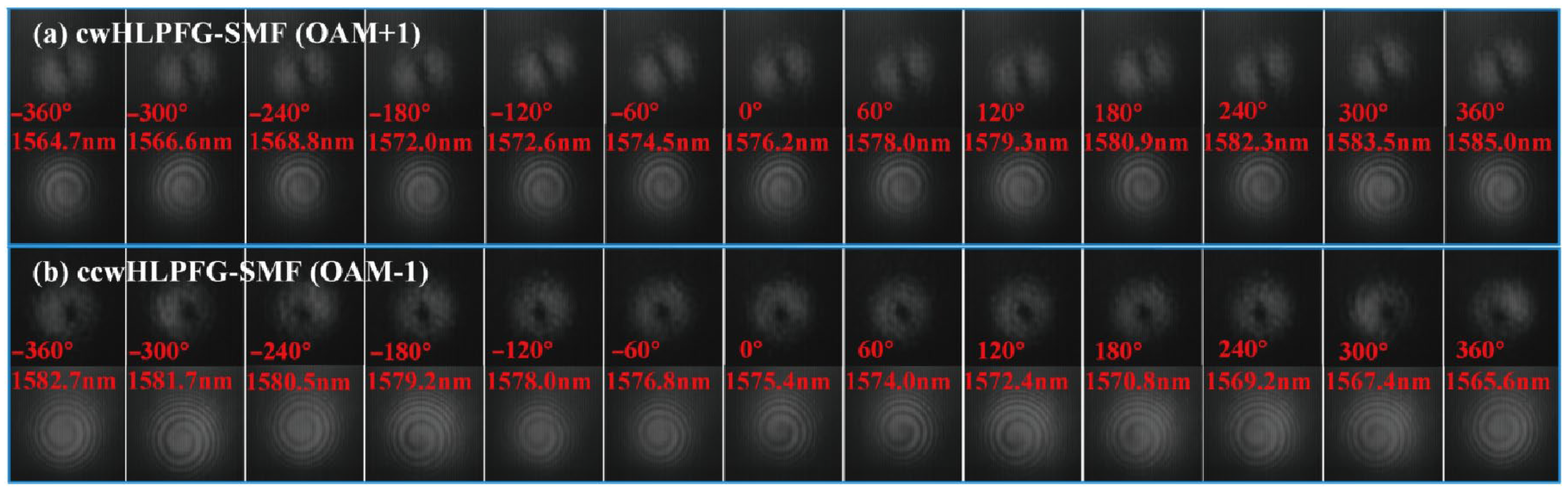
3.2. Traditional Single Core Chiral Twisted Fibers

Since the early stages of fiber optics, twisted-induced birefringence has become a prominent area of research. The concept of twisted fiber [36] was proposed in 1979 by Ulrich. They discussed the change in polarization along the twist direction. Using the first principles, they employed perturbation methods to calculate the coupling between the two degenerate modes. Furthermore, the experimental results validated the correctness of this theory and provided an approximate calculation of the g-factor. Since then, research on twisted fibers has become increasingly rich and diverse.
Twisted SMFs undergo interesting changes in their polarization state due to the alteration of birefringence. After twisting, the single-mode fibers exhibit a significant degree of optical rotation, but they demonstrate almost no polarization anisotropy during the twisting process [37]. Therefore, twisted fibers can effectively eliminate the polarization mode dispersion. The measurement of circular birefringence in twisted fibers is particularly relevant among them. Andrea proposed a new method for measuring circular birefringence in long twisted SMF [38]. The method employs polarization-sensitive optical time-domain reflectometry. To further validate the fundamental effect of birefringence in twisted fibers, Diana analyzed the developed birefringence matrix for twisted fibers [39]. They discovered that the Jones birefringence caused by twisting the birefringent optical fibers exceeds the values of Jones birefringence caused by electric and/or magnetic fields in the bulk birefringent material by several orders of magnitude. Furthermore, as shown in Figure 6, they also found that the twisting of erbium-doped fibers has a greater impact on the fiber’s polarization characteristics compared to non-doped fibers. This is attributed to the influence of the glass matrix composition and fiber structure.
The use of twisted optical fibers to construct HLPG structures has recently been proposed in multiple fields. Because of the grating’s helical construction, clockwise or anticlockwise twisting can shorten or lengthen the period of grating, causing the resonance wavelength to shift in a different direction. Therefore, HLPG can be effectively applied in the fields of temperature, torsion, and refractive index sensors [7,15,17,18,33,40,41,42,43]. Li analyzed the effects of LPG and intermodal interference in chiral twisted single-mode fibers (CTSMF) [44]. In Figure 7, the LPG model established using mode resonance theory showed good agreement with the experimental results. These characteristic dips are generated by the periodic refractive index variation in the twisted core region, forming a structure similar to that of LPG. Furthermore, the response of the CTSMF to external environmental factors was also analyzed. These outstanding results of CTSMF show that it is a strong contender in the sectors of sensing and communications. By controlling the length and direction of the twist pitch, effective applications of the CTSMF in sensing can be achieved. An improved HLPG method was proposed by Zhao to achieve the real-time measurement of multiple parameters [7]. To further enhance sensitivity, a fiber taper was introduced in a twisted structure [15]. The experimental results show that the intensity of the transmission peaks varies inversely when the fiber is twisted in different directions. In 2020, to measure torsion and strain simultaneously, Xian proposed a cascaded helical long-period grating (C-HLPG) with two distinct gratings that fabricate molten state duration durations (MSDTs) in Figure 8. Torsion and strain can be distinguished with accuracies of ~120 µε and ~0.12 rad within the ranges of 0~1744 µε and −240°~240°, respectively. The C-HLPG with various MSDTs offers outstanding prospects as torsion and strain sensors, as well as future development for multiparameter fiber sensors and innovative fiber components.
In addition to sensing applications, CTSMF also plays a significant role in the generation and selection of modes [6,34,45]. A straightforward method for validating the mode-selection principles used in a single-helix helical long-period fiber grating (SHLPG) has been established both theoretically and experimentally [8]. This is performed by exploring and analyzing the polarization dependence loss (PDL) and circular dichroism (CD) spectra of the SHLPG. Moreover, the CTSMF is considered a highly promising OAM beam shaper and generator. Wang invented and experimentally proved a unique method for simultaneously generating the first and second OAM modes using two successively cascaded helical long-period fiber gratings (ccHLPGs), as shown in Figure 9. The first-order OAM mode had a conversion efficiency of 94%, and the second-order (l = 2) OAM mode had an efficiency of 83%. When the twisting angle changed, the excited OAM modes also varied accordingly. Based on the oxyhydrogen flame method, Liu presented an all-fiber torsion-tunable orbital OAM mode generator [46]. To excite the 1-order and 3-order OAM modes, SMF and six-mode fiber (6MF) HLPFGs were utilized. The evolution of the mode field distributions and their interference patterns with the Gaussian beams with varying torsion angles are shown in Figure 10.

3.3. Chiral Twisted Microstructured Optical Fibers

Compared to traditional SMFs, twisted structures in the form of MOFs offer more choices and greater possibilities in the field of twisted fiber applications due to their versatile and flexible structure. In addition to enhanced mode selection, mode field control, and OAM mode generation [48,49,50], chiral twisted microstructured fiber (CTMOF) has also been found to have great potential in fields such as lasers [9], sensing [51,52,53], and transmission [54,55,56]. Here, we have summarized some applications, including chiral twisted photonic crystal fiber (CTPCF), chiral twisted hollow-core fiber (CTHCF), and chiral twisted multicore fiber (CTMCF), and found that microstructured fibers play a crucial role in improving the functionality of twisting.

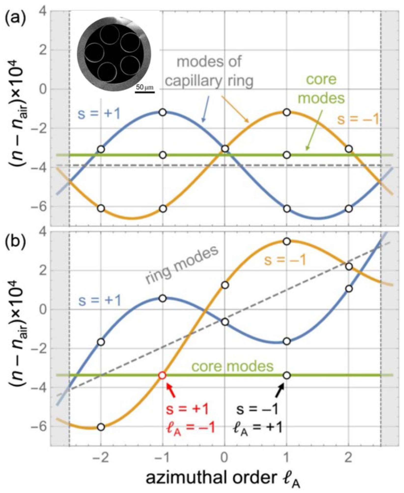
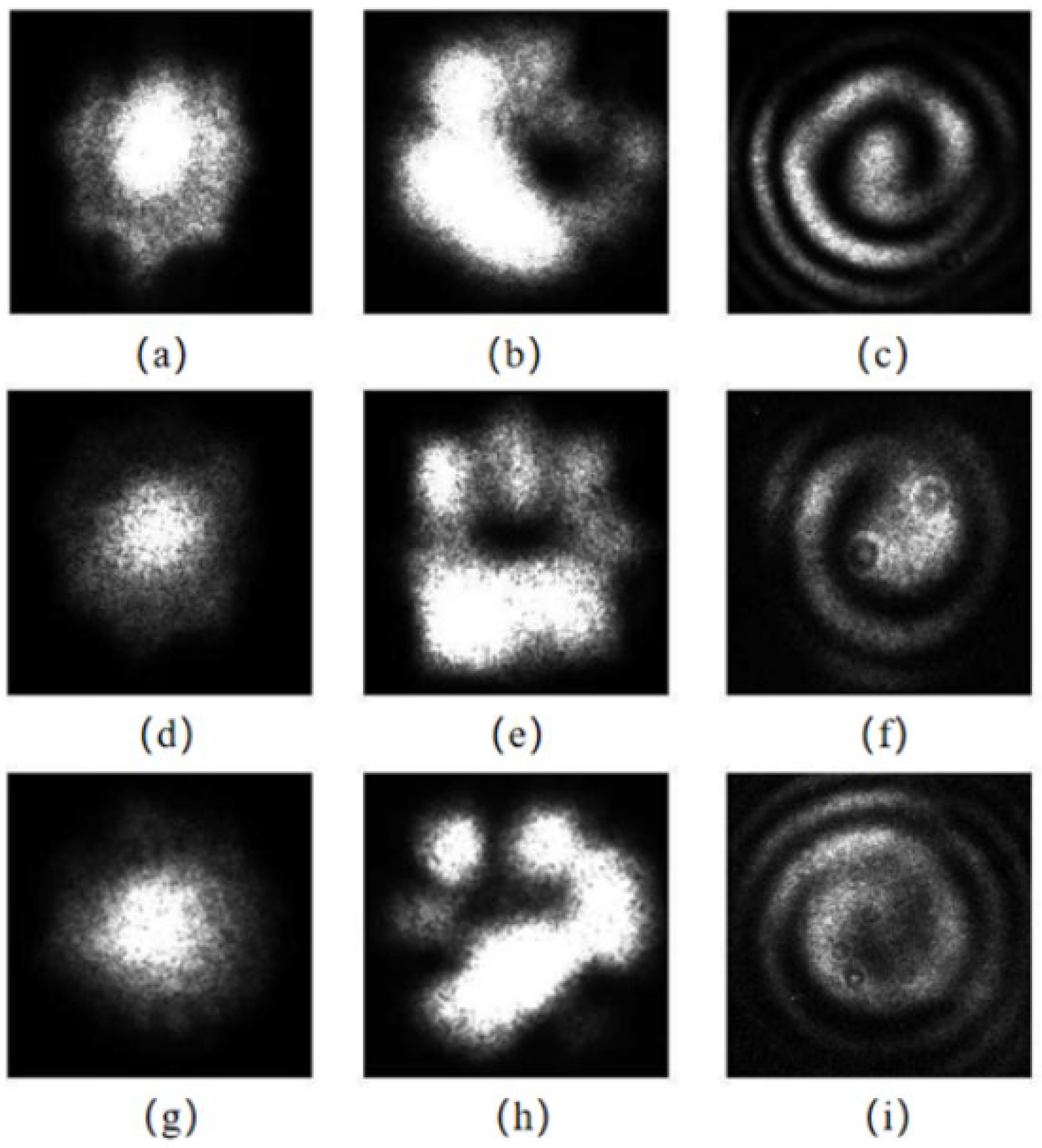
3.3.1. Chiral Twisted Photonics Crystal Fibers

CTPCF exhibits peculiar optical phenomena due to its unique air channel [48,49,50,55,57]. Under the influence of the spiral lattice in the air-hole channel, the cladding light in the PCF is limited to following a helical channel. This causes a portion of the axial momentum to be transferred to the azimuthal direction, resulting in a discrete orbital angular momentum [10]. When the arrangement of air holes and the twisting angle change, the topological phase of the core light and the degree of matching with the cladding leaky mode in terms of phase undergo changes, leading to the emergence of peculiar optical characteristics [56,58].
In 2012, Wong proposed the stimulation of OAM resonances in a twisted PCF; the twisted structure is shown in Figure 11. They investigated the transmission spectra and mode field states of CTPCF, laying the foundation for further research on CTPCF. Since then, further research has been conducted on generating and manipulating OAM using CTPCF. The effect of symmetry on the coupling between the core and cladding modes in a twisted PCF was analyzed [59]. By conducting numerical simulations on CTPCF fibers, they analyzed the impact of the cladding mode distribution on coupling. To further study the interaction between the core and cladding, Maciej introduced an analytical model describing the scaling properties of the CTMOFs [25,60]. They related the conditions of this coupling model to the wavelength, hole pitch, number of air holes, and twisted pitch. As a result, large loss peaks can be seen at various wavelengths. According to the above research, the generation of high-order OAM with CTMOF has sparked interest among researchers. Li reported a high-order mode suppression effect that could result in dips in the transmission spectrum of a six-core twisted microstructured fiber [61]. Cui demonstrated a helically twisted pig-nose-shaped core PCF for high-order OAM generation, as shown in Figure 12. In this fiber, the supermodes in the inner core are coupled to high-order modes in the outer ring core, generating ring-shaped OAM modes at different wavelengths and numerous OAM modes with various twist rates.
Apart from the generation of OAM, the underlying mechanism behind this new effect warrants further investigation. In coreless PCF, a twisted periodic structure generates a helical channel, allowing the production of guided modes without any recognizable core structure [54]. The mode field diameter decreases, and the refractive index increases as the twist rate increases. A twisted coreless PCF with helical Bloch modes (HBMs) was discovered, with each member exhibiting a distinct transverse field distribution and harmonic spectrum [62]. It is feasible to create a variety of high-index HBMs by constructing different stackings of air-hole structures. In 2023, Zeng reported the sustained oscillation of optical vortices and acoustic modes in a Brillouin laser based on a chiral PCF, which robustly supports HBMs that convey circularly polarized optical vortices and display circular birefringence, as shown in Figure 13. It uses a narrow-linewidth Brillouin fiber laser to emit steady first- and second-order vortex-carrying HBMs.
Due to its special circular birefringence effect, CTPCF has become a good choice for fiber optic sensors. The feasibility of CTPCF as a current sensor was verified by determining the CTPCF structure with the maximum circular birefringence via numerical analysis [51]. Additionally, the performance of the sensor was enhanced by altering the shape and scale parameters. In order to develop high-sensitivity sensors, a fabrication method of a helical photonic crystal fiber (HPCF) and an inflated HPCF (IHPCF) using an inflation-assisted hydrogen–oxygen flame heating technique [52] was proposed by Fu. The modifications of the air holes before and after are illustrated in Figure 14. Increasing the size of the air holes can significantly enhance transverse-load sensitivity. Ramya discovered that torsion can improve sensitivity when a sensor is used for salinity testing [53].

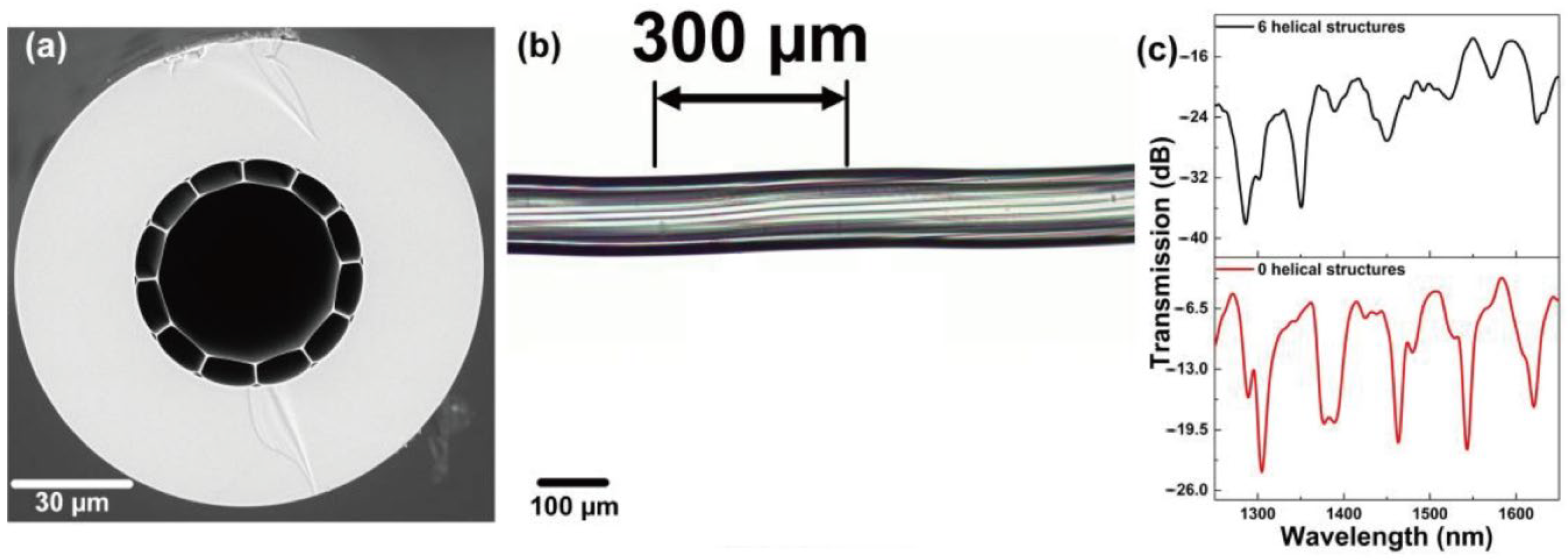
3.3.2. Chiral Twisted Hollow-Core Fibers

Hollow-core fiber [63,64], as its transmission medium is air, utilizes the transmission mechanism of bandgap or anti-resonance, resulting in extremely low dispersion, loss, and other characteristics. At the same time, its distinctive cladding distribution structure enables it to play an important role in various fields, such as transmission [65], amplification [66,67], lasers [68], and sensing [69]. When introducing a twist into the hollow-core fiber (HCF) [58,59,60,61,62,63,64,65,66,67,68,69,70,71,72], it can maintain strong circular birefringence and stable circular polarization characteristics [26,73]. In addition, further exploration and research are warranted for its unique optical effects, such as the hybrid photonic bandgap effect [74] and the generation and preservation of OAM modes [27,75].
Strong circular dichroism is an important characteristic of CTHCF. Roth demonstrated strong circular dichroism of HE11-like core mode in a helically twisted hollow-core single-ring photonic crystal fiber [76]. The refractive index vs. the azimuthal mode order is shown in Figure 15. When twisted, the ring exhibits significant circular birefringence, and one circular polarization state is allowed to couple into the core mode. The modulation and preservation of the circular polarization states are equally important. Davtyan presented a novel technique based on a twisted HCPCF, which exhibits circular birefringence and can thus maintain a circular polarization state even in the presence of external perturbations [21]. The method based on CTHCF has the potential to be applied to the generation, modulation, and transmission of circularly polarized light from ultraviolet to mid-infrared wavelengths.
CTHCF can also cause mode conversion into OAM modes, making it possible to create OAM modes using a straightforward and controllable method [75]. Tu investigated the OAM mode generation method for a long-period one-fold chiral fiber grating (L-1-CFG) based on an ARF [27]. They demonstrated that a first-order OAM mode can be generated simply by inputting a Gaussian light. The process of mode evolution is illustrated in Figure 16. Additionally, an appropriate twisted pitch can suppress the fundamental mode and maintain the purity of the higher-order modes [21]. This also provides a feasible solution for selecting specific modes.
The high robustness of HCF is also a major advantage in its applications. Compared to conventional HCF, CTHCF exhibits greater extinction ratio interference peaks, making it suitable for sensing applications. Zheng proposed a helical HCF for bending sensing [77]. In Figure 17, due to the isolation provided by the air gap, the bending sensitivity reaches −9.066 nm/m−1 while being minimally affected by external temperatures. Davtyan demonstrated a gas-filled helical SR-PCF that provides a potential platform for optical vortex excitation, excellent Raman frequency conversion, and strong polarization preservation, as well as low-loss guidance [78].

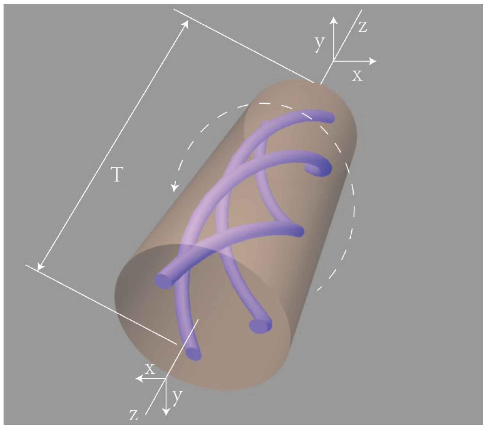
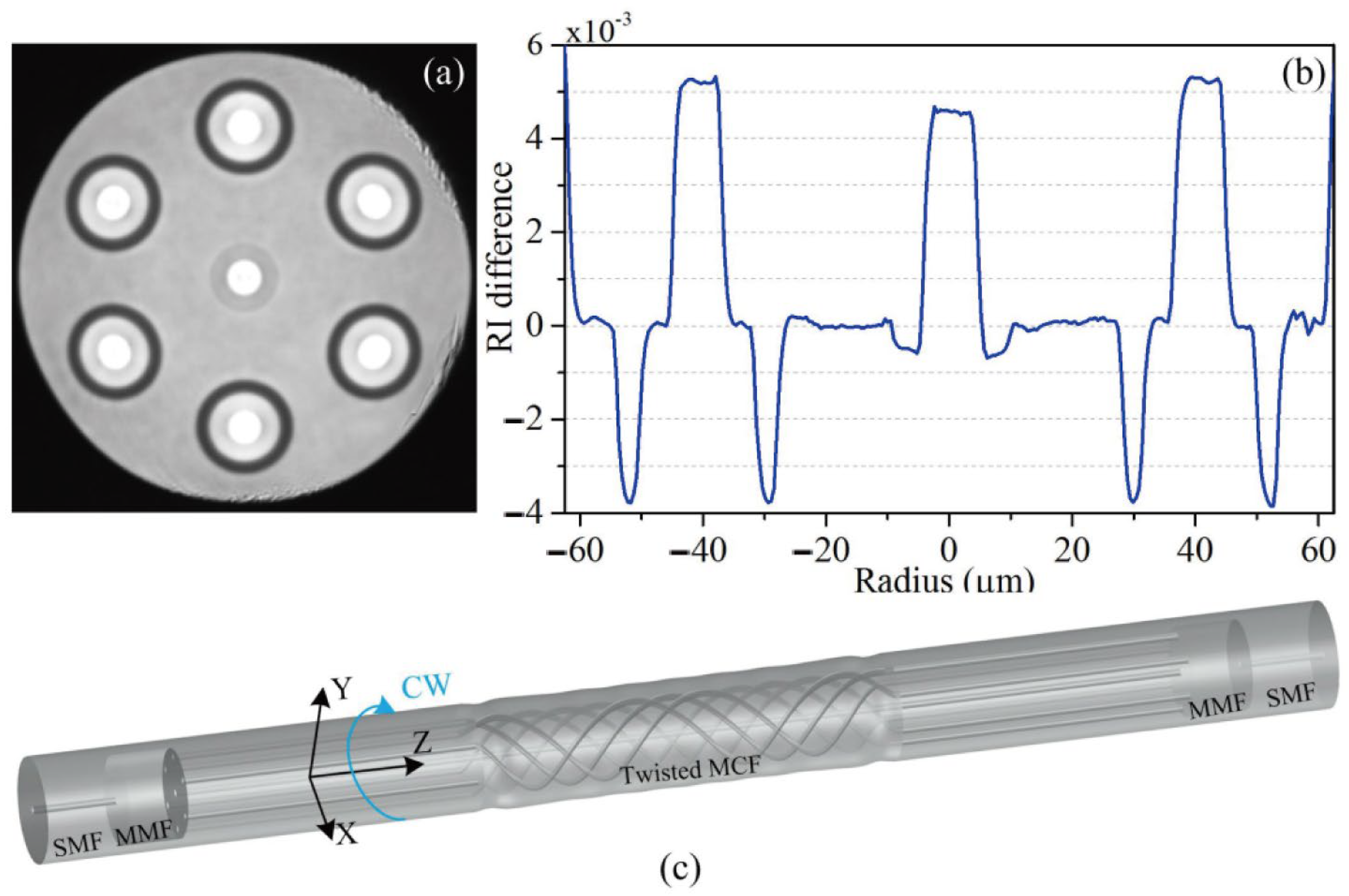
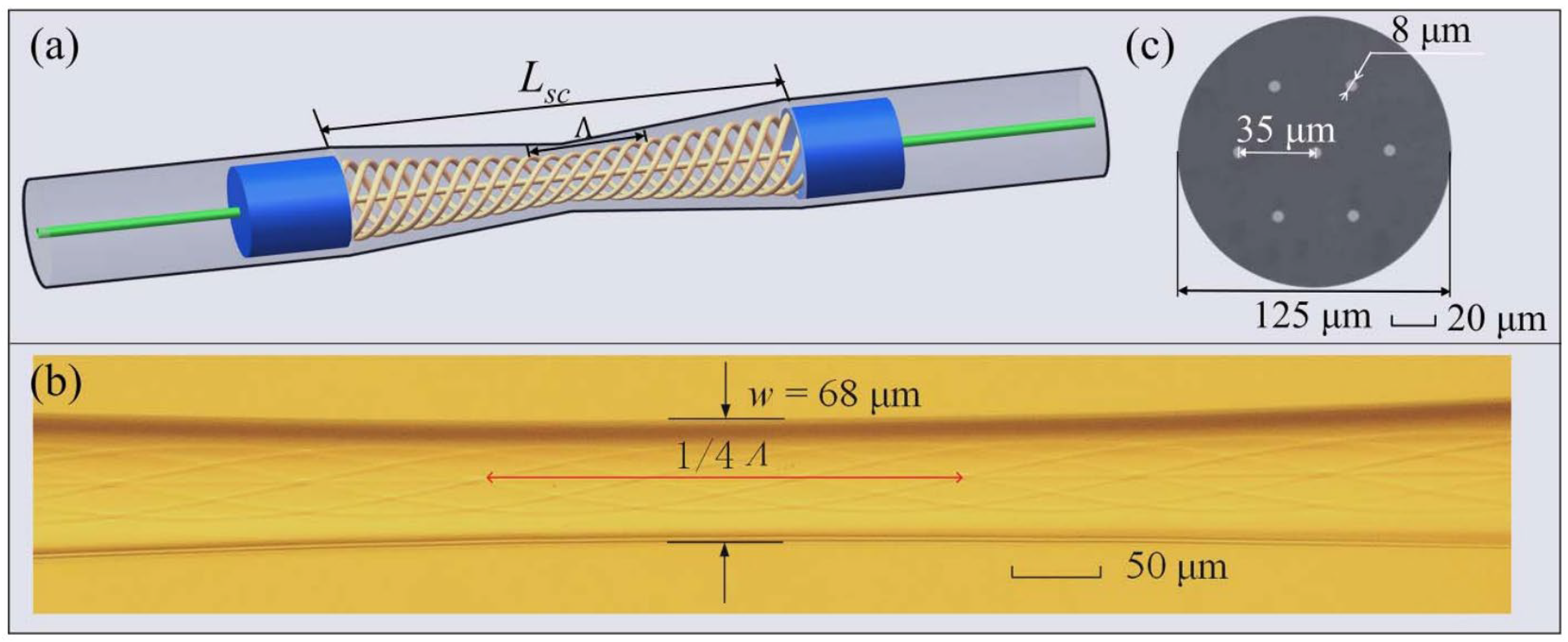
3.3.3. Chiral Twisted Multicore Fibers

Due to their ability to support multiple guided channels, multicore fibers have attracted researchers’ interest in the fields of transmission [79], amplification [80], and sensing [81,82]. CTMCF exhibits enhanced coupling between the fiber cores due to its helical structure [83], and its axial non-uniformity makes it outperform ordinary MCF in sensing [35,84], modulation of OAM modes [22], and other aspects.
The torsion sensor is an important application of CTHCF. Ordinary MCF can be used for torsion testing; however, it is unable to identify the torsion direction. In torsion measurement, the pitch length of a pre-twisted MCF changes with different directions of torsion. Therefore, CTHCF not only provides sensitivity in torsion testing but also allows for the determination of its direction [23,85,86,87,88]. Zhang proposed a directional torsion sensor based on a Mach–Zehnder interferometer (MZI) created in twisted multicore fibers (MCF) [84]. The cross-section of the multicore fiber and the sensor structure is shown in Figure 18. In addition to achieving circular fiber asymmetry using this short helical structure, multiple interferences were also significantly enhanced. The distinct interferences induced by the coupling between the center core, outer core, and cladding mode were shown by both the simulation and experimental spectrum analysis. The suggested sensor’s maximum torsion sensitivity is −0.118 nm/(rad/m), with twist rates between −17.094 rad/m and −15.669 rad/m. A highly sensitive strain sensor based on a twisted seven-core fiber is demonstrated [28]. To create an in-line MZI, a twisted structure was introduced in an all-solid seven-core fiber, and the twisted fiber was then spliced between two lengths of the multimode fibers. Because of its helical structure, a maximum strain sensitivity of 61.8 pm/με was reached. It is approximately 56 times greater than that of normal multicore MZI fiber sensors.
To further enhance the sensing performance of CTMCF, researchers are attempting some mechanical treatments of the fiber. Tapered multicore fibers can further enhance the coupling between cores, making it a promising method for enhancing sensitivity. In 2023, a directional torsion sensor based on an MZI in a tapered twisted seven-core fiber was proposed [11]. As shown in Figure 19, they investigated the sensing characteristics under different taper waists and different twisting periods. With a helical structure, the sensitivity reached 2.253 nm/(rad/m) and −1.123 nm/(rad/m). Furthermore, when the waist diameter was 48 m, the torsion sensitivity was 5.391 nm/(rad/m) by reducing the taper waist and increasing the density of the helix. They also calibrated the sensor’s temperature properties, and the sensitivity was attained at 32 pm/°C, which means that the tapered CTMCF can eliminate the cross-sensitivity to temperature. Song also demonstrated this characteristic of CTMCF via experimental verification [89]. Xiang utilized the CO2 laser method to fabricate an LPG from a twisted MCF, which also demonstrated low-temperature cross-sensitivity [29].
Adding functional materials to the CTMCF can further explore its potential applications. Liu attempted to coat gelatin on the surface of a four-core fiber (FCF) and deposited a gold coating on the end [30]. A twisted FCF was fabricated under a continuous arc discharge. When the humidity of the external environment changes, the refractive index and volume of the gelatin film also change, resulting in a shift in the resonance dip of the interference signal. Other functionalities can be achieved by modifying the core material of CTMCF instead of coating functional materials on the surface. CTMCF has been demonstrated to generate OAM modes [22]. Li replaced the core of the twisted multicore PCF with Yb-doped material (YTMF), as shown in Figure 20, to achieve the amplification of OAM light [14]. The experimental results show that the Yb3+ doped twisted fiber can be used for amplification at 1064 nm. In addition, theoretical research indicates that the amplified modes in YTMF at 1064 nm can support nine OAM modes. The results indicate that combining doped materials with CTMCF enables the generation, amplification, and multiplexing of multiple beams of OAM light, thereby providing new insights for the establishment of next-generation communication systems.

4. Summary and Outlook of Functional Chiral Twisted Fibers

Chiral twisted optical fibers introduce unusual optical phenomena by incorporating a special twisted structure into the fibers. We summarized the representative studies of different types of twisted fibers as functional devices, as shown in Table 1. The twisted structure in SMF induces changes in birefringence, allowing the twisted fibers to exhibit similar behavior to that of fiber gratings. When combined with MOFs, they exhibit unexpectedly excellent results in the generation and selection of OAM beams due to their circular polarization properties. They also exhibit robust birefringence towards OAM beams, meaning that modes with different principal OAM orders have non-degenerate propagation constants. Particularly in hollow-core fibers, CTMOFs exhibit exceptional performance in mode filtering and selection, indicating their potential for stable OAM transmission. Furthermore, the transmission spectra of CTMOFs exhibit wavelength-dependent attenuation based on the twisting pitch, making them suitable for sensing applications. These changes not only enhance the extinction ratio but also demonstrate significant advantages in directional discrimination. The combination of CTMOFs with functional materials expands their application scope, including external coating materials and internal core-doping materials.
Currently, the exploration of chiral twisted fibers is still in its early stages. First, the axial stability of the fibers prepared from CTMOF is a concern. During the process of heating and twisting the fibers, it may experience disturbances from arcs or lasers, causing radial perturbations and bending, in addition to the formation of periodic refractive index distributions along the axial direction. This can lead to unnecessary interference and increased transmission losses. In addition, although CTMOF has shown great potential for generating and transmitting OAM beams, the current fabrication methods are unable to meet the requirements for long-distance transmission, thus calling for more mature processes. Moreover, due to its versatile and intricate structure, CTMOF enables the transmission of higher-order OAM beams, thereby increasing its capacity. However, the transmission losses of higher-order mode beams are significant, which affects their practical applications. Furthermore, research on CTOMOF doped with multiple rare earths is currently limited. The circular birefringence and dispersion control of CTMOF in nonlinear optics and fiber lasers offer both opportunities and challenges for new types of mode-locked lasers, filters, and amplifiers. In the near future, these applications may be realized and applied to real-life engineering.

Author Contributions

Conceptualization, Y.Z., and B.L.; investigation, T.H., and G.Z.; writing—original draft preparation, Y.Z.; writing—review and editing, B.L., and G.Z.; visualization, Y.L.; funding acquisition, B.L. All authors have read and agreed to the published version of the manuscript.

Funding

This research was funded by the Basic and Applied Basic Research Foundation of Guangdong Province, China, grant number 2022A1515110480, 2022A1515140054.

Institutional Review Board Statement

Not applicable.

Informed Consent Statement

Not applicable.

Data Availability Statement

Data are available upon request due to restrictions, e.g., privacy or ethical concerns.

Conflicts of Interest

The authors declare no conflict of interest.

References

  1. Kopp, V.I.; Genack, A.Z. Chiral fibres: Adding twist. Nat. Photonics 2011, 5, 470–472. [Google Scholar] [CrossRef]
  2. Zhang, Y.; Zhang, W.; Wu, P.; Bie, L.; Kong, L.; Li, Z.; Zhang, Y.; Yan, T. Torsion bidirectional sensor based on tilted-arc long-period fiber grating. Opt. Express 2019, 27, 37695–37705. [Google Scholar] [CrossRef]
  3. Napiorkowski, M.; Urbańczyk, W. Rigorous modeling of twisted anisotropic optical fibers with transformation optics formalism. Opt. Express 2021, 29, 15199–15216. [Google Scholar] [CrossRef]
  4. Wang, X.; Deng, H.; Yuan, L. Highly Sensitive Flexible Surface Plasmon Resonance Sensor Based on Side-Polishing Helical-Core Fiber: Theoretical Analysis and Experimental Demonstration. Adv. Photonics Res. 2021, 2, 2000054. [Google Scholar] [CrossRef]
  5. Li, B.; Zhang, Y.; Zhou, G.; Hou, Z.; Xia, C. The Surface Plasmon Resonance Polarizing Management in Helical Microstructure Fiber. Plasmonics 2020, 15, 995–1000. [Google Scholar] [CrossRef]
  6. Zhao, H.; Wang, P.; Yamakawa, T.; Li, H. All-fiber second-order orbital angular momentum generator based on a single-helix helical fiber grating. Opt. Lett. 2019, 44, 5370–5373. [Google Scholar] [CrossRef]
  7. Zhao, Y.; Liu, S.; Luo, J.; Chen, Y.; Fu, C.; Xiong, C.; Wang, Y.; Jing, S.; Bai, Z.; Liao, C.; et al. Torsion, Refractive Index, and Temperature Sensors Based on an Improved Helical Long Period Fiber Grating. J. Light. Technol. 2020, 38, 2504–2510. [Google Scholar] [CrossRef]
  8. Wang, P.; Zhao, H.; Detani, T.; Tsuyuki, Y.; Li, H. Demonstration of the mode-selection rules obeyed in a single-helix helical long-period fiber grating. Opt. Lett. 2020, 45, 1846–1849. [Google Scholar] [CrossRef]
  9. Zeng, X.; Russell, P.S.; Chen, Y.; Wang, Z.; Wong, G.K.; Roth, P.; Frosz, M.H.; Stiller, B. Optical Vortex Brillouin Laser. Laser Photonics Rev. 2022, 17, 2200277. [Google Scholar] [CrossRef]
  10. Russell, P.S.; Beravat, R.; Wong, G.K. Helically twisted photonic crystal fibres. Philosophical transactions. Philos. Trans. Math. Phys. Eng. Sci. 2017, 375, 20150440. [Google Scholar]
  11. Wang, J.; Zeng, X.; Zhou, J.; Hao, J.; Yang, X.; Liu, Y.; Chen, W.; Li, S.; Yan, Y.; Geng, T.; et al. Highly sensitive torsion sensor based on Mach–Zehnder interference in helical seven-core fiber taper. Chin. Opt. Lett. 2023, 21, 041205. [Google Scholar] [CrossRef]
  12. Cui, M.; Mo, Z.; Zhao, N.; Xia, C.; Hou, Z.; Zhou, G. High-order orbital angular momentum generation in a helically twisted pig-nose-shaped core microstructured optical fibers. Opt. Express 2021, 29, 6542–6552. [Google Scholar] [CrossRef]
  13. Chattopadhyay, R.; Bhadra, S.K. Orbital Angular Momentum preserving guided mode in helically twisted hollow core photonic crystal fiber at Dirac point. arXiv 2019, arXiv:1902.09117. [Google Scholar]
  14. Li, B.; Zhou, G.; Liu, J.; Xia, C.; Hou, Z. Orbital-angular-momentum-amplifying helical vector modes in Yb3+-doped three-core twisted microstructure fiber. Opt. Express 2020, 28, 21110–21120. [Google Scholar] [CrossRef]
  15. Guo, Q.; Zhu, Y.; Shan, T.; Pan, X.; Liu, S.; Xue, Z.; Zheng, Z.; Chen, C.; Yu, Y. Intensity-modulated directional torsion sensor based on a helical fiber taper. Opt. Mater. Express 2020, 11, 80. [Google Scholar] [CrossRef]
  16. Yin, G.; Lu, L.; Zhou, L.; Shao, C.; Fu, Q.; Zhang, J.; Zhu, T. Distributed directional torsion sensing based on an optical frequency domain reflectometer and a helical multicore fiber. Opt. Express 2020, 28, 16140–16150. [Google Scholar] [CrossRef]
  17. Zhong, J.; Liu, S.; Zou, T.; Yan, W.; Chen, P.; Liu, B.; Sun, Z.; Wang, Y. High-Sensitivity Optical Fiber-Based Glucose Sensor Using Helical Intermediate-Period Fiber Grating. Sensors 2022, 22, 6824. [Google Scholar] [CrossRef]
  18. Zhu, T.; Chiang, K.S.; Rao, Y.; Shi, C.; Song, Y.; Liu, M. Characterization of Long-Period Fiber Gratings Written by CO2 Laser in Twisted Single-Mode Fibers. J. Light. Technol. 2009, 27, 4863–4869. [Google Scholar]
  19. Shin, W.; Yu, B.; Lee, Y.L.; Noh, Y.C.; Ko, D.; Lee, J. High strength coupling and low polarization-dependent long-period fiber gratings based on the helicoidal structure. Opt. Fiber Technol. 2008, 14, 323–327. [Google Scholar] [CrossRef]
  20. Sun, B.; Wei, W.; Liao, C.; Zhang, L.; Zhang, Z.; Chen, M.; Wang, Y. Automatic Arc Discharge-Induced Helical Long Period Fiber Gratings and Its Sensing Applications. IEEE Photonics Technol. Lett. 2017, 29, 873–876. [Google Scholar] [CrossRef]
  21. Edavalath, N.N.; Günendi, M.C.; Beravat, R.; Wong, G.K.; Frosz, M.H.; Ménard, J.; St. Russell, P.J. Higher-order mode suppression in twisted single-ring hollow-core photonic crystal fibers. Opt. Lett. 2017, 42, 2074–2077. [Google Scholar] [CrossRef] [PubMed]
  22. Zhang, Y.; Li, B.; Xia, C.; Hou, Z.; Zhou, G. Orbit angular momentum supermode in chirality helical dual-core microstructure fiber. Opt. Commun. 2020, 475, 126245. [Google Scholar] [CrossRef]
  23. Zhang, H.; Wu, Z.; Ping Shum, P.; Wah Low, C.; Shao, X.; Wang, R.; Quyen Dinh, X.; Fu, S.; Tong, W.; Tang, M. Simultaneous Measurement of Torsion and Temperature Based on Helical Structure in Multicore Fiber. In Proceedings of the 2016 Asia Communications and Photonics Conference (ACP), Wuhan, China, 2–5 November 2016. [Google Scholar]
  24. Wong, G.K.; Kang, M.S.; Lee, H.W.; Biancalana, F.; Conti, C.; Weiss, T.; Russell, P.S. Excitation of Orbital Angular Momentum Resonances in Helically Twisted Photonic Crystal Fiber. Science 2012, 337, 446–449. [Google Scholar] [CrossRef] [PubMed]
  25. Napiorkowski, M.; Renversez, G.; Urbańczyk, W. Effect of cladding geometry on resonant coupling between fundamental and cladding modes in twisted microstructured fibers. Opt. Express 2019, 27, 5447–5460. [Google Scholar] [CrossRef] [PubMed]
  26. Davtyan, S.; Novoa, D.; Chen, Y.B.; Frosz, M.H.; Russell, P.S. Polarization-Tailored Raman Frequency Conversion in Chiral Gas-Filled Hollow-Core Photonic Crystal Fibers. Phys. Rev. Lett. 2019, 122, 143902. [Google Scholar] [CrossRef]
  27. Tu, J.; Wu, J.; Huang, C.; Zhang, J.; Gao, S.; Liu, W.; Li, Z. OAM mode generation in helically twisted hollow-core antiresonant fiber. Opt. Lett. 2023, 48, 1634–1637. [Google Scholar] [CrossRef]
  28. Zhang, H.; Wu, Z.; Shum, P.P.; Dinh, X.Q.; Low, C.W.; Xu, Z.; Wang, R.; Shao, X.; Fu, S.; Tong, W.; et al. Highly sensitive strain sensor based on helical structure combined with Mach-Zehnder interferometer in multicore fiber. Sci. Rep. 2017, 7, 46633. [Google Scholar] [CrossRef]
  29. Xiang, S.; Xiongwei, H.; Luyun, Y.; Nengli, D.; Jianjun, W.; Fangfang, Z.; Jingang, P.; Haiqing, L.; Jinyan, L. Helical long-period grating manufactured with a CO2 laser on multicore fiber. Opt. Express 2017, 25, 10405–10412. [Google Scholar] [CrossRef]
  30. Liu, Y.; Zhou, A.; Yuan, L. Gelatin-Coated Michelson Interferometric Humidity Sensor Based on a Multicore Fiber with Helical Structure. J. Light. Technol. 2019, 37, 2452–2457. [Google Scholar] [CrossRef]
  31. Zhang, M.; Zhang, L.; Chen, Q.; Bai, G.; Li, S. A Designed Twist Sensor Based on the SPR Effect in the Thin-Gold-Film-Coated Helical Microstructured Optical Fibers. Sensors 2022, 22, 5668. [Google Scholar] [CrossRef]
  32. Li, C.; Xia, L.; Chen, X. Surface plasmon resonance effect in helical photonic crystal fiber using transformation optics formalism. In Proceedings of the 2017 25th Optical Fiber Sensors Conference (OFS), Jeju-Do, Republic of Korea, 24–28 April 2017. [Google Scholar]
  33. Deng, M.; Xu, J.; Zhang, Z.; Bai, Z.; Liu, S.; Wang, Y.; Zhang, Y.; Liao, C.; Jin, W.; Peng, G.; et al. Long period fiber grating based on periodically screw-type distortions for torsion sensing. Opt. Express 2017, 25, 14308–14316. [Google Scholar] [CrossRef] [PubMed]
  34. Bai, Z.; Wang, Y.; Zhang, Y.; Fu, C.; Liu, S.; Li, M.; Liao, C.; Wang, Y.; He, J. Helical Long-Period Fiber Gratings as Wavelength-Tunable Orbital Angular Momentum Mode Generators. IEEE Photonics Technol. Lett. 2020, 32, 418–421. [Google Scholar] [CrossRef]
  35. Xu, Y.; Lin, H.; Zhou, A. A Pre-Twisted Taper in Dual-Side Hole Fiber for Torsion Measurement with High Sensitivity. IEEE Sens. J. 2020, 20, 7761–7765. [Google Scholar] [CrossRef]
  36. Ulrich, R.; Simon, A. Polarization optics of twisted single-mode fibers. Appl. Opt. 1979, 18, 2241–2251. [Google Scholar] [CrossRef]
  37. Barlow, A.J.; Ramskov-Hansen, J.J.; Payne, D.N. Birefringence and polarization mode-dispersion in spun single-mode fibers. Appl. Opt. 1981, 20, 2962–2968. [Google Scholar] [CrossRef]
  38. Galtarossa, A.; Palmieri, L. Measure of twist-induced circular birefringence in long single-mode fibers: Theory and experiments. J. Light. Technol. 2002, 20, 1149–1159. [Google Scholar] [CrossRef]
  39. Tentori, D.; García-Weidner, A. Jones birefringence in twisted single-mode optical fibers. Opt. Express 2013, 21, 31725–31739. [Google Scholar] [CrossRef]
  40. Cao, X.; Tian, D.; Liu, Y.; Zhang, L.; Wang, T. Sensing Characteristics of Helical Long-Period Gratings Written in the Double-Clad Fiber by CO2 Laser. IEEE Sens. J. 2018, 18, 7481–7485. [Google Scholar] [CrossRef]
  41. Zhang, H.; Zhang, W.; Chen, L.; Xie, Z.; Zhang, Z.; Yan, T.; Wang, B. Bidirectional Torsion Sensor Based on a Pair of Helical Long-Period Fiber Gratings. IEEE Photonics Technol. Lett. 2016, 28, 1700–1702. [Google Scholar] [CrossRef]
  42. Xian, L.; Wang, D.; Li, L. Torsion and strain simultaneous measurement using a cascaded helical long-period grating. J. Opt. Soc. Am. B 2020, 37, 1307–1311. [Google Scholar] [CrossRef]
  43. Ivanov, O.V. Fabrication of long-period fiber gratings by twisting a standard single-mode fiber. Opt. Lett. 2005, 30, 3290–3292. [Google Scholar] [CrossRef] [PubMed]
  44. Li, B.; Xia, R.; Shum, P.P.; Zhou, G. Long-Period Gratings and Multimode Interference in Helical Single-Mode Fiber. IEEE Photonics Technol. Lett. 2019, 31, 1956–1959. [Google Scholar] [CrossRef]
  45. Nakano, S.; Fujisawa, T.; Saitoh, K. The Effect of Core Offset on the Mode Converting Characteristics in Twisted Single Mode Fibers. J. Light. Technol. 2019, 37, 5479–5485. [Google Scholar] [CrossRef]
  46. Liu, S.; Zhou, M.; Shao, L.; Zhang, Z.; Bai, Z.; Wang, Y. Torsion-tunable OAM mode generator based on oxyhydrogen-flame fabricated helical long-period fiber grating. Opt. Express 2022, 30, 21085–21093. [Google Scholar] [CrossRef] [PubMed]
  47. Wang, P.; Zhao, H.; Detani, T.; Li, H. Simultaneous Generation of the First- and Second- Order OAM Using the Cascaded HLPGs. IEEE Photonics Technol. Lett. 2020, 32, 685–688. [Google Scholar] [CrossRef]
  48. Fu, C.; Wang, Y.; Bai, Z.; Liu, S.; Zhang, Y.; Li, Z. Twist-direction-dependent orbital angular momentum generator based on inflation-assisted helical photonic crystal fiber. Opt. Lett. 2019, 44, 459–462. [Google Scholar] [CrossRef]
  49. Russell, P.S.; Chen, Y. Localization of Light in Multi-Helical Arrays of Discrete Coupled Waveguides. Laser Photonics Rev. 2022, 17, 2200570. [Google Scholar] [CrossRef]
  50. Zhang, S.; Liu, X.; Chen, L.; Zhang, C.; Bai, H.; Wu, J.; Shi, J.; Li, H.; Liu, Y. Wavelength Tunable Single-Circular-Polarization Twisted PCF. IEEE Photonics Technol. Lett. 2021, 33, 1355–1358. [Google Scholar] [CrossRef]
  51. Beravat, R.; Wong, G.K.; Xi, X.M.; Frosz, M.H.; St. Russell, P.J. Current sensing using circularly birefringent twisted solid-core photonic crystal fiber. Opt. Lett. 2016, 41, 1672–1675. [Google Scholar] [CrossRef]
  52. Fu, C.; Wang, Y.; Liu, S.; Bai, Z.; Tang, J.; Shao, L.; Liu, X. Transverse-load, strain, temperature, and torsion sensors based on a helical photonic crystal fiber. Opt. Lett. 2019, 44, 1984–1987. [Google Scholar] [CrossRef]
  53. Ramya, K.C.; Monfared, Y.E.; Maheswar, R.; Dhasarathan, V. Dual-Core Twisted Photonic Crystal Fiber Salinity Sensor: A Numerical Investigation. IEEE Photonics Technol. Lett. 2020, 32, 616–619. [Google Scholar] [CrossRef]
  54. Beravat, R.; Wong, G.K.; Frosz, M.H.; Xi, X.M.; Russell, P.S. Twist-induced guidance in coreless photonic crystal fiber: A helical channel for light. Sci. Adv. 2016, 2, e1601421. [Google Scholar] [CrossRef] [PubMed]
  55. Fujisawa, T.; Saitoh, K. Off-axis core transmission characteristics of helically twisted photonic crystal fibers. Opt. Lett. 2018, 43, 4935–4938. [Google Scholar] [CrossRef]
  56. Nakano, S.; Fujisawa, T.; Sato, T.; Saitoh, K. Beam propagation analysis of optical activity and circular dichroism in helically twisted photonic crystal fiber. Jpn. J. Appl. Phys. 2017, 57, 08PF06. [Google Scholar] [CrossRef]
  57. Churikov, V.M.; Kopp, V.I.; Genack, A.Z. Chiral diffraction gratings in twisted microstructured fibers. Opt. Lett. 2010, 35, 342–344. [Google Scholar] [CrossRef] [PubMed]
  58. Fujisawa, T.; Saitoh, K. Arbitrary polarization and orbital angular momentum generation based on spontaneously broken degeneracy in helically twisted ring-core photonic crystal fibers. Opt. Express 2021, 29, 31689–31705. [Google Scholar] [CrossRef]
  59. Napiorkowski, M.; Urbańczyk, W. Role of symmetry in mode coupling in twisted microstructured optical fibers. Opt. Lett. 2018, 43, 395–398. [Google Scholar] [CrossRef]
  60. Napiorkowski, M.; Urbańczyk, W. Scaling effects in resonant coupling phenomena between fundamental and cladding modes in twisted microstructured optical fibers. Opt. Express 2018, 26, 12131–12143. [Google Scholar] [CrossRef]
  61. Li, J.; Li, B.; Xia, C.; Hou, Z.; Zhou, G. High order modes suppression and manipulation in six-holes helical chiral microstructure fiber. Opt. Fiber Technol. 2021, 61, 102445. [Google Scholar] [CrossRef]
  62. Roth, P.; Wong, G.K.; Frosz, M.H.; Ahmed, G.; Russell, P.S. Full-field characterization of helical Bloch modes guided in twisted coreless photonic crystal fiber. Opt. Lett. 2019, 44, 5049–5052. [Google Scholar] [CrossRef]
  63. Hong, Y.; Gao, S.; Ding, W.; Zhang, X.; Jia, A.; Sheng, Y.; Wang, P.; Wang, Y. Highly Birefringent Anti-Resonant Hollow-Core Fiber with a Bi-Thickness Fourfold Semi-Tube Structure. Laser Photonics Rev. 2022, 16, 2100365. [Google Scholar] [CrossRef]
  64. Gao, S.; Wang, Y.; Ding, W.; Hong, Y.; Wang, P. Conquering the Rayleigh Scattering Limit of Silica Glass Fiber at Visible Wavelengths with a Hollow-Core Fiber Approach. Laser Photonics Rev. 2019, 14, 1900241. [Google Scholar] [CrossRef]
  65. Michaud-Belleau, V.; Numkam Fokoua, E.R.; Bradley, T.D.; Hayes, J.R.; Chen, Y.; Poletti, F.; Richardson, D.J.; Genest, J.; Slavík, R. Backscattering in antiresonant hollow-core fibers: Over 40 dB lower than in standard optical fibers. Optica 2021, 8, 216–219. [Google Scholar] [CrossRef]
  66. Belardi, W.; Sazio, P.J.; Bigot, L. Hollow core fibers for optical amplification. Opt. Lett. 2019, 44, 4127–4130. [Google Scholar] [CrossRef] [PubMed]
  67. Yang, F.; Gyger, F.; Thévenaz, L. Intense Brillouin amplification in gas using hollow-core waveguides. Nat. Photonics 2020, 14, 700–708. [Google Scholar] [CrossRef]
  68. Nampoothiri, A.V.; Jones, A.M.; Fourcade-Dutin, C.; Mao, C.; Dadashzadeh, N.; Baumgart, B.; Wang, Y.; Alharbi, M.; Bradley, T.D.; Campbell, N.S.; et al. Hollow-core Optical Fiber Gas Lasers (HOFGLAS): A review [Invited]. Opt. Mater. Express 2012, 2, 948–961. [Google Scholar] [CrossRef]
  69. Förster, R.; Weidlich, S.; Nissen, M.; Wieduwilt, T.; Kobelke, J.; Goldfain, A.M.; Chiang, T.K.; Garmann, R.F.; Manoharan, V.N.; Lahini, Y.; et al. Tracking and analysing the Brownian motion of nano-objects inside hollow core fibers. ACS Sens. 2020, 5, 879–886. [Google Scholar] [CrossRef]
  70. Stefani, A.; Fleming, S.C.; Kuhlmey, B.T. Terahertz orbital angular momentum modes with flexible twisted hollow core antiresonant fiber. APL Photonics 2017, 3, 051708. [Google Scholar] [CrossRef]
  71. Xie, S.; Sharma, A.; Romodina, M.N.; Joly, N.Y.; Russell, P.S. Tumbling and anomalous alignment of optically levitated anisotropic microparticles in chiral hollow-core photonic crystal fiber. Sci. Adv. 2021, 7, eabf6053. [Google Scholar] [CrossRef]
  72. Stefani, A.; Lwin, R.; Argyros, A.; Fleming, S. Hollow-Core Antiresonant Fibers with a Twist. In Proceedings of the Australian Conference on Optical Fibre Technology, Sydney, Australia, 5–8 September 2016. [Google Scholar]
  73. Guerra, G.; Mousavi, S.M.; Taranta, A.; Fokoua, E.R.; Santagiustina, M.; Galtarossa, A.; Poletti, F.; Palmieri, L. A method to compute the local birefringence vector in twisted and bent antiresonant hollow-core fibers. In Proceedings of the 2023 Optical Fiber Communications Conference and Exhibition (OFC), San Diego, CA, USA, 5–9 March 2023. [Google Scholar]
  74. Zhu, Y.; Li, W.; Gao, F.; Xu, X.; Song, N. Hybrid photonic bandgap effect in twisted hollow-core photonic bandgap fibers. Opt. Lett. 2022, 47, 6161–6164. [Google Scholar] [CrossRef]
  75. Stefani, A.; Kuhlmey, B.T.; Fleming, S.C. Orbital angular momentum modes by twisting of a hollow core antiresonant fiber. In Proceedings of the 2017 Conference on Lasers and Electro-Optics Europe and European Quantum Electronics Conference (CLEO/Europe-EQEC), San Jose, CA, USA, 14–19 May 2017. [Google Scholar]
  76. Roth, P.; Chen, Y.; Günendi, M.C.; Beravat, R.; Edavalath, N.N.; Frosz, M.H.; Ahmed, G.; Wong, G.K.; Russell, P.S.J. Strong circular dichroism for the HE 11 mode in twisted single-ring hollow-core photonic crystal fiber. Optica 2018, 5, 1315–1321. [Google Scholar] [CrossRef]
  77. Zheng, Y.; Shum, P.P.; Li, B.; Zhang, H.; Auguste, J.; Humbert, G. Experimental Investigation of Bending Sensor Based on Helical Structure in Hollow Core Fiber. In Proceedings of the 2020 IEEE Photonics Conference (IPC), Vancouver, BC, Canada, 28 September–1 October 2020. [Google Scholar]
  78. Davtyan, S.; Chen, Y.B.; Frosz, M.H.; St. Russell, P.J.; Novoa, D. Robust excitation and Raman conversion of guided vortices in a chiral gas-filled photonic crystal fiber. Opt. Lett. 2020, 45, 1766–1769. [Google Scholar] [CrossRef]
  79. Puttnam, B.J.; Rademacher, G.; Luís, R.S. Space-division multiplexing for optical fiber communications. Optica 2021, 8, 1186–1203. [Google Scholar] [CrossRef]
  80. Jain, S.; Castro, C.; Jung, Y.; Hayes, J.R.; Sandoghchi, R.; Mizuno, T.; Sasaki, Y.; Amma, Y.; Miyamoto, Y.; Bohn, M.; et al. 32-core erbium/ytterbium-doped multicore fiber amplifier for next generation space-division multiplexed transmission system. Opt. Express 2017, 25, 32887–32896. [Google Scholar] [CrossRef]
  81. Meng, Y.; Fu, C.; Du, C.; Chen, L.; Zhong, H.; Li, P.; Xu, B.; Du, B.; He, J.; Wang, Y. Shape Sensing Using Two Outer Cores of Multicore Fiber and Optical Frequency Domain Reflectometer. J. Light. Technol. 2021, 39, 6624–6630. [Google Scholar] [CrossRef]
  82. Zhou, R.; Chen, F.; Li, S.; Wang, R.; Qiao, X. Three-Dimensional Vector Accelerometer Using a Multicore Fiber Inscribed with Three FBGs. J. Light. Technol. 2021, 39, 3244–3250. [Google Scholar] [CrossRef]
  83. Sakamoto, T.; Aozasa, S.; Mori, T.; Wada, M.; Yamamoto, T.; Nozoe, S.; Sagae, Y.; Tsujikawa, K.; Nakajima, K. Twisting-Rate-Controlled 125 μm Cladding Randomly Coupled Single-Mode 12-Core Fiber. J. Light. Technol. 2018, 36, 325–330. [Google Scholar] [CrossRef]
  84. Zhang, H.; Wu, Z.; Shum, P.P.; Shao, X.; Wang, R.; Dinh, X.Q.; Fu, S.; Tong, W.; Tang, M. Directional torsion and temperature discrimination based on a multicore fiber with a helical structure. Opt. Express 2018, 26, 544–551. [Google Scholar] [CrossRef]
  85. Parker, R.; Aceves, A. Standing-wave solutions in twisted multicore fibers. Phys. Rev. A 2021, 103, 053505. [Google Scholar] [CrossRef]
  86. Zhang, X.I.A.O.; Vysloukh, V.A.; Kartashov, Y.V.; Chen, X.; Ye, F.; Belić, M.R. PT symmetry in nonlinear twisted multicore fibers. Opt. Lett. 2017, 42, 2972–2975. [Google Scholar] [CrossRef]
  87. Suchkov, S.V.; Chekhovskoy, I.S.; Shtyrina, O.V.; Wabnitz, S.; Fedoruk, M.P. Nonlinear twisted multicore fibers with PT-symmetry. Opt. Commun. 2023, 530, 129147. [Google Scholar] [CrossRef]
  88. Khan, F.; Barrera, D.; Sales, S.; Misra, S. Curvature, twist and pose measurements using fiber Bragg gratings in multi-core fiber: A comparative study between helical and straight core fibers. Sens. Actuators 2021, 317, 112442. [Google Scholar] [CrossRef]
  89. Song, Z.; Li, Y.; Hu, J. Directional Torsion Sensor Based on a Two-Core Fiber with a Helical Structure. Sensors 2023, 23, 2874. [Google Scholar] [CrossRef] [PubMed]
Figure 1. Illustration of twisted single-core fiber at different positions in the optical fiber. (a) The core is located at the axis of the fiber, forming an HLPG structure. (b) The core is away from the fiber axis, and the partially bent core mode is converted into cladding WGMs.
Photonics 10 01025 g001
Figure 2. Schematic diagram of the twistedmicrostructured optical fiber, where the purple tubes represent the cores, and the dashed arrow indicates the direction of twisting.
Photonics 10 01025 g002
Figure 3. Methods for fabricating a helical optical fiber. (a) Hydrogen–oxygen flame method [17]. (b) CO2 laser beam method [19]. (c) Automatic arc discharge technology [20].
Photonics 10 01025 g003
Figure 4. Spatial optical interference method for characterizing the twisted fiber [19]. (a) Common experimental setup for verifying OAM light. (be) The interference results of the OAM beams generated by twisted fiber.
Photonics 10 01025 g004
Figure 5. The spectral analysis method used for characterizing the optical properties of twisted fiber [35].
Photonics 10 01025 g005
Figure 6. The change in the output polarization state with varying twist angles was observed for both erbium-doped fiber (a) and standard single-mode fiber (b), and it was characterized using Stokes parameters (S1, S2, S3) [39].
Photonics 10 01025 g006
Figure 7. The periodic variation of the core refractive index forms LPG, which results in two distinct interference dips appearing in the transmission spectrum. The interference of internal harmonics also generates small dips in certain sections, as indicated by the green arrows [44].
Photonics 10 01025 g007
Figure 8. Torsion and strain measurement by using a cascaded HLPG [42].
Photonics 10 01025 g008
Figure 9. Schematic of the ccHLPGs-based OAM generator [47].
Photonics 10 01025 g009
Figure 10. The evolution of mode field distributions and their interference patterns with the Gaussian beams with varying torsion angles [46].
Photonics 10 01025 g010
Figure 11. Helically twisted PCF and local axial and azimuthal refractive index components of the fundamental space-filling Bloch mode in twisted cladding [24].
Photonics 10 01025 g011
Figure 12. (a) Cross-section and sketch of the HPC-MOF. (b) The overall structure of the twisted HPC-MOF [12].
Photonics 10 01025 g012
Figure 13. Experimental setup of vortex Brillouin laser [9].
Photonics 10 01025 g013
Figure 14. SEM photos of the cross-sections of the obtained HPCF and IHPCF [52].
Photonics 10 01025 g014
Figure 15. Modal refractive index vs. azimuthal mode order for (a) untwisted and (b) twisted SR-PCFs in the first Brillouin zone. The allowed azimuthal mode orders are marked with circles and represented between the gray-dashed areas in the diagram [76].
Photonics 10 01025 g015
Figure 16. (a,d,g) Input modes, (b,e,h) output modes, and (c,f,i) interference patterns of CTHCF [27].
Photonics 10 01025 g016
Figure 17. (a) Cross-section of HCF. (b) Illustration of the twisted HCF. (c) HCF transmission spectra with and without twisted structures [77].
Photonics 10 01025 g017
Figure 18. (a) Cross-section image of the seven-core fiber. (b) Refractive index of the proposed fiber. (c) The diagram of the sensor structure prepared by twisting the seven-core fiber along the direction of the blue arrow [84].
Photonics 10 01025 g018
Figure 19. (a) Schematic of the tapered twisted fiber; (b) structure of the twisted fiber sensor structure; (c) cross-section of the MCF [11].
Photonics 10 01025 g019
Figure 20. (a) Cross-section diagram of the YTMF; (b) twisted machining diagram; (c) lateral view of the twist sample [14].
Photonics 10 01025 g020
Table 1. Comparison table of different types of optical fibers with twisted structures.
Fiber TypeFabricationFunctionYearRef.
SMFCO2 laserLPG and mode interference2019[44]
SMFCO2 laserTorsion and strain sensor2020[42]
SMFHydrogen–oxygen flameOAM generator2022[46]
PCFCO2 laserOAM resonances2012[24]
PCFHydrogen–oxygen flameMultiparameter sensor2019[52]
PCFTheoretical researchHigh-order OAM generation2021[12]
PCFCO2 laserVortex Brillouin laser2023[9]
HCFDuring fiber drawingStrong circular dichroism2018[76]
HCFAutomatic arc dischargeBending sensor2020[77]
HCFAutomatic arc dischargeOAM mode generation2023[27]
MCFCO2 laserTorsion sensor2018[84]
MCFCO2 laserOAM amplifier2020[14]
MCFAutomatic arc dischargeTorsion sensor2023[11]
Disclaimer/Publisher’s Note: The statements, opinions and data contained in all publications are solely those of the individual author(s) and contributor(s) and not of MDPI and/or the editor(s). MDPI and/or the editor(s) disclaim responsibility for any injury to people or property resulting from any ideas, methods, instructions or products referred to in the content.

