Article

Imaging through a Scattering Medium under Different Intensities of Ambient Light Interference

1
Fujian Science and Technology Innovation Laboratory for Optoelectronic Information of China, Fuzhou 350108, China
2
The College of Computer and Cyber Security, Fujian Normal University, Fuzhou 350117, China
3
Quanzhou Institute of Equipment Manufacturing, Fujian Institute of Research on the Structure of Matter, Chinese Academy of Sciences, Quanzhou 362216, China
4
School of Advanced Manufacturing, Fuzhou University, Quanzhou 362000, China
*
Author to whom correspondence should be addressed.
Photonics 2023, 10(9), 1023; https://doi.org/10.3390/photonics10091023
Submission received: 21 July 2023 / Revised: 19 August 2023 / Accepted: 24 August 2023 / Published: 7 September 2023

Abstract

:
Many solutions for imaging through a scattering medium are sensitive to noise, which can lead to degradation or even to a failure of the image quality. This is especially the case in practical application scenarios, which are always filled with changing ambient light interference; as such, the traditional methods are difficult to practically apply. Therefore, in this paper, a spatial-frequency dual-domain learning neural network is designed for reconstructing the target of a speckle pattern under different intensities of ambient light interference. The network is mainly based on two modules. One module is designed from two perspectives, frequency domain denoising and the spatial-frequency spectrum of the speckle pattern. Another module is a dual-feature fusion attention module, which is used to improve the accuracy of the network. The experimental results demonstrate that the network is capable of reconstructing complex targets with high quality under varying intensities of interfering light. Furthermore, it is not constrained by the optical memory effect, exhibiting remarkable robustness and generalizability. The research based on this paper provides a feasible path for the practical application of scattering imaging methods.

1. Introduction

A scattering medium or rough surfaces cause light to scatter, thus distorting the information carried by the light and making it difficult to observe and detect objects. Imaging through a scattering medium is a challenging problem in many fields, involving nondestructive testing, autonomous driving, biological tissues, etc. Therefore, accurate imaging in a scattering medium has high scientific value and application prospects. To solve this challenge, researchers have proposed and developed many scattering imaging techniques to solve the issue, ranging from the wavefront shaping of scattered light [1,2,3], transmission matrix measurements [4,5], the speckle autocorrelation technique [6,7], spectroscopic analysis of multiple scattered light [8], to angular domain imaging [9], etc. However, these techniques are often sensitive to external noise, which can come from aspects such as the camera, dust, imaging distance, and ambient light. Among these factors, ambient light interference is one of the most important factors affecting the performance of imaging algorithms. This is especially the case in industrial production with complex and changeable environments, where it is easy to cause a degradation in the imaging effects, and even a failure in the reconstruction process. Therefore, overcoming interfering light is a key issue in the practical application of scattering medium imaging technology, which needs further research and solutions.
To solve this problem, Li et al. used the Zernike polynomial-based method and the improved low-rank and sparse decomposition technique to separate the strong background noise from the speckle autocorrelation, and then utilized the phase retrieval algorithm for target reconstruction [10]. Niu’s team used the singular value decomposition for the removal of ambient light noise, as well as to improve the contrast of speckle autocorrelations; then, they introduced an additional guiding point in the object plane, through which they indirectly reconstructed the target from the speckle autocorrelation [11]. Ma et al. proposed a plug-and-play algorithm based on the generalized alternating projection optimization framework; this was then combined with neural networks and the Fienup phase retrieval method fo the purposes of recovering the imaging through a scattered medium in disturbed environments [12]. Cheng et al. used speckle autocorrelation information, as physical constraints, and deep learning to propose a two-stage neural network for background light denoising and object reconstruction [13]. The above studies were all based on the nature of speckle autocorrelation, whereby the imaging field of view is limited and most of the imaging quality is not high.
As a data-driven algorithm, deep learning has been widely used in many fields, such as computer vision, natural language processing, autonomous driving, etc., with its powerful representation in learning ability and its high generalization ability. In the field of optics, the application of deep learning has also received increasing attention and has shown great potential. At present, deep learning has been successfully applied to solve problems in the field of computational imaging such as phase imaging [14], super-resolution imaging [15], and polarization imaging [16]. Therefore, using deep learning to solve some optical problems is a particularly promising method.
Deep learning is currently used for imaging through a scattering medium, generally for target reconstruction, and mainly in the original spatial domain. However, under complex noise conditions, learning only through the spatial domain leads to the problem of insufficient detail enhancement in the reconstructed target, which reduces the contrast and signal-to-noise ratio of the reconstructed image (or even reconstruction failure). In this work, we refer to frequency domain denoising and the spatial frequency spectrum of the speckle pattern to propose SFM—a joint spatial and frequency domain learning module that extracts more features and details from the complex background optical noise. DFFAM, a dual-feature fusion attention module was also constructed so as to improve the accuracy of the network. The network based on these two modules not only reconstructs the target under different levels of ambient light interference, but also has a good recovery capability for more complex targets. Based on the model for imaging through a scattered medium, there is no need to be limited by the optical memory effect (OME); in addition, the network has good robustness and generalization.

2. Principles and Methods

2.1. Physical Principles

The speckle autocorrelation technique is one of the most important solutions for imaging through a scattered medium, and it is characterized by non-invasive and fast imaging. Based on the speckle autocorrelation theory, the relationship between the speckle pattern and object is expressed as per the following equation [17] (whereby the Fourier transform of speckle autocorrelation is equal to the speckle power spectral density by Wiener Sinchen’s theorem [18]):
I I = ( O S ) ( O S ) = ( O O ) ( S S ) = ( O O ) + C = F F T 1 | F F T { I } | 2
where the symbol ★ is the autocorrelation operation; ∗ is the convolution operation; I and O denote the camera-captured speckle pattern and the spatial-domain target, respectively; S denotes the PSF; C is the background noise; and F F T and F F T 1  denote the Fourier transform and inverse Fourier transform, respectively.
Based on the above formula, the speckle autocorrelation can be obtained. In the case of no interfering light, the traditional algorithm uses some phase retrieval algorithms to recover the target from speckle autocorrelation. For example, HIO [19], ADMM-based [20], and prGAMP [21]. But these algorithms take a long time to calculate, and the accuracy of reconstruction for the target is not high.
Especially as ambient light interference gradually intensifies (as manifested by the increasing factor C in Equation (1)), the complexity of factor C also increases. Intricate noise further hinders the accuracy of valuable information. Consequently, researchers often use Singular Value Decomposition (SVD), Zernike polynomials, and Fourier transformation techniques to separate interference noise from the speckle autocorrelation signal. Then, a phase retrieval algorithm reconstructs the target. While these methods partially isolate the noise components, they do not fully eliminate residual noise. This deficiency could result in inadequate reconstruction quality. Furthermore, these algorithms are limited by OME.
Meanwhile, the speckle autocorrelation technique generally employes an incoherent light source. This choice is based on the principle that higher incoherence results in a closer resemblance between the autocorrelation of the speckle pattern and that of the object itself [17]. As the coherence of the light source increases, interference among different point spread functions arises, contributing to speckle contrast and subsequently intensifying the complexity of image reconstruction [22]. However, even under coherent light irradiation conditions, the spatial frequencies of the object remain well preserved within the spatial frequency spectrum of the speckle pattern [23].
Building upon the aforementioned concepts, it is valuable to explore the information in the speckle frequency domain under conditions of coherent or incoherent light. Therefore, in this paper, we utilize the powerful learning capabilities of deep learning to fuse the frequency domain information of speckle with its spatial domain, creating a neural network model that addresses the limitation of the speckle autocorrelation technique in the presence of ambient light interference.

2.2. Module Design and Network Framework

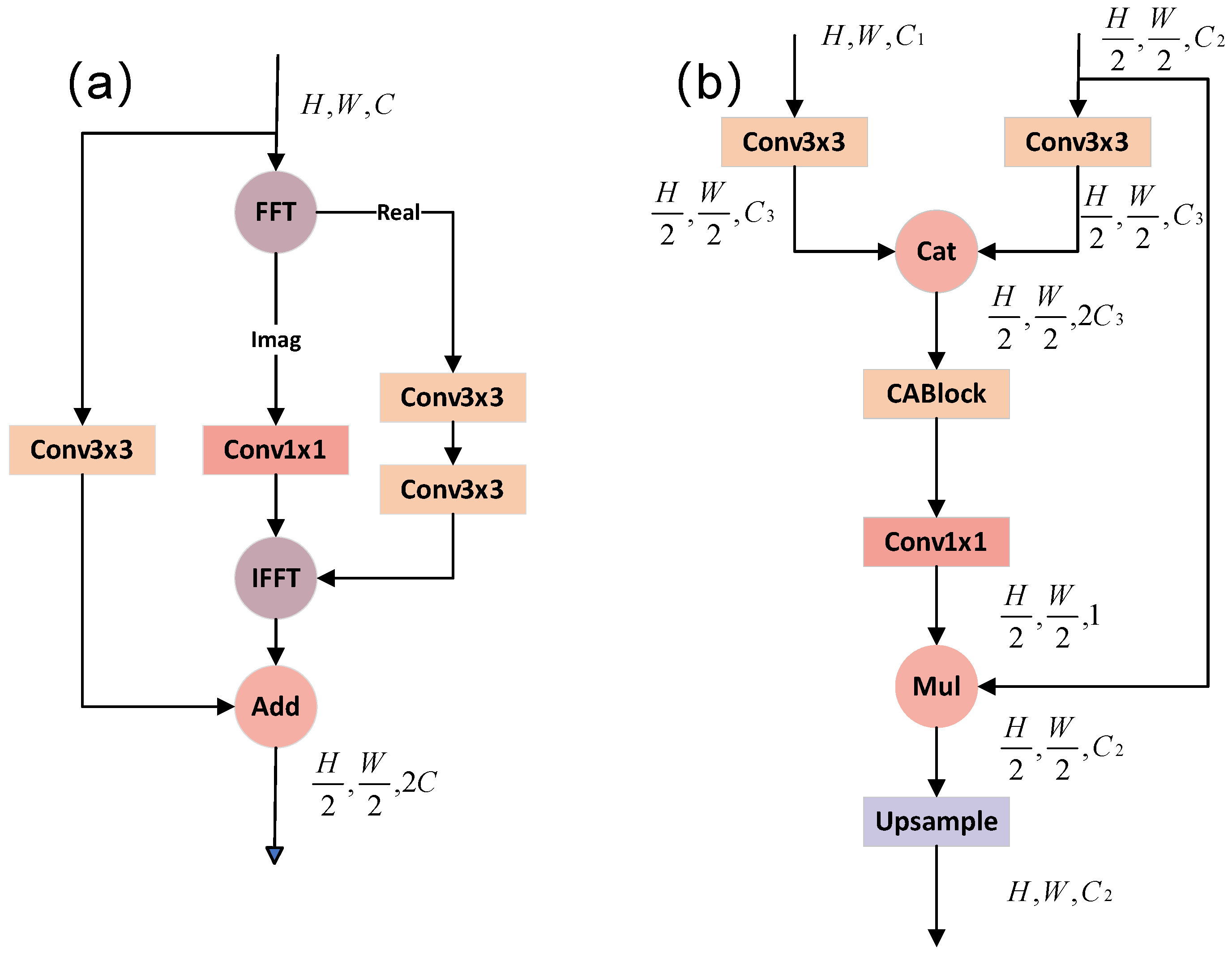
2.2.1. SFM and DFFAM
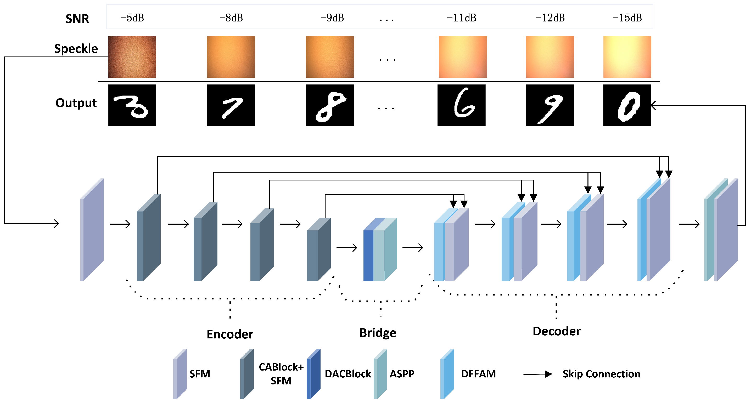
Based on the above principle, the frequency domain information of the speckle pattern implies the spatial frequency details of the object, regardless of whether it is under conditions of coherent or incoherent light. Simultaneously, we consider the frequency domain denoising perspective. We embed the process of Fourier transform into the neural network, and utilize the powerful feature extraction capability of deep learning to extract information and learn directly from the frequency domain, and also learn features from the spatial domain. Learning from two dimensions can enhance the denoising and learning ability of the network. Therefore, we propose the spatial frequency dual-domain joint learning module, SFM. The structure of the SFM is shown in Figure 1a.
The structure of the SFM is divided into two parts. One part is the spatial domain part which performs feature extraction learning on the input feature map through a 3 × 3 convolutional block. The other part is the frequency domain part. In this part, first the Fourier transform is performed on the feature map to generate the spectrogram, the real part of which is extracted for feature extraction learning and the imaginary part of which is dimensionally transformed using a convolutional block with a convolutional kernel of 1 × 1. After the feature extraction in the frequency domain, the frequency feature is switched to the spatial domain by using the inverse Fourier transform. The features learned in the spatial and frequency domains are then summed to obtain a richer and more integrated feature representation. The module helps to improve the representation and performance of the model.
To further improve the accuracy and generalization ability of the model, we also design a dual-feature fusion attention module, DFFAM, which is designed to suppress non-correlated regions in the input feature maps during the up-sampling process while highlighting specific local regions of salient features to improve the accuracy of the model prediction. The module structure is shown in Figure 1b.
This module has two input branches. One input is the feature map from the encoder and the other is the feature map obtained from the previous layer decoder. First, the feature fusion of the two is performed to generate a new feature map in which channel attention and positional pixel attention are computed by using CABlock [24]. It is then dimensionally transformed using a convolutional block with a convolutional kernel of 1 × 1, and ultimately becomes a weight matrix with a channel number of 1. The weight matrix is finally multiplied with the feature map obtained from the previous layer decoder and is used to highlight the useful information in the previous layer decoder’s feature map and to inhibit the useless information to increase the network accuracy.

2.2.2. Model Design

Based on the two modules of SFM and DFFAM, we design a network that can not only recover the image of the speckle pattern under different intensities of interference light, but also reconstruct complex objects with good quality. The proposed model consists of several encoders and decoders. Each encoder consists of a CABlock and an SFM. The CABlock is a channel and position attention mechanism. Although the speckle image is disordered, the adjacent pixels all have a certain relationship and a certain degree of redundancy [25]. By introducing the position attention mechanism, the information of the speckle can be well extracted and the accuracy of the network can be improved. The DACBlock [26] module and the ASPP [27] module are used as a bridge between the encoder and decoder, because ASPP and DACBlock can capture contextual information, provide multi-scale information, and have good results in various visual tasks. The decoder consists of DFFAM and SFM. The specific network is shown in Figure 2.
The network input is speckle patterns under ambient light interference of different intensities with a speckle pattern size of 256 × 256. The input first passes through an encoder stage for multiple downsampling. After downsampling, it passes through the bridging module for multi-scale information extraction. It then enters the decoder stage, which performs multiple upsampling. Each upsampling connects the output of the previous module with the output of the respective encoder after residual concatenation prior to feature extraction and learning. After upsampling, the final output of the 256 × 256 prediction map is passed through the network header.
For network training, we use D S S I M [28] as the loss function of the network. The expression is as follows:
L o s s = D S S I M = 1 S S I M ( X , Y ) 2 ,
S S I M ( X , Y ) = 1 2 u X u Y + c 1 2 σ X Y + c 2 u X 2 + u Y 2 + c 1 σ X 2 + σ Y 2 + c 2 ,
where Y denotes the predicted image; X denotes the real image; u X and u Y denote the mean of X and Y, respectively; σ X 2 and σ Y 2 are the variances of images X and Y, respectively; σ X Y is the covariance of the X and Y, and c 1 , c 2 denote the stabilizing constant.
In the experiment, the signal-to-noise ratio ( S N R ) is utilized to measure the ratio of the intensity of the target signal to the intensity of the ambient light, which is calculated by formula
S N R x 0 , x p = 10 × l o g 10 x 0 x p .
In the formula, x 0 and x p represent the light intensity measured by the light meter without ambient light interference and the light intensity measured when the ambient light intensity is p. In general, the lower the ambient light interference, the higher the S N R , the better the image quality, and vice versa.
To quantitatively evaluate the imaging performance of the model, the structural similarity S S I M and the root mean square error, R M S E , are used to measure its imaging quality; S S I M is up to 1. The higher the image quality, the better; the lower the R M S E , the better the image quality. The formula of R M S E is as follows.:
R M S E ( X , Y ) = 1 N i = 1 n X i Y i 2 .
Here, Y represents the predicted image, X represents the real image, N represents the total number of image pixels, and i represents the ith pixel.

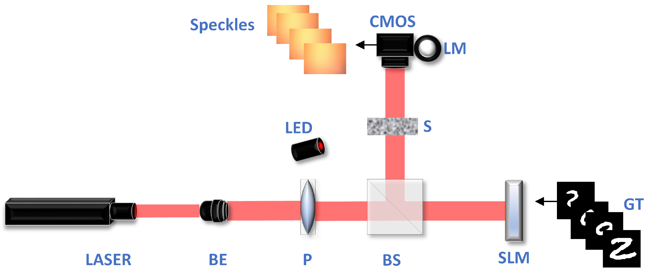
2.3. Measurement System

To demonstrate the effectiveness of our approach, we test the proposed model by acquiring real optical datasets using the optical path system shown in Figure 3. A laser (LR-TRL-635, CHANGCHUN LASER TECHNOLOGY) with a wavelength of 635 nm is used as the light source to generate a Gaussian beam. The Gaussian beam is expanded by a beam expander, then the expanded beam is passed through a horizontal polarizer and is split into two parts by a beam splitter. One part of the beam is incident upon the reflective phase-only SLM (PLUTO, Holoeye), the pixel size of which is 8.0 μm. We sample all target objects to 256 × 256 and then load them into the SLM. After the beam is reflected by the SLM, it carries the corresponding object information. After that, the beam is scattered through the scattering medium (Ground Glass Diffuser, 220grid, GCL-201101, DHC), and the distance from the SLM to the scattering medium is 30 cm. Finally, the scattered light is captured by an industrial camera (BFS-U3-123S6CC, FILR) to record the speckle pattern, and the pixel size of the camera is 3.45 μm, and the distance from the scattering medium to the CMOS is 10 cm. During data acquisition, an LED (GCI-060411, DHC) with adjustable light intensity is placed next to the scattering medium as an interfering light source, and the light emitted from the LED either enters the camera indirectly through the scattering medium, or enters the camera directly. We adjust the light intensity of the LED step by step from minimum to maximum to obtain the speckle pattern under different interference intensities and use a light meter (ZTW1701A, CHNT) to measure the intensity value of the current ambient light during recording.
To fully evaluate our proposed network, we load different types of images into the SLM, all of which are grayscale. First, the speckle patterns of MNIST handwritten digits under different ambient light intensities are captured, with a total of 9 different interference intensities, increasing irregularly from 0 lux to 1200 lux, where 1200 lux is the maximum light intensity emitted from the LEDs measured by the light meter at a fixed position. The light intensity of the light source before reaching the camera is measured to be 40 lux with no interference from the ambient light, so that the SNR of the maximum interference intensity is calculated to be −15 dB. A total of 1000 speckle patterns are available for each interference light intensity; the first 900 images are used as the training set of the network and the last 100 images are used as the validation set. Second, the FASHION dataset is collected, with a total of 5 groups of different interfering light intensities, each with 1000 speckle patterns, and the same 0.9:0.1 ratio is used to divide the dataset. This dataset is collected to evaluate the universality of the network’s imaging. Finally, to validate that the method is free from the limitation of the OME, a double-digit dataset is constructed based on the MNIST handwritten digits. The double-digit dataset has a total of 9 groups of 1000 images each. The model is trained and tested in Pytorch version 1.12 under Ubuntu 16.04. The hardware specifications of the workstation are two NVIDIA GeForce 3090RTX devices and an Intel Core i9-10990X central processor.

3. Results and Discussion

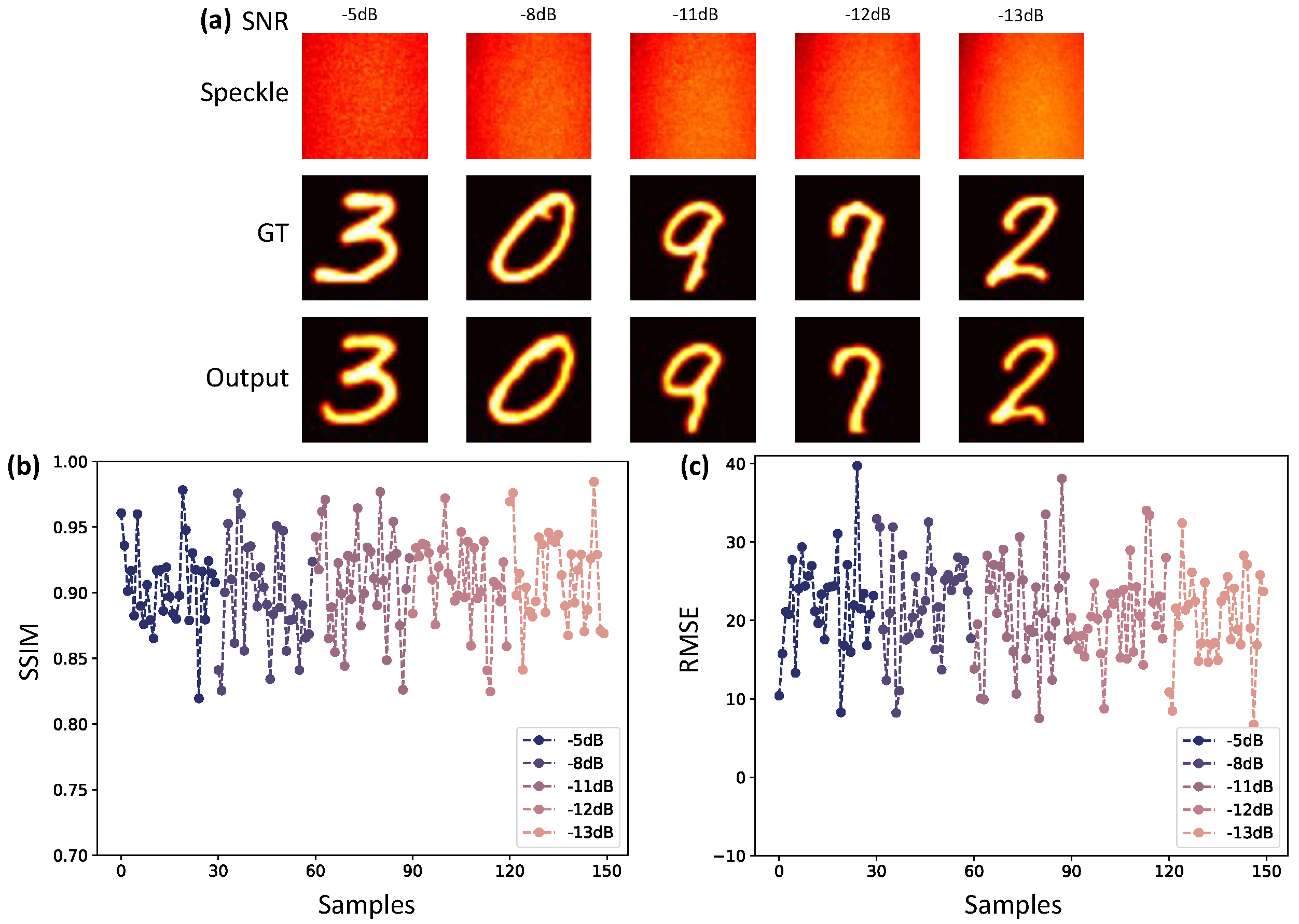
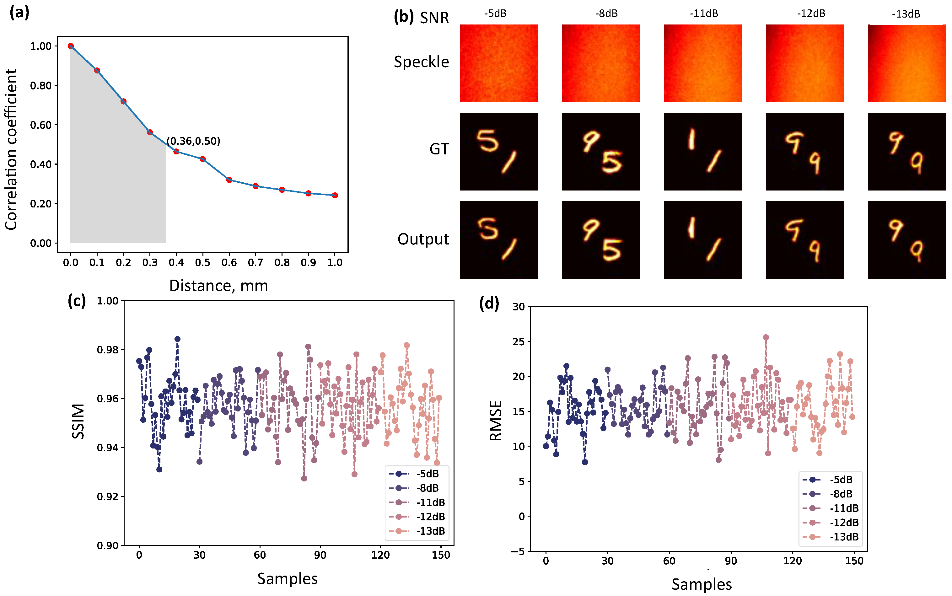
3.1. Imaging Recovery under Different Interference Intensities

In this study, we assess the network’s accuracy by examining five groups of speckle patterns generated under varying interference intensities. These groups exhibit SNRs of −5 dB, −8 B, −11 dB, −12 dB, and −13 dB. The image type is MNIST handwritten digits. The network is first trained and then evaluated with a validation set. The final result of the network is shown in Figure 4.
Figure 4a is a sample display of speckle imaging recovery under different ambient light interference by the network, including speckle images under different SNR values, and examples of their corresponding real labels and prediction results. It can also be seen that the imaging accuracy of the network through the scattering medium under different intensities of interfering light shows good performance. To more accurately represent the accuracy of the network, we randomly select 30 samples from the validation set of each group of speckle patterns under different interference intensities for prediction. To quantitatively evaluate the image quality, we adopt SSIM and RMSE as evaluation metrics. Figure 4b,c display the image quality evaluation of the validation outcomes. It is evident that the model exhibits fluctuations in the target reconstruction accuracy for each group. The optimal SSIM for each group can exceed 0.96, while the optimal RMSE can drop to approximately 7.0. On the other hand, the poorest SSIM within each group can fall below 0.83, and the highest RMSE can reach 40.0 or higher. The average accuracy of each validation set is very similar, with their average SSIM as high as 0.91 and average RMSE as low as 21.3.
To enhance the evaluation of the network’s performance, we conduct experiments by training other neural networks using the same training dataset. Specifically, we employ three conventional networks, namely UNet, NestedUNet, and ResUNet++. We compare the outcomes obtained from these networks with the outcomes achieved by the network proposed by us.
Table 1 presents the comparative results, providing a quantitative assessment of the networks’ performance. The evaluation metrics used for this analysis are SSIM and RMSE. The table displays the performance of these networks in relation to the accuracy of the entire validation set. Our analysis of the results reveals that the network designed in this paper exhibits superior accuracy in terms of both SSIM and RMSE when compared to the conventional networks. The quantitative data presented in Table 1 provides further evidence to support our observation and underscores the improved performance of the proposed network in terms of overall validation set accuracy.

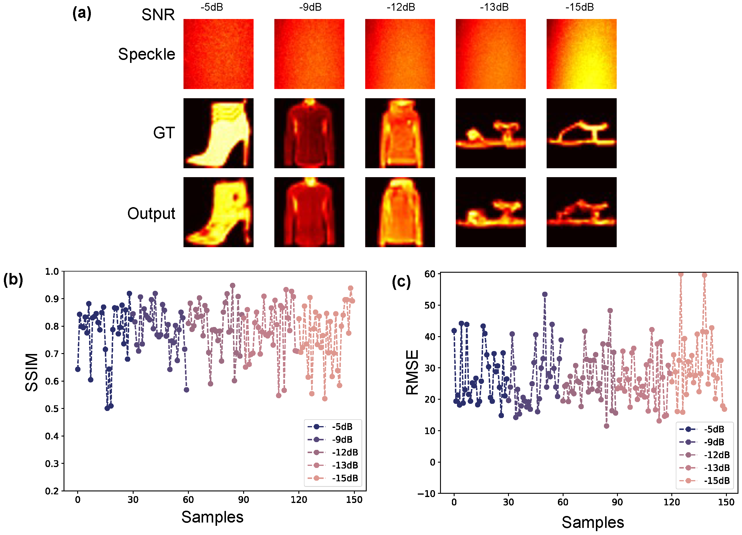
3.2. Complex Target Imaging under Different Interference Intensities

To demonstrate that the designed network is capable of reconstructing targets with high quality in the absence of the OME or outside the field of view of the OME, we chose coherent light as the light source and measure the OME range of the system. We refer to the method in the references to measure the OME range [32,33,34]. First, we place a 5 × 5 pixel square on the object plane. At 0.02 mm intervals, the relative position between the square and the scattering medium is slightly changed using a displacement stage. The final correlation coefficient curve is shown in Figure 5a, so the effective radius of the OME range of our system is measured to be 0.36 mm. Based on the effective radius of the OME range and the SLM pixel size, the OME range of the SLM on this system is 90 × 90 pixels. Thus, as long as the width and height of the non-zero portion of our dataset is larger than 90 pixels, we can demonstrate that our network is not affected by OME when reconstructing the target.
Based on the measured range of OME, we chose a double-digit dataset to load into the SLM, with a two-digit size larger than 90 pixels. We use the two-digit dataset to capture several groups of speckle patterns under different ambient light intensities. We select five datasets to train the network, and their SNRs are −5 dB, −8 dB, −11 dB, −12 dB, and −13 dB, respectively.The training results are shown in Figure 5.
As shown in Figure 5b, the network consistently maintains good accuracy for the double-digit dataset under different ambient light intensities. As can be seen from Figure 5c,d, among the randomly selected samples, SSIM has the highest target reconstruction accuracy of 0.98 with a low RMSE of 8.0, while the worst SSIM stays above 0.92 with the highest RMSE of about 26. In addition, the average sum of accuracies for these five validation sets is also very good, with the average SSIM and the average RMSE values of 0.96 and 15.8, respectively. Thus, the network designed by us continues to exhibit excellent imaging quality when reconstructing complex targets in complex scenes without the limitation of OME.
To further test that the model can still be effective in more complex scenes, we use the FASHION dataset with more complex target shapes and more disordered gray distributions to train the network with a wider range of SNRs. It also does not satisfy the condition of the OME. In the dataset collected by the experiment, there are a total of five groups with different interference intensities, and their SNRs are −5 dB, −9 dB, −12 dB, −13 dB, −15 dB, respectively. After training the network, the results of these five groups of validation sets are shown in Figure 6.
From Figure 6, it can be seen that the network designed in this paper still has good accuracy for the reconstruction of complex targets in complex scenes. Especially from Figure 6b,c, it can be seen that the network has high accuracy for most of the targets reconstruction, and the maximum SSIM of single sample accuracy can be as high as 0.94, and the minimum RMSE can be as low as 11.0. While the reconstruction accuracy for some more complex targets is not high, with SSIM as low as 0.5 and RMSE as high as 60.0. In this paper, we first argue that this happens because the original complex target has a complex pixel distribution. Second, even if the target is sampled from 28 × 28 pixels to 256 × 256 pixels when it is loaded into the SLM, its pixel details are still severely lost after passing through the optical path system. Especially when imaging through a scattering medium, some particularly complex details are indeed difficult to recover. Overall, however, the overall accuracy of SSIM for the five validation sets is as high as 0.77 and the RMSE is as low as 28.7, indicating that the network still maintains a certain degree of effectiveness when dealing with images of more complex shapes.

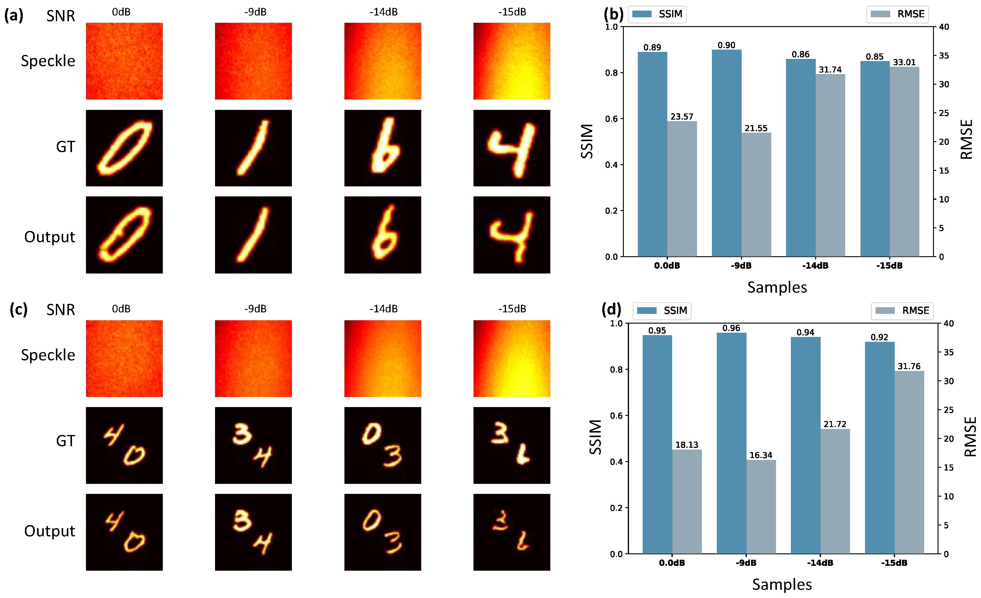
3.3. Network Robustness and Generalization

To evaluate the network’s generalizability and assess its resistance to interference, we choose two distinct datasets: MNIST handwritten digits and double-digit images. These datasets are used to examine how well the network can generalize and maintain its performance under varying conditions. The network is trained with five sets of speckle patterns for each dataset type. The SNRs of these five sets of speckle patterns are −5 dB, −8 dB, −11 dB, −12 dB, and −13 dB, respectively. The network trained with these five groups is employed to predict the validation sets of the additional four groups, which are not included in the network’s training process, and their respective SNRs are 0 dB, −9 dB, −14 dB, and −15 dB. The reconstruction accuracies of the validation sets for these two types of datasets are illustrated in Figure 7.
As depicted in Figure 7, it is evident that the network maintains a certain level of quality in reconstructing the respective four groups of untrained speckle patterns, both for the MNIST handwritten digits and double-digit images. Within the trained intensity range and without trained interference intensity, SNR = −9 dB, the accuracy of the validation set remains comparable to that achieved with the trained speckle patterns. For the interference intensity below the trained intensity range (SNR = 0 dB), the overall target reconstruction accuracy remains acceptable, albeit with a slightly lower validation set SSIM. As for the interference intensity above the trained intensity range (SNR = −14 dB and SNR = −15 dB), the network is still capable of reconstruction to a certain extent. However, it is worth noting that our reconstruction accuracy gradually decreases as the ambient light intensity increases. It is worth emphasizing that, even under the challenging SNR = −15 dB condition where the information is significantly masked by ambient light, the designed network can still extract valid information and achieve effective reconstruction. This performance surpasses the reconstruction accuracy of the physical method. Therefore, from the above analysis, it can be seen that the network can sufficiently learn from the existing dataset and reconstruct the dataset without training and beyond the interference range, indicating that the network is resistant to interference and possesses strong generalization and robustness.

4. Conclusions

In this paper, we draw on the frequency domain denoising principle and the spatial frequency spectrum of the speckle pattern to design the SFM to retrieve the hidden target and spatial information more easily. This is conducive to the further popularization of the scattering imaging technique in practical applications. We also design DFFAM to improve the model perception and prediction performance for complex scenes. The network, designed by combining these two modules, can perform intricate target reconstruction using a single speckle pattern, addressing the challenge of recovering scattering imaging data under varying ambient light intensities. Notably, this network showcases exceptional generalization and robustness, even in the presence of intricate ambient light fluctuations. It is not constrained by the OME and maintains strong performance in reconstructing complex targets, even at a SNR as low as −15 dB. In future research endeavors, we intend to further refine these two modules and the network structure to tackle even more complex scenes and objects. Additionally, we aim to explore their applicability in other computational imaging tasks, such as phase imaging, computational ghost imaging, and image super-resolution.

Author Contributions

Conceptualization, Y.Z.; methodology, Y.Z.; software, Y.Z. and R.L.; validation, Y.Z., Y.Y. and R.L.; formal analysis, Y.Z. and H.H.; investigation, Y.Z.; resources, F.W. and H.H.; data curation, F.W. and H.H.; writing—original draft preparation, Y.Z.; writing—review and editing, H.H. and J.H.; visualization, Y.Z. and Y.Y.; supervision, H.H. and J.H.; funding acquisition, J.H. All authors have read and agreed to the published version of the manuscript.

Funding

This research is funded in part by the External Cooperation Program of Chinese Academy of Sciences under Grant 121835KYSB20180062, Fujian Science and Technology Innovation Laboratory for Optoelectronic Information under Grant 2021ZR107; Fujian Provincial Science and Technology Project Fund under Grants 2021T3060, 2021T3032 and 2022T3068. Quanzhou Science and Technology Project Fund under Grant 2022C009R.

Institutional Review Board Statement

Not applicable.

Informed Consent Statement

Not applicable.

Data Availability Statement

Data underlying the results presented in this paper are not publicly available at this time but may be obtained from the authors upon reasonable request.

Conflicts of Interest

The authors declare no conflict of interest.

References

  1. Galaktionov, I.; Nikitin, A.; Samarkin, V.; Sheldakova, J.; Kudryashov, A.V. Laser beam focusing through the scattering medium-low order aberration correction approach. In Unconventional and Indirect Imaging, Image Reconstruction, and Wavefront Sensing; SPIE: San Diego, CA, USA, 2018; Volume 10772, pp. 259–272. [Google Scholar] [CrossRef]
  2. Katz, O.; Small, E.; Silberberg, Y. Looking around Corners and through Thin Turbid Layers in Real Time with Scattered Incoherent Light. Nat. Photonics 2012, 6, 549–553. [Google Scholar] [CrossRef]
  3. Paudel, H.P.; Stockbridge, C.; Mertz, J.; Bifano, T. Focusing polychromatic light through scattering media. In Mems Adaptive Optics VII; SPIE: San Diego, CA, USA, 2013; Volume 8617, pp. 82–88. [Google Scholar] [CrossRef]
  4. Popoff, S.M.; Lerosey, G.; Carminati, R.; Fink, M.; Boccara, A.C.; Gigan, S. Measuring the Transmission Matrix in Optics: An Approach to the Study and Control of Light Propagation in Disordered Media. Phys. Rev. Lett. 2010, 104, 100601. [Google Scholar] [CrossRef] [PubMed]
  5. Tripathi, S.; Paxman, R.; Bifano, T.; Toussaint, K.C. Vector Transmission Matrix for the Polarization Behavior of Light Propagation in Highly Scattering Media. Opt. Express 2012, 20, 16067–16076. [Google Scholar] [CrossRef] [PubMed]
  6. Bertolotti, J.; Van Putten, E.G.; Blum, C.; Lagendijk, A.; Vos, W.L.; Mosk, A.P. Non-Invasive Imaging through Opaque Scattering Layers. Nature 2012, 491, 232–234. [Google Scholar] [CrossRef] [PubMed]
  7. Lu, D.; Feng, Y.; Peng, X.; He, W. Speckle Autocorrelation Separation for Multi-Target Scattering Imaging. Opt. Express 2023, 31, 6529–6539. [Google Scholar] [CrossRef]
  8. Matthews, T.E.; Medina, M.; Maher, J.R.; Levinson, H.; Brown, W.J.; Wax, A. Deep tissue imaging using spectroscopic analysis of multiply scattered light. Optica 2014, 1, 105–111. [Google Scholar] [CrossRef]
  9. Pfeiffer, N.; Chapman, G.H.; Kaminska, B. Optical imaging of structures within highly scattering material using an incoherent beam and a spatial filter. In Optical Interactions with Tissues and Cells XXI; SPIE: San Diego, CA, USA, 2010; Volume 7562, pp. 33–43. [Google Scholar] [CrossRef]
  10. Li, W.; Xi, T.; He, S.; Liu, L.; Liu, J.; Liu, F.; Wang, B.; Wei, S.; Liang, W.; Fan, Z. Single-Shot Imaging through Scattering Media under Strong Ambient Light Interference. Opt. Lett. 2021, 46, 4538–4541. [Google Scholar] [CrossRef]
  11. Niu, Y.; Gao, Z.; Zhao, J.; Deng, L.; Sa, Y.; Wang, S. An Improving Method of Imaging through Scattering Medium under Strong Background Illumination. Measurement 2023, 210, 112548. [Google Scholar] [CrossRef]
  12. Ma, K.; Wang, X.; He, S.; Li, L. Plug-and-Play Algorithm for Imaging through Scattering Media under Ambient Light Interference. Opt. Lett. 2023, 48, 1754–1757. [Google Scholar] [CrossRef]
  13. Cheng, Q.; Guo, E.; Gu, J.; Bai, L.; Han, J.; Zheng, D. De-Noising Imaging through Diffusers with Autocorrelation. Appl. Opt. 2021, 60, 7686–7695. [Google Scholar] [CrossRef]
  14. Lin, H.; Huang, C.; He, Z.; Zeng, J.; Chen, F.; Yu, C.; Li, Y.; Zhang, Y.; Chen, H.; Pu, J. Phase Imaging through Scattering Media Using Incoherent Light Source. Photonics 2023, 10, 792. [Google Scholar] [CrossRef]
  15. Li, W.; Abrashitova, K.; Osnabrugge, G.; Amitonova, L.V. Generative Adversarial Network for Superresolution Imaging through a Fiber. Phys. Rev. Appl. 2022, 18, 034075. [Google Scholar] [CrossRef]
  16. Lin, B.; Fan, X.; Li, D.; Guo, Z. High-Performance Polarization Imaging Reconstruction in Scattering System under Natural Light Conditions with an Improved U-Net. Photonics 2023, 10, 204. [Google Scholar] [CrossRef]
  17. Katz, O.; Heidmann, P.; Fink, M.; Gigan, S. Non-invasive single-shot imaging through scattering layers and around corners via speckle correlations. Nat. Photonics 2014, 8, 784–790. [Google Scholar] [CrossRef]
  18. Fienup, J.R. Phase Retrieval Algorithms: A Personal Tour [Invited]. Appl. Opt. 2013, 52, 45. [Google Scholar] [CrossRef] [PubMed]
  19. Fienup, J.R. Phase Retrieval Algorithms: A Comparison. Appl. Opt. 1982, 21, 2758–2769. [Google Scholar] [CrossRef]
  20. Chang, J.; Wetzstein, G. Single-Shot Speckle Correlation Fluorescence Microscopy in Thick Scattering Tissue with Image Reconstruction Priors. J. Biophotonics 2018, 11, e201700224. [Google Scholar] [CrossRef] [PubMed]
  21. Schniter, P.; Rangan, S. Compressive Phase Retrieval via Generalized Approximate Message Passing. IEEE Trans. Signal Process. 2015, 63, 1043–1055. [Google Scholar] [CrossRef]
  22. Goodman, J.W. Speckle Phenomena in Optics: Theory and Applications; Roberts and Company Publishers: Greenwood Village, CO, USA, 2007. [Google Scholar]
  23. Ma, R.; Wang, Z.; Manuylovich, E.; Zhang, W.L.; Zhang, Y.; Zhu, H.Y.; Liu, J.; Fan, D.Y.; Rao, Y.J.; Gomes, A.S. Highly coherent illumination for imaging through opacity. Opt. Lasers Eng. 2022, 149, 106796. [Google Scholar] [CrossRef]
  24. Hou, Q.; Zhou, D.; Feng, J. Coordinate Attention for Efficient Mobile Network Design. In Proceedings of the IEEE/CVF Conference on Computer Vision and Pattern Recognition, Nashville, TN, USA, 19–25 June 2021; pp. 13713–13722. [Google Scholar] [CrossRef]
  25. Zhu, S.; Guo, E.; Gu, J.; Cui, Q.; Zhou, C.; Bai, L.; Han, J. Efficient Color Imaging through Unknown Opaque Scattering Layers via Physics-Aware Learning. Opt. Express 2021, 29, 40024–40037. [Google Scholar] [CrossRef] [PubMed]
  26. Gu, Z.; Cheng, J.; Fu, H.; Zhou, K.; Hao, H.; Zhao, Y.; Zhang, T.; Gao, S.; Liu, J. Ce-Net: Context Encoder Network for 2d Medical Image Segmentation. IEEE Trans. Med. Imaging 2019, 38, 2281–2292. [Google Scholar] [CrossRef]
  27. Chen, L.C.; Papandreou, G.; Kokkinos, I.; Murphy, K.; Yuille, A.L. Deeplab: Semantic Image Segmentation with Deep Convolutional Nets, Atrous Convolution, and Fully Connected Crfs. IEEE Trans. Pattern Anal. Mach. Intell. 2017, 40, 834–848. [Google Scholar] [CrossRef] [PubMed]
  28. Skarsoulis, K.; Kakkava, E.; Psaltis, D. Predicting Optical Transmission through Complex Scattering Media from Reflection Patterns with Deep Neural Networks. Opt. Commun. 2021, 492, 126968. [Google Scholar] [CrossRef]
  29. Ronneberger, O.; Fischer, P.; Brox, T. U-Net: Convolutional Networks for Biomedical Image Segmentation. In Proceedings of the Medical Image Computing and Computer-Assisted Intervention–MICCAI 2015: 18th International Conference, Munich, Germany, 5–9 October 2015; pp. 234–241. [Google Scholar]
  30. Zhou, Z.; Rahman Siddiquee, M.M.; Tajbakhsh, N.; Liang, J. Unet++: A Nested u-Net Architecture for Medical Image Segmentation. In Proceedings of the Deep Learning in Medical Image Analysis and Multimodal Learning for Clinical Decision Support: 4th International Workshop, DLMIA 2018, and 8th International Workshop, ML-CDS 2018, Held in Conjunction with MICCAI 2018, Granada, Spain, 20 September 2018; pp. 3–11. [Google Scholar]
  31. Jha, D.; Smedsrud, P.H.; Riegler, M.A.; Johansen, D.; De Lange, T.; Halvorsen, P.; Johansen, H.D. Resunet++: An Advanced Architecture for Medical Image Segmentation. In Proceedings of the 2019 IEEE International Symposium on Multimedia (ISM), San Diego, CA, USA, 9–11 December 2019; pp. 225–2255. [Google Scholar] [CrossRef]
  32. Tang, D.; Sahoo, S.K.; Tran, V.; Dang, C. Single-shot large field of view imaging with scattering media by spatial demultiplexing. Appl. Opt. 2018, 57, 7533–7538. [Google Scholar] [CrossRef] [PubMed]
  33. Guo, E.; Zhu, S.; Sun, Y.; Bai, L.; Zuo, C.; Han, J. Learning-Based Method to Reconstruct Complex Targets through Scattering Medium beyond the Memory Effect. Opt. Express 2020, 28, 2433–2446. [Google Scholar] [CrossRef] [PubMed]
  34. Wang, X.; Jin, X.; Li, J.; Lian, X.; Ji, X.; Dai, Q. Prior-information-free single-shot scattering imaging beyond the memory effect. Opt. Lett. 2019, 44, 1423–1426. [Google Scholar] [CrossRef] [PubMed]
Figure 1. (a) SFM Structure Diagram. FFT and IFFT represent the Fourier transform and inverse Fourier transform, respectively; Add denotes the addition operation; Real and Imag denote the real and imaginary parts of the complex numbers, respectively. (b) DFFAM Structure Diagram. Cat denotes the tensor splicing operation; Mul denotes the multiplication operation.
Photonics 10 01023 g001
Figure 2. Network structure diagram.
Photonics 10 01023 g002
Figure 3. The experimental setup: BE, beam expander; P, horizontal polarizer; BS, beam splitter; S, turbid medium; LM, light meter; CMOS, industrial camera.
Photonics 10 01023 g003
Figure 4. Quantitative evaluation of networks: (a) Target reconstruction under different intensities of ambient light interference. GT, ground truth; Output, result of the network prediction. (b) SSIM for reconstruction accuracy of any 30 samples per interference intensity. (c) RMSE for reconstruction accuracy of any 30 samples per interference intensity.
Photonics 10 01023 g004
Figure 5. (a) Correlation coefficient curves for the OME range of the optical system. (b) Double-digit reconstruction with different intensities of background light interference. (c) SSIM for reconstruction accuracy of any 30 samples per interference intensity. (d) RMSE for reconstruction accuracy of any 30 samples per interference intensity.
Photonics 10 01023 g005
Figure 6. (a) Complex target reconstruction under different ambient light interference intensities. (b) SSIM for reconstruction accuracy of any 30 samples per interference intensity. (c) RMSE for reconstruction accuracy of any 30 samples per interference intensity.
Photonics 10 01023 g006
Figure 7. (a) Target reconstruction for four groups of MNIST handwritten digits. (b) The validation accuracy for four groups of MNIST handwritten digits. (c) Target reconstruction for four groups of double-digit images. (d) The validation accuracy for four groups of double-digit images.
Photonics 10 01023 g007
Table 1. Results of different network comparisons.
ModelSSIMRMSE
UNet [29]0.8240.8
NestedNUet [30]0.7944.8
ResUNet++ [31]0.8727.4
Ours0.9120.0
Disclaimer/Publisher’s Note: The statements, opinions and data contained in all publications are solely those of the individual author(s) and contributor(s) and not of MDPI and/or the editor(s). MDPI and/or the editor(s) disclaim responsibility for any injury to people or property resulting from any ideas, methods, instructions or products referred to in the content.

