Article

Experimental Comparison of Carrier Phase Recovery Algorithms for Uniform and Probabilistically Shaped QAM in a 324.1 Gb/S Fiber-mm-Wave Integration System at W-Band

1
National Mobile Communications Research Laboratory, Southeast University, Nanjing 210096, China
2
Purple Mountain Laboratories, Nanjing 211111, China
*
Authors to whom correspondence should be addressed.
Photonics 2023, 10(8), 927; https://doi.org/10.3390/photonics10080927
Submission received: 11 June 2023 / Revised: 28 July 2023 / Accepted: 9 August 2023 / Published: 12 August 2023
(This article belongs to the Special Issue Coherent Transmission Systems in Optical Wireless Communication)

Abstract

:
We have experimentally implemented a photonics-aided large-capacity fiber-mm-wave wireless communication system employing a simple dual-polarized single-input single-output (SISO) wireless based on polarization multiplexing at the W-band. To compare the performance of different algorithms, 18G-baud, and 35G-baud 16-level quadrature-amplitude-modulation (16QAM), probabilistically shaped 16QAM (PS-16QAM), 64QAM and PS-64QAM signal using different carrier phase recovery (CPR) algorithms are transmitted in the system. Moreover, we compare the Viterbi–Viterbi (VV), improved new algorithm based on VV (NVV), blind phase search (BPS), and two-stage BPS algorithms’ computational complexity to better compare different algorithms. Using the experiment result, we can demonstrate that the BPS algorithm is about half a magnitude better than the NVV algorithm for PS-QAM signals, while the NVV algorithm has the lowest computational complexity. Additionally, we also achieve error-free wireless transmission at a net data rate of 324.1 Gb/s with the bit error ratio (BER) below the forward-error correction (FEC) threshold of 1 × 10⁻² assuming soft-decision forward-error correction (SD-FEC) when using the BPS algorithm.

1. Introduction

With the rapid development of the Internet of Things (IoT) and big data technology, increasing information has brought great challenges to the current communication system [1]. In order to deal with the future significant mobile data traffic, the fiber–wireless convergence system, which leverages the benefits of both fiber and wireless communication, can effectively meet the demand of bandwidth for 6G communication work [2,3]. Additionally, higher-speed communication technology is also becoming increasingly crucial for future commercial applications [4,5,6]. Millimeter Wave (mm-wave) technology can provide a large transmission capacity because of the large available bandwidth, unlike conventional narrowband communications systems, which are overcrowded with current radio services [7,8,9]. In addition, the W-band (75–110 GHz) mm-wave technology, which has abundantly available bandwidth and can support a higher transmission rate, has gained significant attention [10,11,12]. The outstanding advantage of photonics-assisted solutions to increase the capacity of mm-wave wireless communications has been demonstrated. Figure 1 shows the fiber–wireless-integration mm-wave application scenarios. The system architectures can provide broadband transmission and rapid deployment at a low cost in areas where optical fibers cannot be deployed, such as mountains, deserts, and rivers. Mm-wave large-capacity communication systems with a frequency range covering the entire mm-wave bands have been demonstrated [13,14,15]. For example, Huang et al. verified a 114.71-Gbps wireless transmission in a V band fiber–wireless 3 × 3 MIMO system [16]. Pham Tian Dat et al. have experimentally demonstrated the 132 Gbps 3 × 3 full multiple-input multiple-output (MIMO) fiber–wireless seamless system using a combined wavelength-division multiplexing (WDM)/polarization-division multiplexing (PDM) radio-over-fiber (RoF) system at W-band [13]. Yu et al. have experimentally demonstrated the 432 Gbps PDM-16QAM modulated W-band wireless signal delivery adopting optical and antenna polarization multiplexing [12]. Li et al. even realized an ultra-high capacity of 1.056-Tb/s wireless transmission on four-lanes four-carriers at D band [4]. However, the capacities of the above systems are mainly achieved via either the multiple optical carriers or the multiple wireless lanes with the MIMO scheme. Furthermore, the use of MIMO wireless links may also encounter some inevitable problems, such as multiple antenna alignment difficulties and performance degradation due to the crosstalk between the adjacent wireless channels. In order to meet the actual application requirements, large-capacity and high spectral efficiency systems are promising directions.
By adopting the Maxwell–Boltzmann (MB) distribution, the probabilistic shaping (PS) technique maximizes the entropy of a given constellation under the average energy constraint [17,18,19,20,21]. In addition, the PS technique can also improve the nonlinear damage of the system by enhancing the resistance to nonlinear damage [22,23,24,25,26,27,28]. However, some digital signal processing (DSP) algorithms for PS technology on the receiving end may not be applicable due to greater phase noise [29,30,31,32,33,34,35].
In order to reduce the effect of phase noise caused by PS technology, several phase compensation algorithms have been studied in recent years. However, conventional DSP algorithms cannot effectively compensate for phase noise with the increase in transmission speed and the order of modulation format. As the most important part of DSP, the carrier phase recovery (CPR) algorithm compensates the phase noise caused by laser linewidth and mixer noise to make the received phase close to the initial phase. In recent years, people have proposed more efficient and low-complexity algorithms based on VV and BPS algorithms or combined with advanced artificial intelligence technology. Table 1 summarizes various advanced improved CPR algorithms in recent years [18,36,37,38,39]. The latest algorithms in recent research have been proven to achieve better performance than conventional DSP algorithms, showing an excellent capability of mitigating phase noise. However, most of the methods are only Monte Carlo simulated and are not further verified by experiments in these pieces of research. Therefore, achieving a higher net data rate of probabilistic shaping quadrature–amplitude-modulation (PS-QAM) mm-wave communication and comparing some CPR algorithms which are suitable for PS technology is still meaningful research.
In this paper, 18G-baud and 35-Gbaud for 16-level quadrature–amplitude-modulation (16QAM), PS-16QAM, 64QAM and PS-64QAM signals using different CPR algorithms are transmitted at W-band over the fusion link of 20 km fiber-optic and 1.5 m RF wireless distance at 92.5 GHz. The system employs a simple dual-polarized single-input single-output (SISO) wireless link as well as an uncomplicated nonlinear MIMO equalizer. The transmitted ultra-wideband optical signal is seamlessly and skillfully integrated into the dual-polarized SISO wireless link. Meanwhile, this is the first time to compare different CPR algorithms in a large-capacity fiber wireless communication system. Furthermore, the VV algorithm and the BPS algorithm are the basic components of many algorithms, so we introduce the principles of the two algorithms and the corresponding improved algorithms to make performance and complexity comparisons in detail. Finally, we achieve error-free transmission at a net data rate of 324.1 Gb/s with the bit error ratio (BER) below the FEC threshold of 1 × 10⁻² assuming soft-decision forward-error correction (SD-FEC).

2. Algorithms Principle

In this section, we introduce four traditional CPR algorithms, such as Viterbi–Viterbi (VV) algorithm, an improved new algorithm based on VV (NVV) and a blind-phase search (BPS) algorithm and two-stage BPS (2S-BPS) algorithm in detail.

2.1. Probabilistic Shaping (PS)

PS technology can adjust the a priori probability distribution of constellation symbols to optimize system capacity and realize the signal transmission approaching the 1.53 dB shaping gap. PS technology commonly assigns the transmitted constellation by MB probability distribution:
P X ( x i ) = e ( λ | x i | 2 ) k = 1 M e ( λ | x k | 2 )
where x i denotes the i-th complex M-QAM constellation point, λ is the shaping parameter and M is the constellation size [18]. The optimum of λ varies according to the modulation format, signal-to-noise ratio (SNR) and signal power. PS technology can improve the system performance and achieve a shaping gain in certain SNR conditions because PS technology can make the larger amplitudes symbols transmit with lower probabilities. The entropy of PS-MQAM can be calculated by [23]:
H = m = 1 M P X ( X i ) · l o g 2 P X ( X i )  

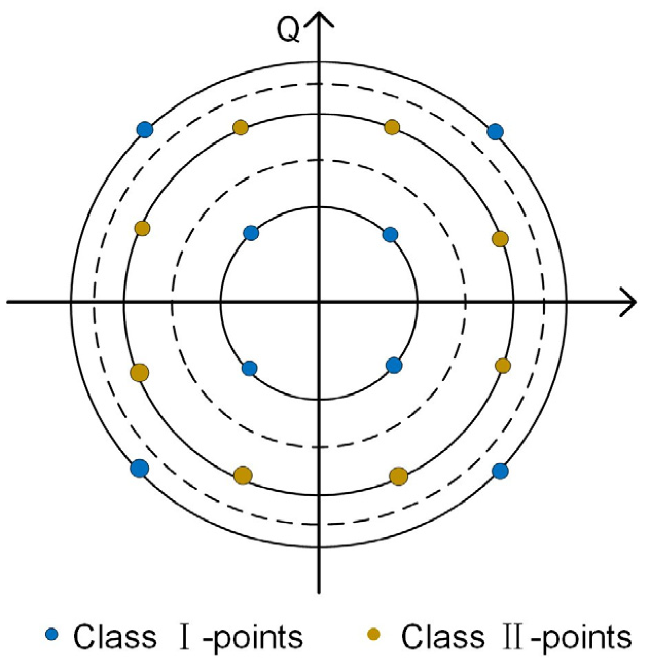
2.2. Viterbi–Viterbi Algorithm

For the 16QAM signal, the principle of Viterbi–Viterbi (VV) algorithms is to divide the all-constellation points into three groups [40]. As shown in Figure 2, the points on the inner circle and outer circle belong to class I, and the points on the middle circle belong to class II. Assume that the total phase of the received signal is:
θ k = θ S ( k ) + Δ w k T i + θ n + θ A S E
where θ S denotes the information phase, Δ w k T i denotes the phase caused by frequency offset and has been removed by the previous frequency offset estimation, θ n denotes the phase caused by laser linewidth and θ A S E denotes the noise phase [40]. Then, the rest phase can be calculated and wiped off through the fourth power method. So, raise the rest by the fourth power method:
V 4 ( k ) = e x p { j 4 θ S ( k ) } · e x p { j 4 θ n } · e x p { j 4 θ A S E }
Assume θ s = { 0 , π 2 , π , π 2 } , we can remove the modulation phase of the points belong to class I by taking the fourth power of the received QAM signals after judging the obtained constellation points according to the threshold of three circles. Then, the noise phase can be removed by adding and averaging V 4 ( k ) and the phase offset estimation phase:
θ e = 1 4 · a r g [ 1 N V 4 ( i ) ]
can be obtained after extracting the angle. Finally, the values of the polarization states, which are multiplied by e j θ e , can compensate the phase after the previous frequency offset estimation. Furthermore, to obtain more accurate and reliable phase noise estimation, the output signal is input into the maximum likelihood (ML) estimator.

2.3. Improved New Algorithm Based on VV (NVV)
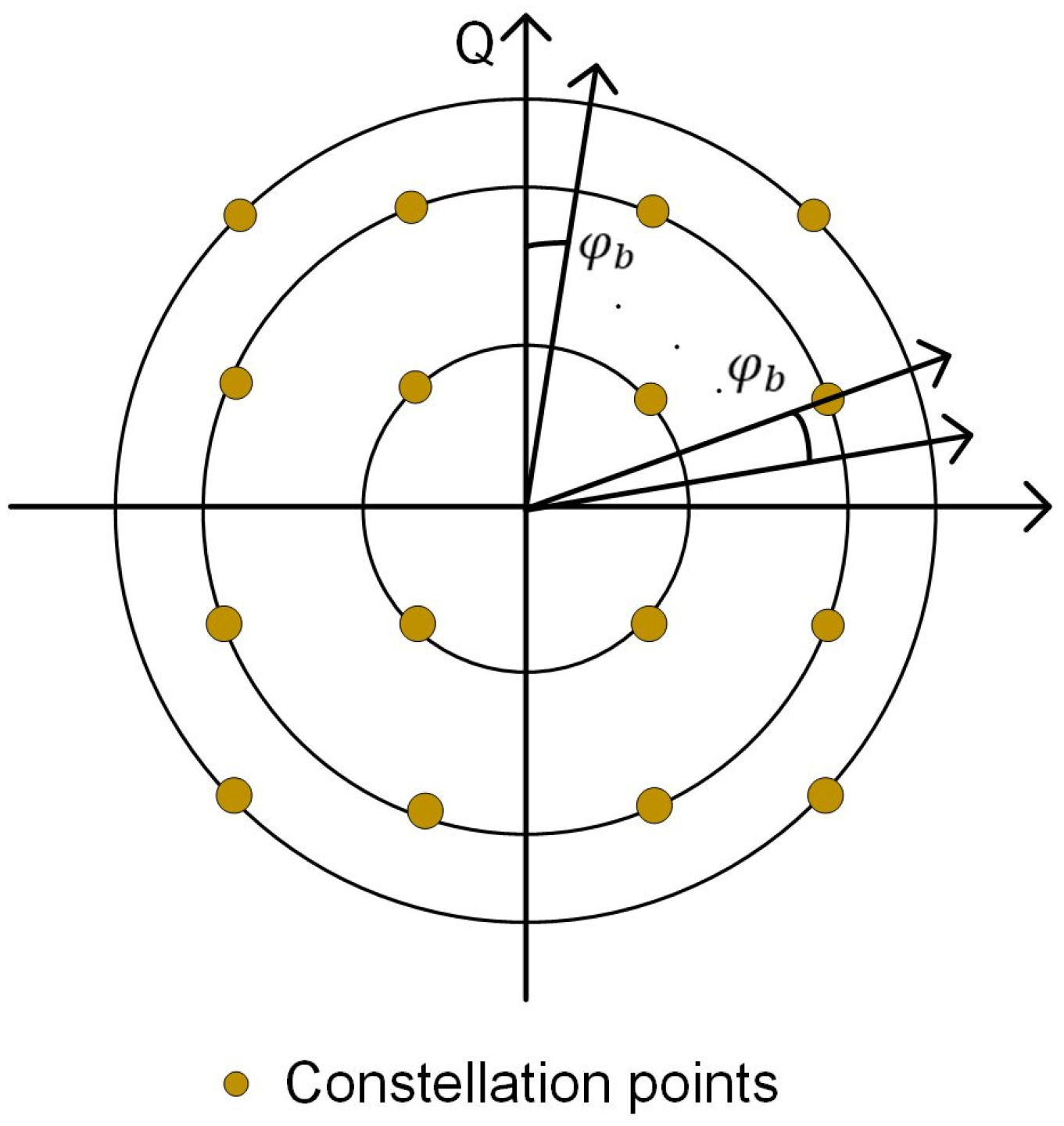
The conventional VV algorithm estimates the constant phase offset out of the White Gaussian Noise by averaging over a window with several symbols (assuming a constant phase offset within the window) [41]. However, due to the strong laser phase noise for optical transmission, the phase error can change dynamically from symbol to symbol. First, we can obtain the complex samples of the received complex envelope
A k * = I k * + j Q k * = C · ( I k + j Q k ) · e ( j Δ ϕ k ) + n k t o t = a k * · e ( j ϕ k * )
at the center of the symbols after sampling of the received in-phase and quadrature photocurrents I * ( t ) and Q * ( t ) . In (6), C is a constant and n k t o t represents the complex shot noise. The total phase error can be determined from the information provided by each symbol sample.
Δ φ k t o t = φ k * φ k
where φ k * is the received phase and φ k is the instant modulation angle. For example, for Square-16-QAM modulation, twelve different phase angles are possible, and the phase distances are not equal. Thus, the QAM constellation points are partitioned into two groups. We have the possibility to wipe the modulation for the Class I-points by selecting these points through amplitude decisions at thresholds in between the three amplitude levels and then take the fourth power of the received QAM-signal
( A k * ) 4 = ( a k * ) 4 · e ( j 4 φ k * )
The phase can only be determined modulo 2π Mod is a kind of modular operation and its function is to limit the angle between 0° and 360° (or 0–2π).
a r g { ( A k * ) 4 } = ( 4 · φ k * ) m o d ( 2 π ) = π + ( 4 · Δ φ k t o t ) m o d ( 2 π )
The total phase error can be calculated with an uncertainty of n · π / 2 .
Δ φ k t o t = a r g ( A k * ) 4 π 4 ± n · π 2 , n { 0 , 1 , 2 , , }   for   class / - points
The correction with the total phase error rotates the phase exactly to the instant modulation angle φ k for class II points. Then, we can obtain a Class II correction angle through the last Class I correction angle. The biggest advantage of this improved algorithm is that it can improve the performance of the system and reduce the time complexity.

2.4. BPS Algorithm

The BPS algorithm is adaptable to all modulation formats [40]. As shown in Figure 3, the received optical signal is rotated through the B test phase places in the constellation plane, respectively, where B is the number of test phases, and the test phase is:
φ b = π 2 × b B , b { 0 , 1 , 2 , , B 1 }
The value that might have been in the interval of [0,2π] was calculated on [ 0 , π / 2 ] due to the phase ambiguity of π / 2 . These test phases φ b are all possible noise values of the received signal. The value of B will also directly influence the accuracy of the algorithm, and the estimated value of phase noise will be more accurate when the value of B is larger. However, accurate estimation will bring the disadvantage of increasing computational complexity. Therefore, the main idea of the BPS algorithm is to assume the test phase as far as possible in advance, then multiply the received optical signal and the test phase to send to the decision module for judgement, and then calculate the minimum modulus:
m i n { | d ( k , b ) | 2 } = m i n { | y k e x p ( j φ b ) [ y k e x p ( j φ b ) ] D | 2 }
to estimate the phase noise value, a two-stage BPS/ML algorithm has also been proposed in the other literature. In the first stage, the BPS algorithm is still used for rough estimation to obtain a rough position of the best phase angle of the constellation point. Because the precision of the first rough estimation is low, the number of test phases p can be reduced to improve the problem of high computational complexity. Therefore, an ML phase estimator can be introduced in the second stage to improve the accuracy of the first-stage estimation. In short, the BPS algorithm has the advantage of effectively compensating the phase noise of the 16QAM signal and adapting to the higher-order QAM modulation format, but it will increase the computational complexity.

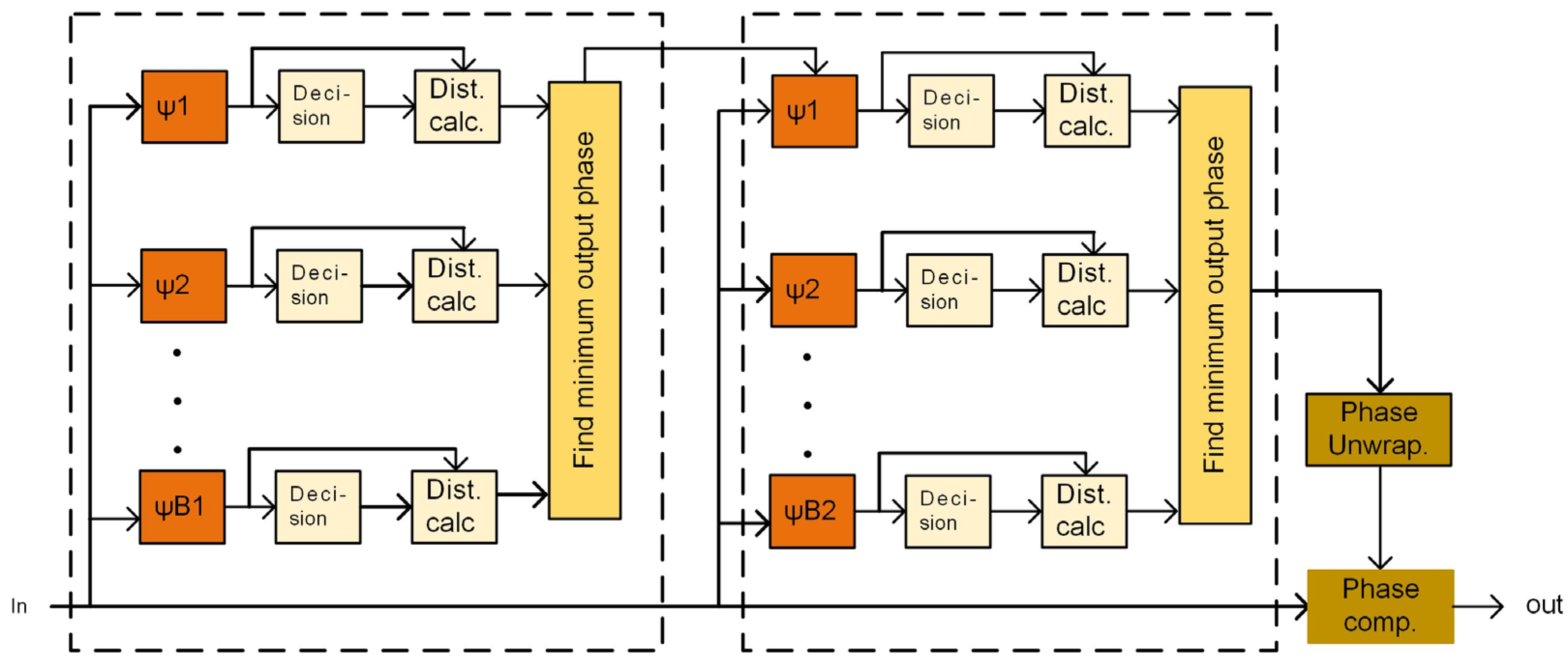
2.5. 2S-BPS Algorithm
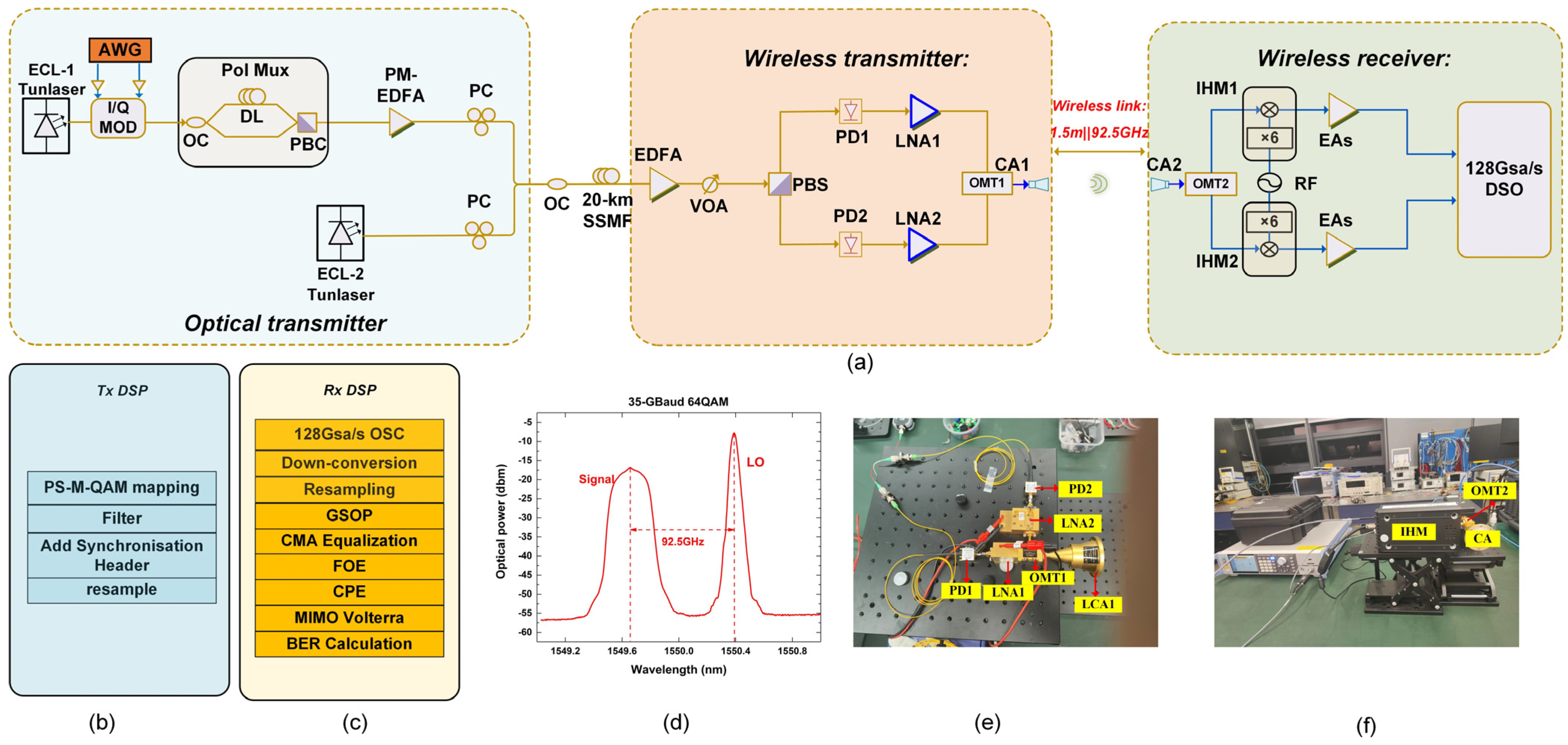
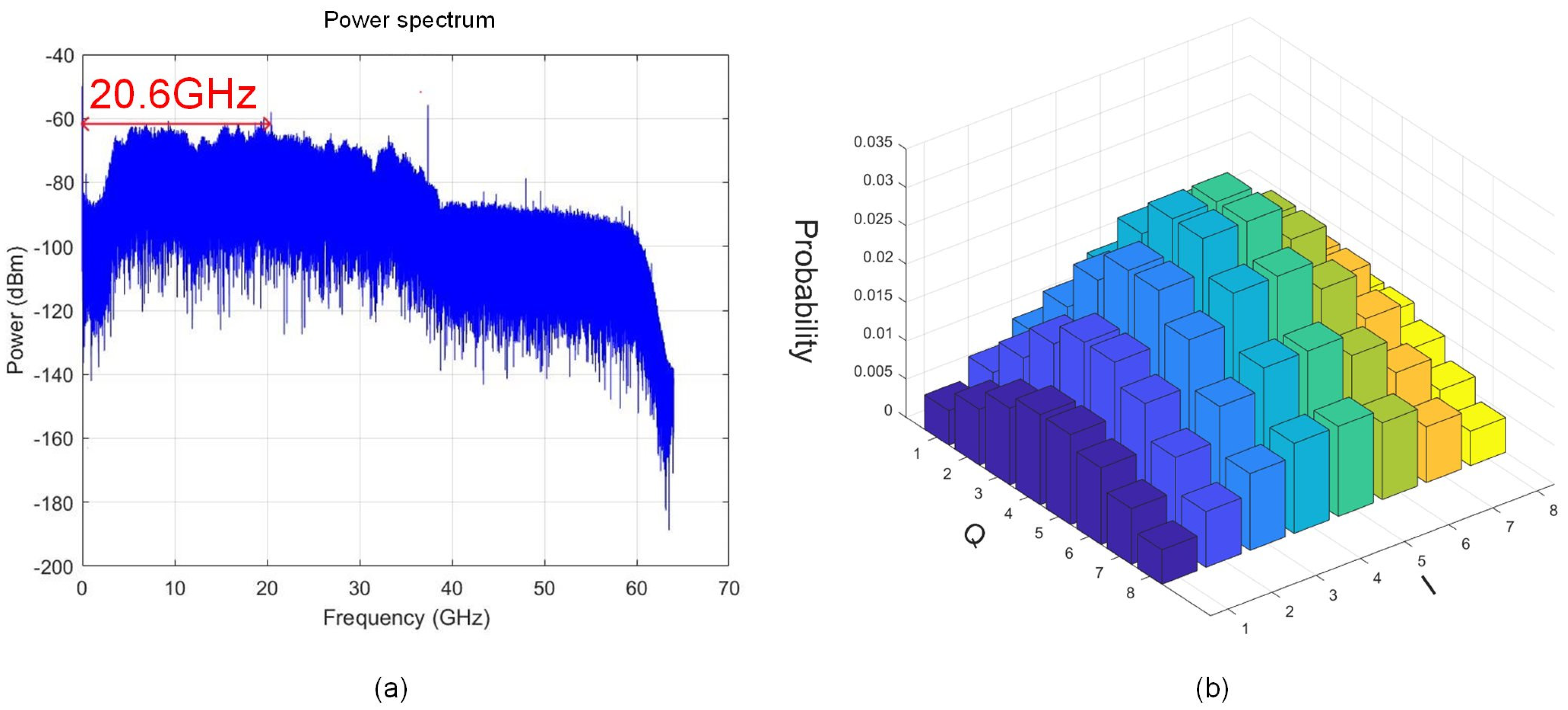
BPS is a feed-forward algorithm that tests different phases to compensate for phase distortions. Breaking the BPS algorithm into two stages with B1 and B2 test phases in the first and the second stages is a common implementation for complexity reduction [35]. The phase division of the second stage is a redivision of the first stage. The 2S-BPS algorithm tests up to B1(B2 + 1) different phase values while the complexity is proportional to BT = B1 + B2. Comparing the BPS algorithm, the complexity of the 2S-BPS algorithm will reduce greatly. Figure 4 shows the block diagram of the 2S-BPS diagram.

3. Experiment Setup

At the optical transmitter module, as shown in Figure 5a, we employ the two free-running tunable external cavity lasers (ECL-1 and ECL-2) with 100 kHz linewidth. ECL1 operates at 1549.316 nm with 14 dBm output power, and ECL2 with an output power of 8 dBm has a frequency offset of 92.5 GHz from the ECL1. A 92 Gb/s arbitrary waveform generator (AWG, M8196A) with a 3 dB analog bandwidth of 32 GHz and 8-bit resolution produces the in-phase and quadrature components of 16QAM and 64QAM signals. Next, the output optical signals from the I/Q modulator after passing through the polarization multiplexer module are amplified by a polarization-maintaining erbium-doped fiber amplifier (PM-EDFA) to compensate for the insertion loss of the modulator. In the polarization multiplexer module, the polarization-maintaining optical coupler (OC) is utilized to split the signal into two branches. One arm contains an optical delay line (DL) to provide a symbol delay. Finally, a polarization beam combiner (PBC) is used to recombine the signals. Polarization controllers (PCs) are required to adjust the incident direction to maximize output power. The optical signal and ECL-2 are combined using an OC, and then the coupled signal is transmitted over 20 km standard single-mode fiber (SSMF).
At the wireless transmitter module, another EDFA is used to adjust the power and the optical signal is then adjusted by a variable optical Attenuator. The X- and Y- polarization diversities are achieved through a polarization beam splitter (PBS) and then enter the photodetectors (PDs) with a responsivity of 0.6 A/W and 3 dB bandwidth of 100 GHz to generate W-band mm-wave signals. Then, the signals from the PDs are amplified by LNA1 and LNA2 with 35 dB gain, respectively, to maximize the mm-wave wireless air interface rate (WAIR). The above two W-band components (LNA1 and LNA2) are transparently transmitted by a dual-polarized single-input single-output (SISO) wireless link. To separate the dual orthogonally polarized channels at the W-band, we use a pair of orthomode transducers (OMT1 and OMT2) with 35 dB isolation between two orthogonal polarization directions as H/V diplexers for communication links. Subsequently, the signals are transmitted to wireless space and received by a pair of conical horn antennas (CA1 and CA2) with a total gain of 2 × 30 dBi. We use a pair of OMTs and a pair of CA to achieve the transparent transmission of a dual-polarized SISO wireless link. The stability and robustness of optical wireless integrated systems can be significantly improved obviously because the SISO link structure simplifies the traditional complicated 2 × 2 MIMO wireless links.
At the wireless receiver module, the mm-wave output signals from OMT2 are down-converted to an intermediate-frequency (IF) by two mixers actuated by an RF carrier source. By setting the input RF source to 18.85 GHz, we can obtain two IF signals with the central frequency of 20.6 GHz (18.85 × 6 − 92.5 = 20.6 GHz). Then, the obtained intermediate-frequency (IF) signal at 20.6 GHz is enhanced by electrical amplifiers (EAs) and captured by a digital storage oscilloscope (DSO) with an operating sample rate of 128 GSa/s and 3 dB bandwidth of 59 GHz for decoding. The main DSP module at the transmitting end and the receiving end of the experimental setup are shown in Figure 5b,c. In the receiving end, the received signal is processed by resampling, Gram-Schmidt orthogonalization process (GSOP). CMA equalization algorithm can effectively suppress system noise and crosstalk and has the function of polarization demultiplexing. In the frequency offset estimation (FOE) step, the residual frequency offset of the received signal resulting from frequency drifts of the lasers is removed. Moreover, we use and compare four kinds of algorithms in the CPR module to carry on phase recovery, respectively. The linear intra- and inter-crosstalk between the two polarization directions have been overcome by the prior CMA filter in our fiber-wireless hybrid channels. However, nonlinear crosstalk still remains, which may degrade the system performance to a great extent. So, we also employ a second-order MIMO Volterra nonlinear equalizer (VNE) due to compromise to estimate the nonlinear impairment. The X- and Y-polarization signals can be jointly equalized through MIMO VNE, and the technology can not only keep the two BER balanced but also improve performance when using MIMO VNE. Additionally, a 57-tap direct-detection least mean square (DD-LMS) equalizer is employed to compensate for the remaining linear damage. Figure 5d shows the optical spectrum after optical polarization diversity. The signal and the local oscillator (LO) have 92.5 GHz frequency spacing and a 10-dB power difference. Figure 5e,f shows the experimental setup and the picture of different experimental devices.

4. Experiment Results

In this section, we analyze the experiment result through the BER performance of 23-Gbaud and 35-Gbaud for 16QAM, PS-16QAM, 64QAM and PS-64QAM signal and the computational complexity of the four kinds of CPR algorithms (VV algorithm, NVV algorithm, BPS algorithm and 2S-BPS algorithm).

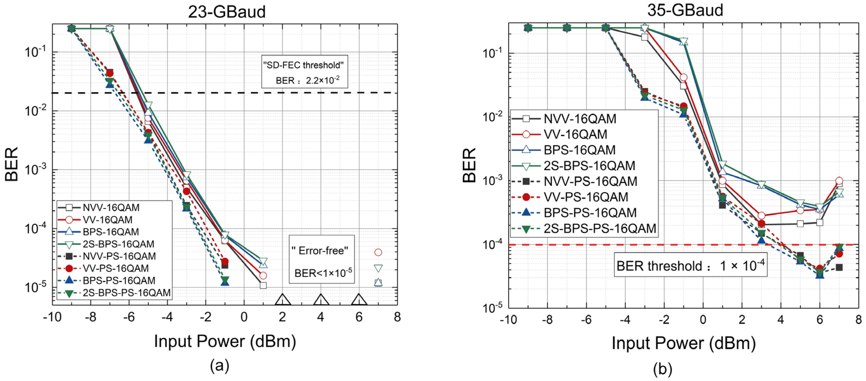
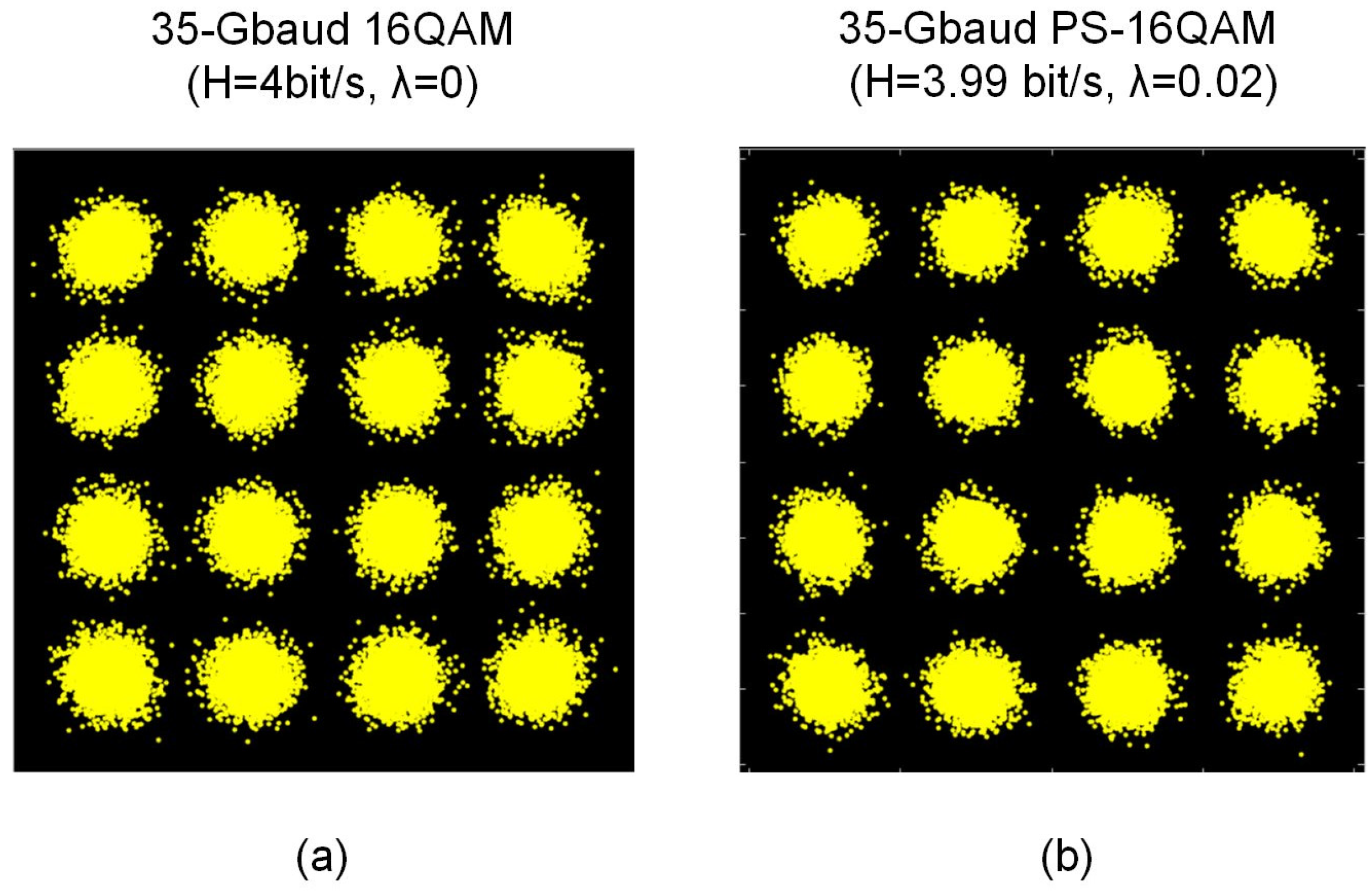
4.1. The Experiment Result of 16QAM and PS-16QAM

Figure 6a,b illustrate the BER performance of 23-Gbaud and 35-Gbaud for 16QAM and PS-16QAM signals versus the input power of PDs. As shown in Figure 7a,b, shows the electrical spectrum of the obtained 20.6 GHz IF signal after analog down conversion and illustrates the probabilistic shaping diagram of PS-16QAM when λ (shaping factor) is 0.02. Figure 8a,b show the constellation diagrams of 35-Gbaud 16QAM and PS-16QAM.
The experiment results in Figure 6 depict the BER performance of PS-16QAM is better than that of 16QAM for all input power points. Especially for the 35-Gbaud 16QAM signal, the BER performance of the 16QAM signal combined with PS technology can achieve below 10−4. Note that the behavior of the BER curves is non-monotonic because of the existence of saturation phenomenon. Initially, the BER performance of the system improves as the input power for all situations when the power is in the noise-limited case. However, BER performance starts to degrade when the input power is higher than 3 dBm for the non-linear case for the 23-Gbaud 16QAM signal. The best BER performance can even reach the situation of error-free (<1 × 10⁻⁵) when the input power is around 3 dBm using the four kinds of algorithms. Furthermore, the BER performance of the BPS algorithm is the worst among the four kinds of algorithms for 23-Gbaud 16QAM. The improved VV algorithm’s BER performance is the best and a little better than the other algorithms. Nevertheless, for the PS-16QAM signal, the BER performance of the BPS algorithm is better than the other algorithms because the BPS algorithm tests more phase angles and has higher estimation accuracy than the other algorithms. The two types of VV algorithms’ BER performance are similar, but the time complexity of the improved VV algorithm is lower than another algorithm. The time complexity of the BPS algorithm for 16QAM and PS-16QAM is the worst because the algorithm will divide as many test phases as possible in an interval to estimate the phase. So, we use a two-stage approach called 2S-BPS algorithm to reduce the time complexity of the BPS algorithm, but the BER performance of 2S-BPS algorithm is a little bit worse than that of the BPS algorithm. As shown in Figure 6b, the trend of the BER curves of four algorithms for the 35-Gbaud 16QAM signal is similar to that for the 23-Gbaud signal. The BER performance of the 23-Gbaud signal is significantly about two magnitudes better than that of 35-Gbaud signal for 16QAM and PS-16QAM. As shown in Figure 8, the constellation diagram of 16QAM has little difference from the constellation diagram of PS-16QAM when λ is 0.02. Especially when the input power is around 3 dBm for the PS-16QAM signal, we can achieve error-free wireless transmission over the fusion link of 20 km fiber-optic and 1.5 m RF wireless distance with a BER below the FEC threshold of 1 × 10⁻⁴ assuming SD-FEC.

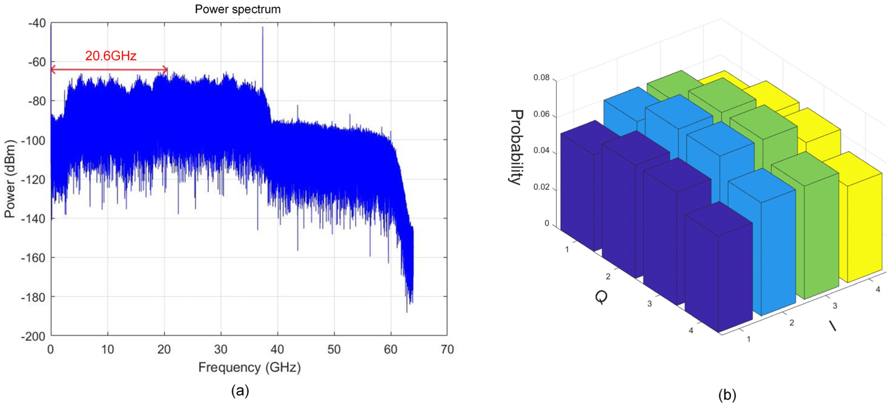
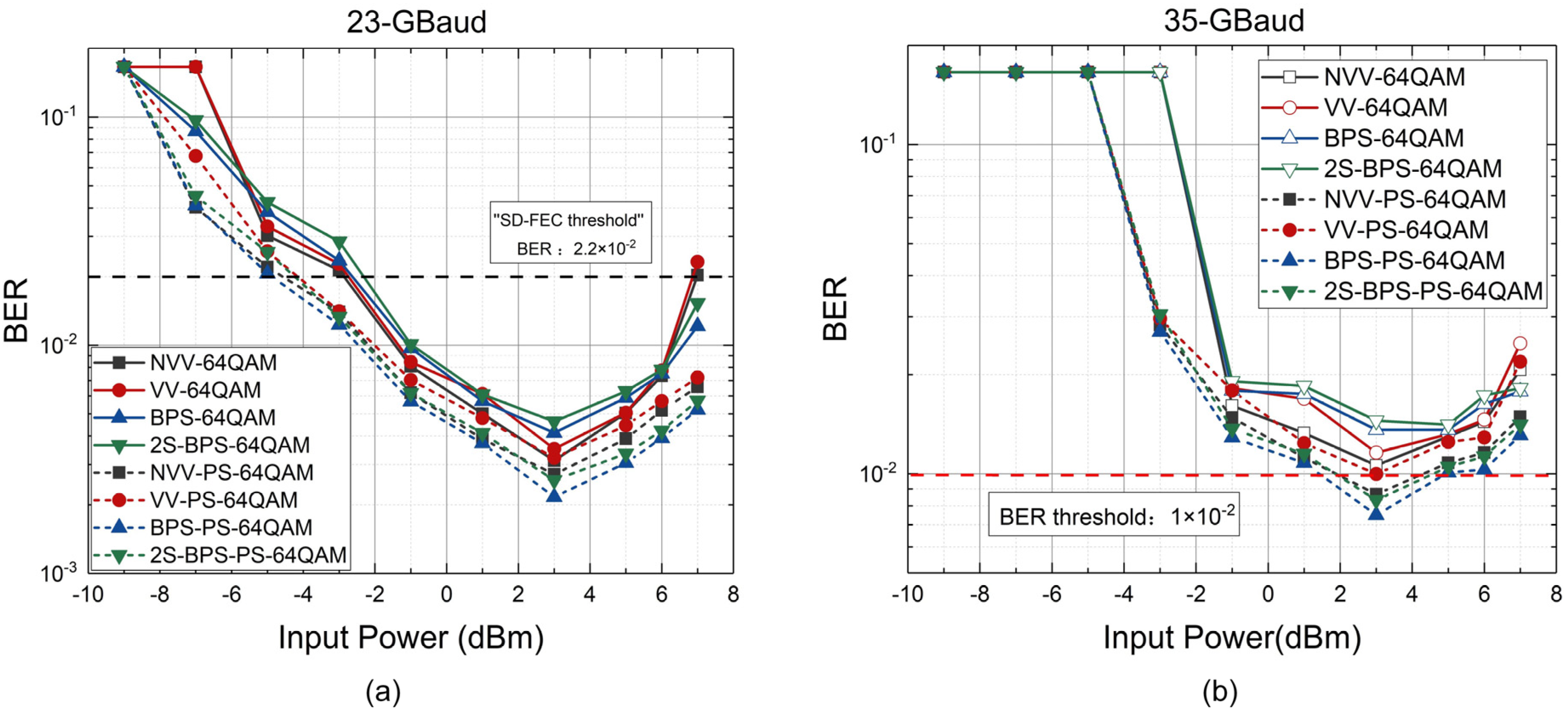
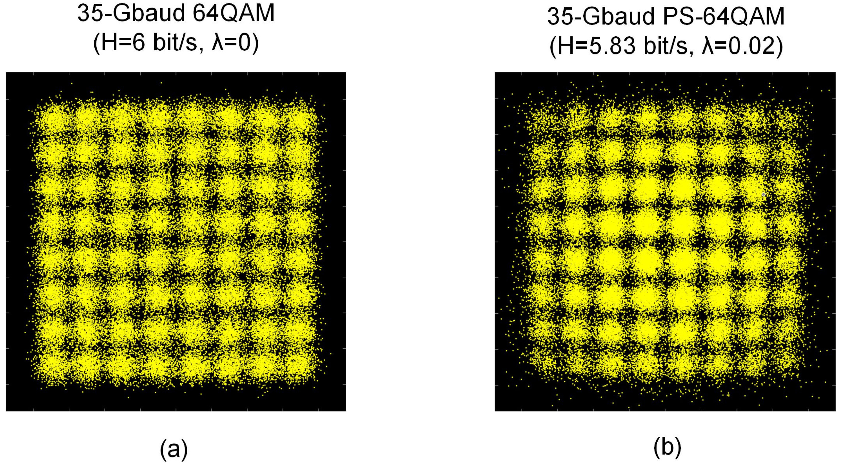
4.2. The Experiment Result of 64QAM and PS-64QAM

Then, we also demonstrate and compare the BER performance of 23-Gbaud and 35-Gbaud for 64QAM and PS-64QAM signals in Figure 9a,b. Figure 10a shows the electrical spectrum of the obtained 20.6 GHz IF signal after analog down conversion. Figure 10b illustrates that the probabilistic shaping diagram of PS-64QAM when λ (shaping factor) is 0.02. The constellation diagrams of 35-Gbaud 64QAM and PS-64QAM are shown in Figure 11a,b.
The high-order QAM format can significantly enhance spectral efficiency and generate high-rate data to improve the system throughput compared with the simple and low-order modulation scheme. However, high-order modulation increases the demand for SNR, resulting in poorer BER performance for 64QAM signals compared with 16QAM signals. For example, the BER performance of the 35-Gbaud signal for 16QAM is about two magnitudes better than that of the 35-Gbaud signal for 64QAM. Furthermore, the trend of BER for 64QAM and PS-64QAM is similar to 16QAM and PS-16QAM, and the minimum BER value of the input power is also around 3 dBm. Similarly, the performance of BER will initially improve with the increase in input optical power for the four CPR algorithms. However, the performance will also decline gradually due to the fact that the input optical power is saturated when the optical power is higher than 3 dBm. We can further increase the throughput and spectral efficiency of the communication system when the combination of the PS technology and high-order QAM format is employed. We can easily find that the high-amplitude symbols of the constellation diagrams for PS-64QAM are reduced compared to 64QAM. The decrease in the probability of the high-amplitude λ symbols makes the PS-QAM signals less susceptible to the nonlinearity introduced by LNAs and PDs. Especially when λ is bigger, the probability of the high-amplitude symbol is smaller, and the receiving end signal is harder to recover. Furthermore, the performance of the 23-Gbaud PS-64QAM signal is about one magnitude better than that of the 35-Gbaud PS-64QAM signal. Especially for the 35-Gbaud 64QAM signal, the BER performance of the 64QAM signal combined with PS technology can achieve below 10−2 for four algorithms. In consideration of the overhead of the SD-FEC, the total maximum net data of the system is 2 × 35 × [5.83 – 6 × (1 − 0.8)] = 324.1 Gbps.

4.3. Computational Complexity Analysis

Finally, the computational complexities of the four above-mentioned CPR algorithms are investigated. Based on the result given in [42,43], we can easily compare the complexities of the four kinds of CPR algorithms through the real additions (or subtractions), the real multiplications (or divisions) and computation of root squares. The number of each type of operation is shown in Table 2, where N1 represents the length of symbol sequence per block of the BPS algorithm, BM indicates the total number of test phases of the BPS algorithm, B1 and B2 (BT = B1 + B2) indicate the number of test phases for the first and second stages of 2S-BPS algorithm, N2 (about 10N1) represents the length of symbol sequence per block of the other two algorithms. Through using a two-stage method, the complexity of the BPS algorithm will greatly reduce while the performance of the 2S-BPS algorithm has little change. Furthermore, the improved new algorithm based on VV also has lower performance than the VV algorithm. Because the algorithm principle is different, the complexity of the algorithm based on the VV principle is much lower than that based on the BPS principle. From Table 1, we can obviously see that the computational complexity of the BPS algorithm is the biggest, and the computational complexity of the improved VV algorithm is the smallest.

5. Discussion

In conclusion, by using a photonics-aided scheme, the different signals at different baud rates using different carrier phase recovery (CPR) algorithms are transmitted at W-band over the fusion link of 20 km fiber-optic and 1.5 m RF wireless distance at 92.5 GHz. Compared with the other three algorithms, the BPS algorithm is more suitable for PS-QAM signal because of testing more phase angles, but it will have higher computational complexity than other algorithms. However, PS impact on BPS can also affect the overall system performance, especially under the conditions of a low signal-to-noise ratio. Therefore, algorithms with better performance and more suitable for PS technology will be further researched in future work.

Author Contributions

Conceptualization, J.Z. (Junhao Zhang) and J.Z. (Jiao Zhang); methodology, J.Z. (Junhao Zhang) and J.Z. (Jiao Zhang); software, Q.W., S.X. and Y.C.; validation, B.H., M.L. and Y.C.; formal analysis, J.Z. (Junhao Zhang), J.C., W.L. and J.Z. (Jiao Zhang); investigation, J.Z. (Junhao Zhang) and J.Z. (Jiao Zhang); resources, J.Z. (Junhao Zhang); data curation, J.Z. (Junhao Zhang); writing, original draft preparation, J.Z. (Junhao Zhang); writing, review and editing, J.Z. (Junhao Zhang), Y.Z., L.T., X.C. and J.Z. (Jiao Zhang); supervision, M.Z.; project administration, M.Z. All authors have read and agreed to the published version of the manuscript.

Funding

This research was supported in part by the National Key Research and Development Program of China (2022YFB2903800), the National Natural Science Foundation of China (62101121, 62101126, 62201397, 62201393, 62271135), the project funded by China Postdoctoral Science Foundation (2021M702501 and 2022T150486), the Key Research and Development Program of Jiangsu Province (BE2020012).

Institutional Review Board Statement

Not applicable.

Informed Consent Statement

Not applicable.

Data Availability Statement

Data underlying the results presented in this paper are not publicly available at this time but may be obtained from the authors upon reasonable request.

Conflicts of Interest

The authors declare no conflict of interest.

References

  1. Li, W.; Yu, J.; Wang, F.; Ji, X.; Yang, X.; Zheng, T.; Wang, Q.; Zhou, W.; Yu, J.; Zhao, F. Photonics millimeter wave bidirectional full-duplex communication based on polarization multiplexing. Opt. Lett. 2022, 47, 6389–6392. [Google Scholar] [CrossRef] [PubMed]
  2. Zhu, M.; Zhang, J.; Hua, B.C. Ultra-wideband fiber-THz-fiber seamless integration communication system toward 6G: Architecture, key techniques, and testbed implementation. Sci. China Inf. Sci. 2023, 66, 113301. [Google Scholar] [CrossRef]
  3. Lu, H.; Wu, H.; Li, C.; Ho, C.; Yang, Z.; Cheng, M.; Lu, C. Bidirectional fiber-IVLLC and fiber-wireless convergence system with two orthogonally polarized optical sidebands. Opt. Express 2017, 25, 9743–9754. [Google Scholar] [CrossRef]
  4. Li, X.; Yu, J.; Zhao, L.; Wang, K.; Wang, C.; Zhao, M.; Zhou, W.; Xiao, J. 1-Tb/s Millimeter-Wave Signal Wireless Delivery at D-Band. J. Light. Technol. 2019, 37, 196–204. [Google Scholar] [CrossRef]
  5. Jia, S.; Zhang, L.; Wang, S.; Li, W.; Qiao, M.; Lu, Z.; Idrees, N.M.; Pang, X.; Hu, H.; Zhang, X.; et al. 2 × 300 Gbit/s line rate PS-64QAM-OFDM THz photonic-wireless transmission. J. Light. Technol. 2020, 38, 4715–4721. [Google Scholar] [CrossRef]
  6. Zhang, J.; Zhu, M.; Lei, M.; Hua, B.; Cai, Y.; Zou, Y.; Tian, L.; Li, A.; Huang, Y.; Yu, J.; et al. Demonstration of Real-time 125.516 Gbit/s Transparent Fiber-THz-Fiber Link Transmission at 360~430 GHz based on Photonic Down-Conversion. In Proceedings of the 2022 Optical Fiber Communication Conference (OFC), San Diego, CA, USA, 6–10 March 2022. [Google Scholar]
  7. Zhang, J.; Zhu, M.; Lei, M.; Hua, B.; Cai, Y.; Zou, Y.; Tian, L.; Li, A.; Wang, Y.; Huang, Y.; et al. Real-time demonstration of 103.125-Gbps fiber–THz–fiber 2 × 2 MIMO transparent transmission at 360–430 GHz based on photonics. Opt. Lett. 2022, 47, 1214–1217. [Google Scholar] [CrossRef]
  8. Li, X.; Yu, J.; Chang, G. Photonics-Aided Millimeter-Wave Technologies for Extreme Mobile Broadband Communications in 5G. J. Light. Technol. 2020, 38, 366–378. [Google Scholar] [CrossRef]
  9. Rommel, S.; Dodane, D.; Grivas, E.; Cimoli, B.; Bourderionnet, J.; Feugnet, G.; Morales, A.; Pikasis, E.; Roeloffzen, C.; van Dijk, P.; et al. Towards a Scaleable 5G Fronthaul: Analog Radio-over-Fiber and Space Division Multiplexing. J. Light. Technol. 2020, 38, 5412–5422. [Google Scholar] [CrossRef]
  10. Li, X.; Yu, J.; Dong, Z.; Zhang, J.; Chi, N.; Yu, J. Investigation of interference in multiple-input multiple-output wireless transmission at W band for an optical wireless integration system. Opt. Lett. 2013, 38, 742–744. [Google Scholar] [CrossRef]
  11. Li, W.; Tan, Y.; Zhu, B.; Wang, F.; Wang, Y.; Ding, J.; Wang, K.; Zhao, L.; Zhou, W.; Yu, J.; et al. 127.8 Gb/s OFDM-PDM-PS256QAM W-Band Signal Delivery over 10 km SMF-28 and 4.6 km Wireless Distance. In Proceedings of the European Conference on Optical Communication (ECOC), Basel, Switzerland, 18–22 September 2022. [Google Scholar]
  12. Yu, J.; Li, X.; Zhang, J.; Xiao, J. 432-Gb/s PDM-16QAM signal wireless delivery at W-band using optical and antenna polarization multiplexing. In Proceedings of the European Conference on Optical Communication (ECOC), Cannes, France, 21–25 September 2014. [Google Scholar]
  13. Dat, P.T.; Rottenberg, F.; Kanno, A.; Inagaki, K.; Louveaux, J.; Yamamoto, N.; Kawanishi, T. 132 Gb/s 3 × 3 Full MIMO Fiber-Wireless Seamless System in W Band Using WDM/PDM RoF Transmission. In Proceedings of the European Conference on Optical Communications (ECOC), Brussels, Belgium, 6–10 December 2020. [Google Scholar]
  14. Puerta, R.; Yu, J.; Li, X.; Xu, Y.; Olmos, J.J.V.; Monroy, I.T. Single-Carrier Dual-Polarization 328-Gb/s Wireless Transmission in a D-Band Millimeter Wave 2 × 2 MU-MIMO Radio-Over-Fiber System. J. Light. Technol. 2018, 36, 587–593. [Google Scholar] [CrossRef]
  15. Kawanishi, T. THz and photonic seamless communications. J. Light. Technol. 2019, 37, 1671–1679. [Google Scholar] [CrossRef]
  16. Huang, P.; Xie, Z.; Hsieh, T.; Yu, S.; Wei, C.; Chi, S.; Lin, C. 3 × 3 MIMO 60-GHz Direct-Detection OFDM RoFMF System with Mitigation of Optical Carrier Power Fading. In Proceedings of the Optical Fiber Communication Conference (OFC), San Francisco, CA, USA, 6–10 June 2021. [Google Scholar]
  17. Wang, X.; Zhang, Q.; Yu, J.; Xin, X.; Lu, K.; Gao, R.; Ren, J.; Tian, F.; Tian, Q.; Wang, C.; et al. Carrier phase recovery friendly probabilistic shaping scheme based on a quasi-Maxwell–Boltzmann distribution model. Opt. Lett. 2020, 45, 4883–4886. [Google Scholar] [CrossRef]
  18. Mello, D.A.A.; Barbosa, F.A.; Reis, J.D. Interplay of Probabilistic Shaping and the Blind Phase Search Algorithm. J. Light. Technol. 2018, 36, 5096–5105. [Google Scholar] [CrossRef] [Green Version]
  19. Wu, K.; He, J.; Zhou, Z.; He, J.; Shi, J. Probabilistic Amplitude Shaping for a 64-QAM OFDM W-Band RoF System. IEEE Photonics Technol. Lett. 2019, 31, 1076–1079. [Google Scholar] [CrossRef]
  20. Shao, Y.; Hong, Y.; Hu, Z.; Chen, L.K. Capacity maximization of owc systems via joint precoding and probabilistic shaping. IEEE Photonics Technol. Lett. 2019, 31, 1013–1016. [Google Scholar] [CrossRef]
  21. Wiegart, T.; Ros, F.D.; Yankov, M.P.; Steiner, F.; Gaiarin, S.; Wesel, R.D. Probabilistically shaped 4-pam for short-reach im/dd links with a peak power constraint. J. Light. Technol. 2021, 39, 400–405. [Google Scholar] [CrossRef]
  22. Barbosa, F.A.; Mello, D.A.A. Shaping Factor Detuning for Optimized Phase Recovery in Probabilistically-Shaped Systems. In Proceedings of the Optical Fiber Communication Conference (OFC), San Diego, CA, USA, 3–7 March 2019; OSA Technical Digest. Optica Publishing Group: San Diego, USA, 2019. [Google Scholar]
  23. Di Rosa, G.; Richte, A. Likelihood-Based Selection Radius Directed Equalizer with Time-Multiplexed Pilot Symbols for Probabilistically Shaped QAM. J. Light. Technol. 2021, 39, 6107–6119. [Google Scholar]
  24. Yan, Q.; Liu, L.; Hong, X. Blind Carrier Frequency Offset Estimation in Coherent Optical Communication Systems with Probabilistically Shaped M-QAM. J. Light. Technol. 2019, 37, 5856–5866. [Google Scholar] [CrossRef]
  25. Dris, S.; Alreesh, S.; Richter, A. Blind Polarization Demultiplexing and Equalization of Probabilistically Shaped QAM. In Proceedings of the Optical Fiber Communication Conference (OFC), San Diego, CA, USA, 3–7 March 2019. [Google Scholar]
  26. Liu, W.; Yang, T.; Chen, X.; You, J. Low-Complexity Frequency Offset Estimation for Probabilistically Shaped MQAM Coherent Optical Systems. IEEE Photonics J. 2022, 14, 3189993. [Google Scholar] [CrossRef]
  27. Lauinger, V.; Buchali, F.; Schmalen, L. Improving the Bootstrap of Blind Equalizers with Variational Autoencoders. In Proceedings of the Optical Fiber Communication Conference (OFC), San Diego, CA, USA, 5–9 March 2023; Technical Digest Series. Optica Publishing Group: Washington, DC, USA, 2023. [Google Scholar]
  28. Civelli, S.; Parente, E.; Forestieri, E.; Secondini, M. On the Nonlinear Shaping Gain With Probabilistic Shaping and Carrier Phase Recovery. J. Light. Technol. 2023, 41, 3046–3056. [Google Scholar] [CrossRef]
  29. He, Z.; Du, J.; Chen, X.; Shen, W.; Huang, Y.; Wang, C.; Xu, K.; He, Z. Machine learning aided inverse design for few-mode fiber weak-coupling optimization. Opt. Express 2020, 28, 21668–21681. [Google Scholar] [CrossRef]
  30. Tang, X.; Xu, H.; Bai, C.; Fan, Y.; Zhang, Y.; Yang, L.; Cao, L.; Sun, W.; Cui, N. Blind frequency offset estimation using the optimal decision threshold-assisted QPSK-partition method for probabilistically shaped MQAM system. Opt. Express 2022, 30, 37175–37192. [Google Scholar]
  31. Cao, F.; Gao, M.; Wang, P.; You, X.; Shen, G. Optimized blind equalization for probabilistically shaped high-order QAM signals. Chin. Opt. Lett. 2022, 20, 080601. [Google Scholar] [CrossRef]
  32. Zhang, Q.; Shu, C. Viterbi and Viterbi Algorithm based Phase Recovery for Probabilistically Shaped Signals. J. Light. Technol. 2021, 39, 1364–1370. [Google Scholar] [CrossRef]
  33. Nguyen, T.; Zhang, T.; Giacoumidis, E.; Ali, A.A.; Tan, M.; Harper, P.; Barry, L.; Ellis, A. Coupled Transceiver-Fiber Nonlinearity Compensation Based on Machine Learning for Probabilistic Shaping System. J. Light. Technol. 2021, 39, 388–399. [Google Scholar]
  34. Steiner, F.; Ros, F.; Yankov, M.; Böcherer, G.; Schulte, P.; Forchhammer, S.; Kramer, G. Experimental Verification of Rate Flexibility and Probabilistic Shaping by 4D Signaling. In Proceedings of the Optical Fiber Communication Conference, San Diego, CA, USA, 5–9 March 2018; OSA Technical Digest (online). Optica Publishing Group: San Diego, CA, USA, 2018. [Google Scholar]
  35. Diniz, J.; Fan, Q.; Ranzini, S.; Khan, F.; Da Ros, F.; Zibar, D.; Lau, A. Low-complexity carrier phase recovery based on principal component analysis for square-QAM modulation formats. Optics. Express 2019, 27, 15617–15626. [Google Scholar]
  36. Zhang, N.; Zhang, X.; Cui, N.; Li, X.; Xi, L.; Zhang, W. A Kalman Filter Based Carrier Phase Recovery Scheme for Probabilistic Shaping M-QAM System. In Proceedings of the Opto-Electronics and Communications Conference, Taipei, Taiwan, 4–8 October 2020. [Google Scholar]
  37. Di Rosa, G.; Richter, A. Low Complexity Blind Carrier Phase Recovery for Probabilistically Shaped QAM. IEEE Photonics Technol. Lett. 2020, 32, 1109–1112. [Google Scholar] [CrossRef]
  38. Zhao, J.; Chen, L.K. Carrier Phase Recovery based on KL Divergence in Probabilistically Shaped Coherent Systems. J. Light. Technol. 2021, 39, 2684–2695. [Google Scholar] [CrossRef]
  39. Chen, Z.; Fu, S.; Tang, M.; Zhang, Z.; Qin, Y. Maximum probability directed blind phase search for PS-QAM with variable shaping factors. Opt. Express 2022, 30, 550–562. [Google Scholar] [CrossRef]
  40. Yu, J.; Chi, N. Digital Signal Processing in High-Speed Optical Fiber Communication; Beijing Tsinghua University Press: Beijing, China, 2018; Volume 57. [Google Scholar]
  41. Seimetz, M. Performance of Coherent Optical Square-16-QAM-Systems based on IQ-Transmitters and Homodyne Receivers with Digital Phase Estimation. In Proceedings of the Optical Fiber Communication Conference and Exposition and The National Fiber Optic Engineers Conference, Anaheim, CA, USA, 5–10 March 2006; Technical Digest (CD). Optica Publishing Group: San Diego, CA, USA, 2006. [Google Scholar]
  42. Wang, X.; Zhang, Q.; Xin, X.; Gao, R.; Lv, K.; Tian, Q.; Tian, F.; Wang, C.; Pan, X.; Wang, Y.; et al. Robust and Low-Complexity Principal Component-Based Phase Estimation Algorithm for Probabilistically Shaped Square-QAM Systems. J. Light. Technol. 2020, 38, 6153–6162. [Google Scholar] [CrossRef]
  43. Lagha, M.K.; Gerzaguet, R.; Bramerie, L.; Gay, M.; Chares, M.-L.; Peucheret, C.; Scalart, P. Blind Joint Polarization Demultiplexing and IQ Imbalance Compensation for 𝑀-QAM Coherent Optical Communications. J. Light. Technol. 2020, 38, 4213–4220. [Google Scholar] [CrossRef]
Figure 1. The diagram of optical fiber wireless application scenario.
Photonics 10 00927 g001
Figure 2. Partitioning of 16QAM constellation into two classes.
Photonics 10 00927 g002
Figure 3. The division of angles for constellation points for BPS algorithm.
Photonics 10 00927 g003
Figure 4. The block diagram of the 2S-BPS algorithm [35].
Photonics 10 00927 g004
Figure 5. (a) The experimental setup of photonics-aided W-band polarization multiplexing communication system; The block diagram of (b)Tx DSP; (c) Rx DSP; (d) The optical spectrum of 35-Gbaud 64QAM signal; (e,f) The photo of the experimental setup.
Photonics 10 00927 g005
Figure 6. BER performance curves of (a) 23-Gbaud; (b) 35-Gbaud 16QAM and PS-16QAM for four kinds of algorithms.
Photonics 10 00927 g006
Figure 7. (a) The electrical spectrum of 35-Gbaud 16QAM signal; (b)the probabilistic shaping diagram of PS-16QAM.
Photonics 10 00927 g007
Figure 8. The constellation diagrams of (a) 35-Gbaud 16QAM; (b) 35-Gbaud PS-16QAM.
Photonics 10 00927 g008
Figure 9. BER performance curves of (a) 23-Gbaud; (b) 35-Gbaud 64QAM and PS-64QAM for four kinds of algorithms.
Photonics 10 00927 g009
Figure 10. (a) The electrical spectrum of 35-GBaud 64QAM signal; (b) the probabilistic shaping diagram of PS-64QAM.
Photonics 10 00927 g010
Figure 11. The constellation diagrams of (a)35-Gbaud 64QAM; (b) 35-Gbaud PS-64QAM.
Photonics 10 00927 g011
Table 1. Summary of the latest CPR algorithms.
FormatFactorBaudAlgorithmYearReference
PS-64QAM0.250SPS2018[18]
PS-64QAM0.2528KF-CPR 2020[36]
PS-64QAM0.35/PS-Aware + VV2020[37]
PS-16QAM0.2510KL2021[38]
PS-64QAM0.3532MPD-BPS2022[39]
Table 2. Computational complexity for CPR algorithms.
BPS2S-BPSVV + MLNVV
AdditionN1BM + BM + 1N1BT + BT + 27N2 + 2N2 + 2
Multiplication2N1BM + 3BM2N1BT + 3BT10N2 + 2N2 + 4
Square root0021
Disclaimer/Publisher’s Note: The statements, opinions and data contained in all publications are solely those of the individual author(s) and contributor(s) and not of MDPI and/or the editor(s). MDPI and/or the editor(s) disclaim responsibility for any injury to people or property resulting from any ideas, methods, instructions or products referred to in the content.

